“View” Tab |
  
|
“View” Tab |
|

The View group of parameters defines the modes of displaying linear and angular values and the means of searching and selecting elements. These parameters do not modify the drawing graphic elements. Rather, these are system settings specific to the particular drawing.
Selection:
Element selection. Defines element selection modes while in drawing and editing commands. Select one of the two modes:
All. When creating and editing elements, all existing elements will be allowed for selection.
Visible only. When creating and editing elements, only the visible elements will be allowed for selection. The element visibility is determined based on element levels and visibility intervals defined in the command SH: Set Levels (Customize > Levels…), as well as layer configurations defined in the command QL: Configure Layers (Customize > Layers…).
Linear:
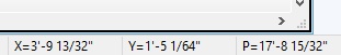
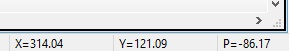
Units. Defines the way of displaying linear coordinates in the information fields of the application, as, for example, X and Y coordinates in the status bar. The parameter does not affect the display of dimensions and other graphic elements.
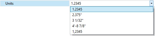
Accuracy. Defines the accuracy of displaying linear coordinates in the information fields of the application, as, for example, X and Y coordinates in the status bar. The parameter does not affect the display of dimensions and other graphic elements.
Angular:
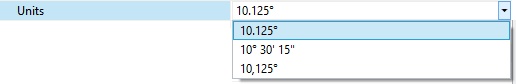
Units. Serves the same purpose as "Linear Units", except for angular coordinates.
![]()
Accuracy. Serves the same purpose as "Linear Accuracy", except for angular coordinates.
Construction Lines:
Search. Defines the mode of selecting straight construction lines. One of two modes can be selected, as follows:
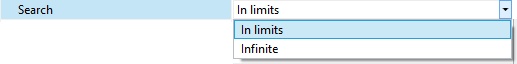
In limits. The lines will be selected according to their length defined by the “Length” parameter on this tab. If construction lines are displayed as finite line segments, then the nearest segment will be selected.
Infinite. The lines will be selected as infinite lines, regardless of the “Length” parameter value on this tab and the way of displaying the lines.
Length. Defines the way of displaying the straight construction lines. Construction lines are displayed as either infinite lines, or finite segments bounded by their end nodes. To refresh the lines display per the new settings, use the command “EC: Edit Construction” under the icon ![]() (use the option “Update all Line extents” under the icon
(use the option “Update all Line extents” under the icon ![]() in the automenu). One can set one of the following construction line display modes:
in the automenu). One can set one of the following construction line display modes:
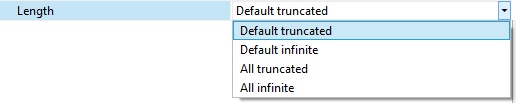
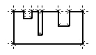
Default truncated. Affects the construction lines whose “Length” property is “Set as default”. Such lines will be displayed as segments bounded by two end nodes.
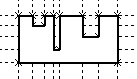
Default infinite. Affects the construction lines whose “Length” property is “Set as default”. Such lines will be displayed as infinite lines.
All truncated. With this value, all construction lines will be displayed as segments bounded by two end nodes.
All infinite. With this value, all construction lines will be displayed as infinite lines.
Extents. Defines extension of construction line overhangs beyond the end nodes when displaying as a finite segment.
Text:
“Transparent” text editing allows to edit paragraph text right after clicking the element with left mouse button. If the attribute is not set, then only the variables inserted in the paragraph text can be edited in this way.