T-FLEX CAD 3D System Operation Tips |
  
|
T-FLEX CAD 3D System Operation Tips |
|
Getting Help
There are several ways of getting answers to the questions arising during the work process, as follows:
● Help on the current command can be accessed by pressing <F1> key or by selecting the menu command "Help|Current". When no command is active, pressing <F1> or selecting "Help|Contents" invokes the help contents.
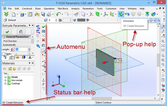
● While within a command, limited information is provided as prompts and hints in the status bar.
● Pop-up help appears by the icon buttons on a toolbar and by the graphic elements when the cursor is briefly held pointing at an element or item. The pop-ups report the command or element name, the type or parent operation of the element. Pop-ups messages are duplicated in the status bar at the bottom of the system window.
●
Creating a New Document. Using Prototype Templates.
A new project begins with setting up the new document. Depending on the design intent one can select appropriate initial options for the new model. To begin with a 2D drawing creation or other 2D construction in 2D window use the command
Icon |
Ribbon |
|---|---|
|
Get started→ Files → Drawing |
Keyboard |
Textual Menu |
<FN>, <Ctrl><N> |
File > New > Drawing |
This will bring up the 2D window.
When beginning directly with a 3D model creation, use the command for creating a new file,
Icon |
Ribbon |
|---|---|
|
Get started→ Files →3D Model |
Keyboard |
Textual Menu |
<F3> |
File > New > 3D Model |
This brings up the 3D window with the standard set of workplanes.
The following commands are used for creation of a new assembly document:
Icon |
Ribbon |
|---|---|
|
Get started→ Files →Assembly Drawing |
Keyboard |
Textual Menu |
|
File > New > Assembly Drawing |
Icon |
Ribbon |
|---|---|
|
Get started→ Files →3D Assembly |
Keyboard |
Textual Menu |
<> |
File > New > 3D Assembly |
An additional record about assembly drawing exists in the product structure of the assembly document.
A new document is created using one of the prototype files whose names are defined via the command "Customize|Options…". These files may contain some useful elements and settings that will be created or set in the new document. In the case the new document settings need to be changed, edit the prototype file (such as, for instance, the ANSI drawing prototype file, named ANSI.GRB, or a 3D model prototype ANSI 3D Front Right Bottom Workplanes.GRB). These prototype files must be present in the folder …T-FLEX CAD\Program\Template.
It is possible to create any number of prototype files and use them as desired. For creating a new file from a prototype, use the dialog “New From…” invoked by the command “FP: Create New Document Based on Prototype” (“File|New from prototype…”). In addition to that, this dialog is available in the window “Start Page”.
Each folder in the directory …T-FLEX CAD\Program\Template becomes a tab in the dialog box. All the prototype files that exist in a respective folder are displayed on the selected tab. Thus, the prototype files should be placed in the directory …T-FLEX CAD\Program\Template\<The respective folder of the prototype file>.
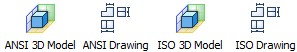
When you create a new document, you can choose one of four prototypes.
To save a file as a prototype use the menu command "File|Save as Prototype". Use the appearing on screen dialog box to assign a name to the would-be prototype file. One can create new folders (turning into tabs on the dialog box) for prototype files as desired. One can also delete any prototype files and folders, except the folder "Common".
Mouse interface. Context menu
Part modeling in T-FLEX CAD 3D is performed mostly by mouse. The keyboard is only used for inputting numerical values, names and command accelerators (see below).
Using left mouse button
● Pointing cursor at an icon and pressing ![]() launches the command represented by the icon.
launches the command represented by the icon.
● A command can also be launched by pointing cursor at a textual menu item and pressing ![]() .
.
● Pointing cursor at an object on the 3D scene and pressing ![]() selects the object.
selects the object.
● Pointing cursor at a 3D construction element or operation and double clicking ![]()
![]() invokes the dialog box "Element/Operation Parameters".
invokes the dialog box "Element/Operation Parameters".
● Pressing and drugging ![]() spins the 3D scene. The cursor must be within 3D window bounds. The system should not be in drawing mode.
spins the 3D scene. The cursor must be within 3D window bounds. The system should not be in drawing mode.
● Drag&Drop can be used for managing libraries and customizing toolbars and dialog boxes. Point the cursor at an element, press and hold ![]() , and drag the element to a desired location while holding the button. For more information, refer to the appropriate sections of documentation.
, and drag the element to a desired location while holding the button. For more information, refer to the appropriate sections of documentation.
Using right mouse button
● While within a command, pressing ![]() cancels the last active command.
cancels the last active command.
● Pressing ![]() while selecting elements on the 3D scene unselects the last selected element.
while selecting elements on the 3D scene unselects the last selected element.
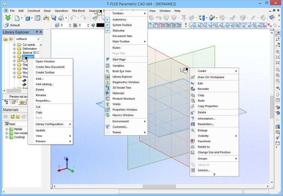
● If no command is active, pressing right button invokes the context menu. The menu is composed of the commands currently available for the particular element. The content of the context menu will be different depending on where the cursor is pointing. These could be the area of the 3D scene, a model element, the command area of T-FLEX CAD, such as a dialog box, a menu, or a toolbar. To launch a command point the cursor at the corresponding line of the context menu and press ![]() .
.
●Context menu can also be invoked while working with dialog boxes. See the topic "Context menu for the dialog fields", the chapter "ST: Set Document Parameters".
The described right mouse button functions are set by default, but can be customized. To do so, call the command "Customize|Options" ("Preferences" tab). For more information, refer to the chapter "Customizing System ".
In "3D drawing" mode mouse manipulations are the same as in 2D window.
Using mouse with wheel (IntelliMouse)
●Spinning the mouse wheel zooms in and out.
●Dragging the mouse with the wheel depressed pans the 3D scene.
●The mouse wheel can also be used for alternative selection from a set of objects under the cursor. Alternative selection mode activates after two-second delay after pointing cursor at the object. Scrolling through the list of objects is done by spinning the wheel.
●Spinning the wheel performs the standard functions of scrolling in the appropriate field of dialog boxes.
Calling commands from keyboard, using an icon, from textual menu
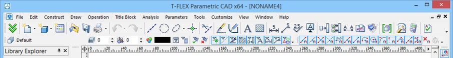
There are various ways of calling T-FLEX CAD commands. Firstly, a command can be selected via an icon on a toolbar using the mouse.
A command can also be launched from the textual menu. All T-FLEX CAD commands are grouped in a certain way. Each group has an entry item in the menu.
Thus, for instance, the commands that create 3D operations are grouped under the entry "Operation". The drawing commands are combined under the entry "Draw". The 2D and 3D construction commands are united in the "Construct" group. The file managing commands are united in the menu "File". Other groups include the editing commands ("Edit"), the variable managing commands ("Parameters"), utility commands ("Tools"), the system and the model customization commands ("Customize"), the visualization controls ("View"), the window management ("Window"). The system reference and information group of commands is under the "Help" entry.
Most T-FLEX CAD commands are bound to function key combinations (simultaneously pressed), or keyboard accelerator sequences (pressed in order). The textual menu item buttons contain keyboard accelerator sequences for the commands next to the command name, whenever defined. The keyboard accelerator can be changed for any command. For detailed description, refer to the "System customization" topic of the chapter "Customizing toolbars and keyboard", "Keyboard" tab.
As said before, some commands can be launched by typing the keyboard accelerator sequence. Particularly, this is supported for 3D model and drawing creation and editing commands. The keyboard sequence and the command name is shown on the pop-up help and in the message field of the status bar.
Just like the 2D subsystem of the T-FLEX CAD, each 3D command has an additional set of options and subcommands accessible via the automenu – a toolbar containing subcommand icons, and function key combinations. The function key combinations are displayed in the pop-up help widgets.
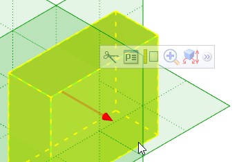
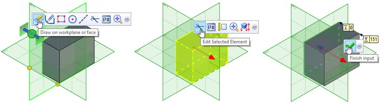
Certain commands are best accessed via the context menu. This menu is available after selecting one or several elements on the 3D scene, such as faces (see diagram below). The context menu contains the list of commands available with the selected set.
You can use dynamic toolbar to call the commands. The toolbar appears upon pressing ![]() .
.
The toolbar provides quick access to frequently used commands and options.
|
If you move cursor from the toolbar, it becomes semitransparent. If you move it too far from the toolbar, the toolbar disappears. When you press |
The ![]() button of operation creation toolbar includes automenu for the current operation. When you select the automenu options, they are not added to the toolbar, because all operations have different automenu options set.
button of operation creation toolbar includes automenu for the current operation. When you select the automenu options, they are not added to the toolbar, because all operations have different automenu options set.
You can change dynamic toolbar display settings on the Dynamic toolbar tab of SO: Set system options command.
Confirming actions of 3D element creation
Unlike 2D elements, a three-dimensional element creation takes several steps. Not all of these steps are required. To complete an element definition, use the provided option "Finish input" by clicking on the icon ![]() or pressing <Y> key. This option becomes accessible only after the required minimum sequence of actions has been completed.
or pressing <Y> key. This option becomes accessible only after the required minimum sequence of actions has been completed.
When calling a command, make sure about the command exiting option. Some commands remember the current state while the others revert to the initial settings.
Canceling and exiting a command
Exiting a command is done by pressing <Esc> key or ![]() . Alternatively, use the
. Alternatively, use the ![]() automenu icon.
automenu icon.
If the system has entered a 3D command without doing anything (nothing was selected), then calling another 3D command makes the former command quit. However, if something has been selected within the former command then the newly launched command does not close the former one and becomes nested. Once done with the nested command, the system returns into the former command. This is different in 3D mode from the 2D mode operation. The above does not affect the 3D drawing mode. To return to the command-waiting mode, close subsequently all active commands. Instant exiting from all nested commands is done by simultaneously pressing <Shift><Esc>. A 3D command quits automatically upon calling any 2D command.