Creating Standard Workplane |
  
|
Creating Standard Workplane |
|
Creating standard workplane in the 3D window
In the cases when the new document was not based on the standard prototype, you may need to manually create one or several standard planes. To do this, activate the 3D window, and in the workplane creation command select the option:
![]() <S> Construct standard Workplane
<S> Construct standard Workplane
A standard workplane can be created either in the 2D or in the 3D window. The way of creating the plane and the obtained result depend on what window was active at the time of selecting this option.
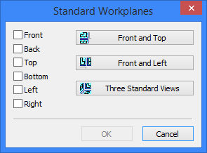
The dialog box appears in the screen for selecting standard views. The workplanes will be made parallel to the respective principal coordinate planes, as defined by the selected views. One can select several standard views simultaneously in the list on the left-hand side. Confirming the selection by pressing the [OK] button leads to automatic creation of the workplanes for the specified views. Separate "Workplane"-type 2D pages will be created for each workplane. Such pages are not displayed in the 2D window by default.
The displaying of the workplane pages in the 2D window can be turned on using the command "Customize|Pages", by setting the flag "Show Pages/Workplanes". Such workplanes are displayed in the 3D view by default. The position in the three-dimensional space is determined by the world coordinates that provide the common origin for all workplanes created in this way.
The origin of each workplane is located in the center of the rectangle that defines the workplane display in the 3D window. A standard workplane origin can be modified only in the editing mode. In this case, the origin selection is done in the same way as when creating workplanes based on a 2D view (the section "Creation of standard workplane in 2D window").
Simultaneous creation of several standard workplanes
The dialog box launched by the option ![]() has another three additional options represented by the graphic buttons: [
has another three additional options represented by the graphic buttons: [![]() Front and Top], [
Front and Top], [![]() Front and Left], [
Front and Left], [![]() Three Standard Views]. You can simultaneously create several standard workplanes by using these options.
Three Standard Views]. You can simultaneously create several standard workplanes by using these options.
Creating standard workplane in 2D window
Creation of workplanes in the 2D window, that is, based on an already existing page of a 2D drawing, containing 2D constructions, is mostly used with the technique "From 2D to 3D". Usually, standard planes are created for each of the main drawing views. The 3D constructions on the planes are built based on the drawings on the respective drawing views. This allows carrying the elements of a complete 2D drawing over the three-dimensional space.
To create a standard workplane in the 2D window, use the option ![]() . The sequence of steps for creating the plane in this case is as follows:
. The sequence of steps for creating the plane in this case is as follows:
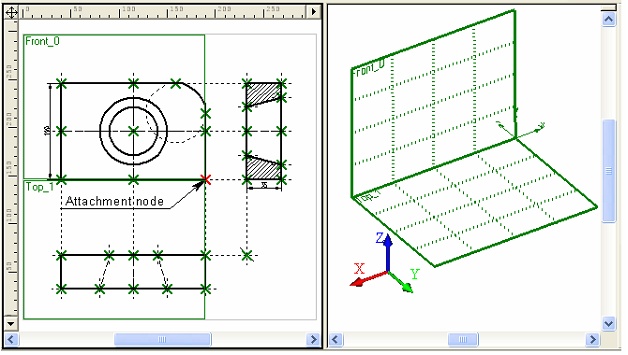
1. Determine, to which of the principal coordinate planes the workplane being created should be made parallel. This is done by selecting the view for the workplane. For example, by selecting the front or back view, we assume that the plane being created is positioned parallel to the XZ plane of the world coordinate system.
2. Select a 2D node on the current page of the drawing (optional in some cases). The node will define the position of the workplane borders rectangle on the page, as well as the origin of the plane local coordinates. If no workplane is yet linked to this drawing page, then you do not need to specify the node. In this case, one of the corners of the drawing format frame will be assumed as the local coordinate system origin.
The default workplane borders are set as follows. The specified 2D node is considered the first corner of the border rectangle. The second corner is placed at the nearest corner of the drawing format frame. Standard planes are assigned a specific corner of the format frame, the front view being the upper left one, the bottom view – the lower left, the left view – the upper right.
The correct definition of the displayed borders of the workplane helps simplify the future creation of 3D constructions on the plane from the 2D drawing. When selecting 2D elements to use for 3D constructions, you need to define, in which workplane those elements belong. The system can do it automatically by taking the plane, whose border rectangle covers the selected 2D elements. If the borders of the planes on the 2D page do not align with the respective drawing views, the system choice will be incorrect, and you will have to select the workplane manually. Therefore, the attachment node should be selected in such a way, that the workplane border rectangle agreed with the drawing view intended for the plane. If this cannot be achieved by selecting the attachment node, the border size and position of the workplane being created can be additionally adjusted, as described in the next paragraph.
3. Change the default settings of the plane displayed borders in the 2D window (optional). The borders can be modified in two ways. The first way is selecting another corner of the drawing format frame as the second point of the border. The second way is to define the borders of the plane anew by specifying the new positions for both corners (by selecting two 2D nodes).
4. Select a 3D node defining the position of the workplane in the space (optional). By default, the standard workplane coincides with one of the principal coordinate planes of the world coordinate system. The origin of its local coordinate system is positioned in this case at the world coordinates origin. Instead, if defining the 3D node, the plane being created is carried over to the position defined by the selected node. That means, the resulting plane will be parallel to the principal coordinate plane while passing through the 3D node. The plane local coordinates origin is also placed at the selected 3D node.
5. Define the displayed borders of the plane in the 2D window (optional). The default borders of a workplane are defined as follows. The first point is considered the point selected at the step 2. The second point is considered the nearest corner of the drawing borders. In the case of standard planes, a certain corner point is used (for the front view – the upper left one, for the bottom view – the lower left, for the left view – the upper right). The user can modify these borders (by selecting, for instance, two 2D nodes).
6. Upon performing the necessary steps, confirm the workplane creation by the option:
![]() <Y> Finish input
<Y> Finish input
The workplane created in this way is not displayed by default in the 3D window. To have it displayed in the 3D scene, set the flag "Show in 3D View" in its parameters dialog box.
Let's review each step in details.
Activate the 2D window and select the option "Construct standard Workplane". The dialog for selecting the standard view will be displayed on the screen. Unlike its counterpart for creating the standard plane in the 3D window, this dialog allows selecting only one standard view from the list on the left-hand side. If no workplanes exist on the current drawing page, then the rectangle will be drawn the size of the drawing format, marking the workplane being created.
Workplane creation can be completed at the step, using the option ![]() . The workplane local coordinate system origin will be set automatically.
. The workplane local coordinate system origin will be set automatically.
If, however, there is at least one workplane on the current drawing page, then the workplane image will be displayed on the drawing only after performing the further steps. The following additional options are provided in the command automenu:
![]() <N> Set Attachment point
<N> Set Attachment point
![]() <M> Set relation with 3D Node
<M> Set relation with 3D Node
![]() <B> Define Workplane borders
<B> Define Workplane borders
Suppose that the "Left" view was selected at the previous step. This means, the workplane being created will coincide (or stay parallel) with the YZ plane of the world coordinate system. After that, you can select a 2D node that will define the local coordinate system origin on this workplane. The node is selected using the option ![]() . The workplane creation can be finished at this step. In this case, it will coincide with the YZ plane of the world coordinates.
. The workplane creation can be finished at this step. In this case, it will coincide with the YZ plane of the world coordinates.
If necessary, the workplane borders set by default can be modified (the option ![]() ). When calling this option, the following additional options become available in the automenu:
). When calling this option, the following additional options become available in the automenu:
![]() <B> Set border's 1st/2nd corner
<B> Set border's 1st/2nd corner
![]() <Tab> Define Workplane borders
<Tab> Define Workplane borders
![]() <K> Eliminate borders
<K> Eliminate borders
![]() <W> Return to previous mode
<W> Return to previous mode
The borders of the workplane can be redefined in two ways. You can simply select another corner of the drawing format frame as the second point, using the option ![]() : pressing the icon repeatedly makes the system toggle through all corners of the format frame. Alternatively, you can define the plane borders anew, attaching them to two nodes by the option
: pressing the icon repeatedly makes the system toggle through all corners of the format frame. Alternatively, you can define the plane borders anew, attaching them to two nodes by the option ![]() . Attachments to the nodes can be canceled by the option
. Attachments to the nodes can be canceled by the option ![]() .
.
The final step can be exact positioning of the plane being created in the space by specifying a 3D node (the option ![]() ).
).
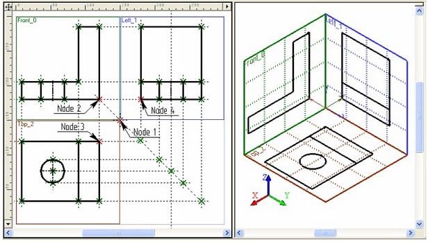
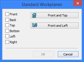
As in the case of creating a standard plane in the 3D window, multiple planes can be simultaneously created in the 2D window. However, in this case only two additional buttons are present in the dialog lunched by the option ![]() : [
: [![]() Front and Top] and [
Front and Top] and [![]() Front and Left]. Using these options, you can create two standard workplanes at once. In this case, simply specify the common coordinate system origin as a 2D node.
Front and Left]. Using these options, you can create two standard workplanes at once. In this case, simply specify the common coordinate system origin as a 2D node.