Pages |
  
|
Pages |
|
For working convenience, T-FLEX CAD system provides a capability of creating multi-page documents. For example, it is handy to have in one file, yet on separate pages, auxiliary 2D constructions used in the main 3D model, as well as projections and sections of the 3D model with dimensions, or the BOM, etc. The elements can meanwhile interact with each other via the created relations, variables, databases, etc.
General information
A T-FLEX CAD document can have an arbitrary number of pages. Each created document has at least one page.
Pages in T-FLEX CAD are divided into six types, depending on their purpose and the way of creation: "Normal", "Auxiliary", "Controls", "Workplane", “Text”, “Bill of Materials”. Such division is not strict: the type of a page in most cases can be changed by the user. Types help controlling page display. Depending on the drawing settings, the 2D window will display all pages in the document, or only the pages of certain types. Therefore, the user can manage page visibility while working with multi-page documents, hiding from display those unused at the moment.
Each page uses its own drawing settings defined in the command "ST: Set Document Parameters", such as the paper format, drawing scale, font parameters, detailing elements, colors, properties of element display, etc. The settings made in the command Customize > Levels… also affect only the page that was current when the settings were made. When calling File > Export command, the system processes the current page of the drawing (except exporting to the AutoCad format, when all pages of the documents are getting converted).
Modifications of "default" parameters affect all pages (see "Default parameters" section of the "Set Document Parameters" chapter). The same is true for managing layers in the command "QL: Configure Layers".
If a T-FLEX CAD document contains several pages, the tabs with names of visible pages are displayed in the bottom of the drawing window. Visibility of the tabs can be controlled with the help of the flag Customize > Tool Windows > Page Tabs found in the textual menu. Switching pages is done without leaving the current command. This help creating, say, a copy or a detail view by selecting elements located on different pages.
Managing document pages
Working with Page Tabs. Tabs Control
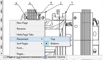
Page tabs, by default, are located along the lower border of the T-FLEX CAD document window. If necessary, their location can be changed by moving the page tabs upwards, as it was done in the previous versions of the T-FLEX CAD. To do it, it is enough to point with the cursor at the page tab, call the context menu with the help of ![]() and change the value of the toggle “Tabs placement” to the required one (“Top” or “Bottom”).
and change the value of the toggle “Tabs placement” to the required one (“Top” or “Bottom”).
Page tabs are used for quick shifting between pages of the current document. For shifting to the required page of the document, it is enough to point with the cursor at its tab and press ![]() . Moreover, for shifting between pages the keys <Page Up>, <Page Down> can be used as well.
. Moreover, for shifting between pages the keys <Page Up>, <Page Down> can be used as well.
If the <Page Down> is pressed while being on the last page of the current document, the system will offer to create a new page. The created page will be placed at the end of the list of pages of the given document. It is also possible to create a new page by using the command “New Page” found in the context menu for the tab of any page.
On each page tab, the page name as well as the symbol showing its type are displayed. By default, the system gives to the pages the names “Page 1”, “Page 2”, etc. , however, afterwards these names can be changed to more meaningful ones to make the work more convenient. To rename the page, the command “Rename” can be called from the context menu of the page tab. After calling this command, the system will shift to the mode of editing the text shown on the tab.
![]()
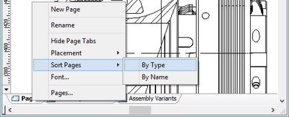
The order in which the pages of a document are arranged can be changed. It is possible to quickly sort the pages by names or by types with the help of the commands “Sort Pages|Name” and “Sort Pages|Type” found in the same context menu called for any tab of the current document.
An arbitrary change in the page arrangement can be carried out just by dragging the page tab to another place. To do it, bring the cursor to the required tab, press ![]() and without releasing the mouse button, drag the cursor to the required position in the list of tabs.
and without releasing the mouse button, drag the cursor to the required position in the list of tabs.
Let's talk more about the context menu for the page tabs. With the help of the command “Font…” it is possible to modify font parameters used for displaying the text on the page tabs. Upon calling this command the standard window of font parameters opens up.
The command “Delete” allows removing the page on the tab of which the context menu has been called. If the page being removed contains some drawings, the system will inform about that and ask a user to confirm the necessity of page removal and all its contents.
The command “Pages…” invokes the dialog for controlling pages of the document. This dialog allows performing all possible operations with pages: create and delete pages, rename, change the type of page and its location in the list of pages. We will tell more about working with this dialog in the section “Working with Dialog «Pages»” below.
The last command of the context menu – “Hide Page Tabs” – turns off the display of the page tabs for the document. After the tabs were turned off, it is possible to turn the display of the page tabs back on with the help of the flag “Customize|Tool Windows|Page Tabs”.
Creating new pages
Additional pages can be created in a T-FLEX CAD document by the following means:
1. Using the <Page Down> key. When created, such pages are automatically assigned the type "Normal".
2. Via the help of the command “New Page” in the context menu of the page tabs;
3. Via the command "PG: Pages" (see the section “Working with Dialog «Pages»”);
4. Automatically while working in certain commands. The type of a thus created page depends on the actual command. For example, the "TR: Create Control" command allows creating a page of the type "Controls", while the command "SD: Create Drawing View"– a page of "Auxiliary" type. The command "3W: Construct Workplane" creates pages of the type "Workplane", while "Normal" type pages are created under "BC: Create Bill of Materials" and "BM: Bills of Materials".
The quickest way of creating a new page is use of the <Page Down> key.
To create a new page, go to the last page of the drawing and press the <Page Down> key. After that, confirm the new page creation query. The new page is created as a result. It is automatically assigned a new name "Page N", where N is the page number. At creation, the page settings are copied from the last active page.

These settings can later be modified by activating the page and calling the command "ST: Set Document Parameters".
Creation of pages as per the item 3 is described in the respective chapters of the mentioned commands.
Working with Dialog «Pages»
The dialog “Pages” allows performing practically all possible operations with the pages of the current document. Several options are available to call this dialog. First of all, it can be called with the help of the command:
Icon |
Ribbon |
|---|---|
|
Edit → Document → Pages |
Keyboard |
Textual Menu |
<PG> |
Customize > Pages |
Moreover, the dialog “Pages” can be called via the toolbar “View” and from the context menu for the document tabs.
The main pane of the dialog contains the list of pages displayed in the 2D drawing window: names and types of pages.
In the bottom portion of the dialog box is the "Show Pages" group of flags for managing the list contents (and, therefore, the 2D window display) regarding the pages of a certain type, as follows:
Workplanes.
Controls.
Auxiliary.
Text.
Bill of Materials.
Pages of the type "Normal" are always present in the list and in display in the 2D document window.
Having selected a page in the list by clicking ![]() , you can change its type by choosing the required value from the drop down list “Page Type”. Pages of the type "Workplane" are created only with a workplane creation by the appropriate commands. Their type can't be changed.
, you can change its type by choosing the required value from the drop down list “Page Type”. Pages of the type "Workplane" are created only with a workplane creation by the appropriate commands. Their type can't be changed.

The graphic buttons at the right-hand side of the dialog box allow the following actions over the selected page in the list:
[New]. Creates a new page of the drawing. Upon pressing the button, a new page is added in the document, launching the name editing mode. The page type is "Normal" by default. If necessary, you can assign the desired type via the parameter "Page Type".
[Copy] Creates copy of the selected page with its parameters.
[Delete]. Deletes the drawing page selected in the list. If the page is not empty (i.e. contains some elements), the system queries the user whether to delete objects on the page or associated with the page. Positive answer results in deleting the page and all associated objects, the negative one cancels deletion.
[Rename]. Changes the name of the page. The page name is displayed on the tab. Clicking on the name of the selected page entry in the list highlights the name and allows its editing. When pages of the type "Workplane" are renamed, the "Name" parameter of the workplane changes according to the new name of the page.
[Up]. Moves the selected page entry in the list one line up.
[Down]. Moves the selected page entry in the list one line down.
Note that the order of pages in the document, as reflected by the tabs, corresponds with their positions in the list being described.
[Select]. Activates the selected page. Opens the selected page in the 2D drawing window.
[Close]. Closes the "Pages" dialog box. Completes the command.
Modifying page parameters
Each page has its own settings defined via the command "ST: Set Document Parameters". The page size can also be modified directly in the 2D window by the command "PZ: Set Paper Size":
Icon |
Ribbon |
|---|---|
|
Workplane → Modes → Page size |
Keyboard |
Textual Menu |
<PZ > |
Customize > Page Size |
The command is used for modifying the size of a page and its position. Modifying the page size parameters affects the "Paper size" parameters on the "Paper" tab of the command "ST: Set Document Parameters".
Upon calling the command, the borders of the current page highlight, outlined by a box with graphic controls of a square shape along the perimeter for resizing. If pointed to one of these squares, the mouse cursor changes to ![]() . It can be dragged now with the left mouse button depressed, modifying the size of the box diagonal. If pointed to a box mid-side square, the mouse cursor changes to
. It can be dragged now with the left mouse button depressed, modifying the size of the box diagonal. If pointed to a box mid-side square, the mouse cursor changes to ![]() and can be dragged now with the left mouse button depressed, modifying the vertical or horizontal size of the box, respectively. If within the box, the mouse cursor changes to
and can be dragged now with the left mouse button depressed, modifying the vertical or horizontal size of the box, respectively. If within the box, the mouse cursor changes to ![]() and can be dragged now with the left mouse button depressed, modifying the box position.
and can be dragged now with the left mouse button depressed, modifying the box position.
The following options are available in the automenu in this mode:
![]() <End> Finish input
<End> Finish input
![]() <P> Set page size
<P> Set page size
![]() <Esc> Exit command
<Esc> Exit command
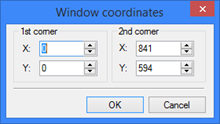
The option ![]() allows entering numerical values of the page corners in global coordinates. Upon modifying the size and/or position of the page, confirm the input with the option
allows entering numerical values of the page corners in global coordinates. Upon modifying the size and/or position of the page, confirm the input with the option ![]() . The grid can be brought up on the active page, and grid snapping turned on, by using the command "QG: Change Grid settings".
. The grid can be brought up on the active page, and grid snapping turned on, by using the command "QG: Change Grid settings".
Special handling of multi-page documents
As mentioned above, each page of a multi-page document in T-FLEX CAD can be used for creating various elements: nodes, construction and graphic entities, hatches, text, etc. if necessary, elements can be moved/copied from one page to another.
Elements located on different pages of the same document can be totally independent of each other, or, vise versa, related by various means: by the copy operation, by projective relations, via variables and databases. Besides, T-FLEX CAD allows creating elements located on several pages simultaneously. When creating text or BOM elements, one can define transition to the new page if the element being created is getting out of current bounds. As a result, each page will display the respective part of the multi-page element. Editing and parameter modification commands work on the whole element, regardless of the portion selected in the command.
A multi-page document, just as any other T-FLEX CAD document, can be inserted into another document as a fragment or picture, exported in other graphic formats or printed. Each of these situations will be reviewed separately.
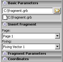
● When using a multi-page document as a fragment in an assembly, only one page of the fragment document is inserted. Therefore, when inserting, the user can specify the particular page of the fragment drawing to assemble, along with specifying fixing points or vector and defining the fragment variables.
● When inserting a multi-page document in another drawing as a picture only one page of the selected document is inserted as well. The required page is determined by the user upon inserting a picture.
● When exporting a multi-page document into another graphic format, the output graphic file will contain the document page that was active when the export command was called (except exporting to the AutoCAD format).
● When printing a document, the user can specify the pages to print in the print parameters dialog box.