Brief Introductory Course. 2D Drawing |
  
|
Brief Introductory Course. 2D Drawing |
|
This chapter introduces various drawing techniques. The manual describes all necessary steps in the drawing process. Once you start drawing with T-FLEX CAD, you will have an opportunity to fully appreciate the advantages of this system. Further you will learn the basic commands and principles of creating a drawing with the aid of T-FLEX CAD.
T-FLEX CAD supports creation of two types of drawings: parametric and nonparametric (sketches). The mainly used type is the parametric drawing.
It takes somewhat more time resources to create a parametric drawing; nevertheless, later on such drawing will be easily modifiable as you desire. A nonparametric drawing (sketch) can be created faster. Its creation method is similar to the ways of drawing in some other CAD systems. However, nonparametric drawings do not possess the advantage of effective parameter (dimension) modification. Therefore, this method is recommended to use in the cases when no significant modifications to a drawing are expected.
To speed up creation of parametric drawings, the system supports the use of automatic parameterization. This mode allows constructing not too complicated parametric drawings just like nonparametric ones: all you do is create graphic lines using object snapping. The construction lines constrained by the parametric relation will be automatically "slipped under" the graphic lines by the system.
Three approaches to creating a T-FLEX CAD drawing will be reviewed below: creating a parametric drawing by the traditional method (that is, with the manual creation of construction elements), creating a nonparametric sketch drawing, and creating a parametric drawing in the automatic parameterization mode.
Creating parametric drawing
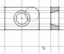
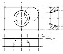
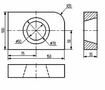
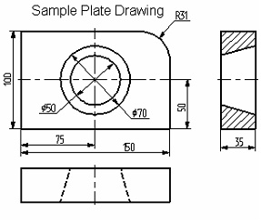
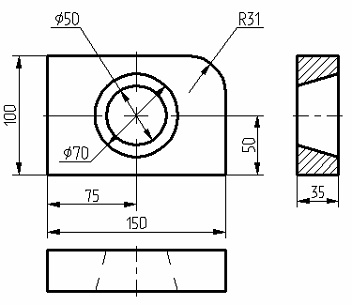
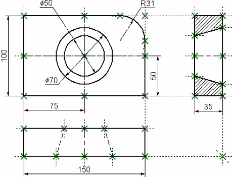
The following diagram shows a drawing to be created. It is a plate with a through hole of conical shape. The drawing will be defined parametrically so that any modifications will automatically reflect on all projections. Let's begin with the main (elevation) view of the plate. First, create the necessary "thin" construction lines, and then draw the graphic lines on top. Next, create the other two views using the construction lines of the main view. This creates a dependency between the views so that the two views automatically adjust to the main view modifications. Finally, apply text and dimensions. As was mentioned, any command can be called by a number of ways. It can be typed on the keyboard, selected from the textual menu, or picked on a toolbar.
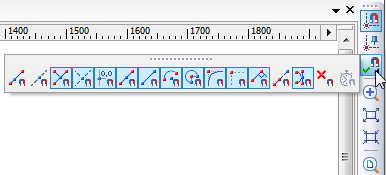
Let's begin with the command "L: Construct Line". To invoke the command, use
Icon |
Ribbon |
|---|---|
|
Draw → Construct → Line |
Keyboard |
Textual Menu |
<L> |
Construct > Line |
Pick the icon |
|
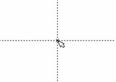
As a result, two crossing construction lines will be created. Besides, a node is created at the intersection point. These lines make the basis of the view being created. The line parameters represent the absolute coordinates. The view can be moved around on the drawing by moving the base lines.
Do not use more than two base lines on the main (independent) view, and more than one base line on the views defined by projections. This will insure freedom in placing the drawings.
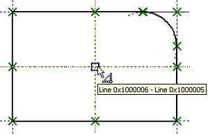
A T-FLEX CAD command stays active up until it is quit or another command is called. Quitting the crosshair mode (as by pressing ![]() once) cancels the crosshair rubberbanding, but the line creation command stays active. After canceling the crosshair mode, move the cursor close to the vertical line. The line will get highlighted, and a pop-up help will appear next to cursor displaying the name of the highlighted entity. This is object snapping in action. This behavior relieves the user from typing on keyboard or using the automenu buttons.
once) cancels the crosshair rubberbanding, but the line creation command stays active. After canceling the crosshair mode, move the cursor close to the vertical line. The line will get highlighted, and a pop-up help will appear next to cursor displaying the name of the highlighted entity. This is object snapping in action. This behavior relieves the user from typing on keyboard or using the automenu buttons.
The object snapping is on by default when starting the application. To set or unset this mode manually, use the button ![]() on the "View" toolbar.
on the "View" toolbar.
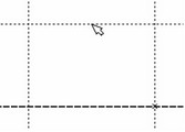
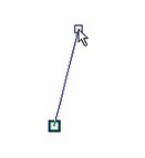
Pressing ![]() now starts rubberbanding of a line that follows the cursor while staying parallel to the selected one. We are now creating a line parallel to a vertical line. Such a relationship between the two construction lines, established at the creation time, is an example of an important feature of T-FLEX CAD system. This defines behavior of a set of construction entities under parametric modifications.
now starts rubberbanding of a line that follows the cursor while staying parallel to the selected one. We are now creating a line parallel to a vertical line. Such a relationship between the two construction lines, established at the creation time, is an example of an important feature of T-FLEX CAD system. This defines behavior of a set of construction entities under parametric modifications.
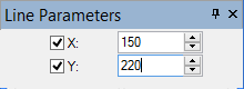
Place the new line at the left of the highlighted vertical line by pressing ![]() . The exact value of the distance can be specified in the property window or parameter dialog box. The newly created line will become the left side of the part.
. The exact value of the distance can be specified in the property window or parameter dialog box. The newly created line will become the left side of the part.
Pressing |
|
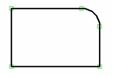
The next step is to round a corner of the plate with a fillet. For this purpose, let's use the command "C: Construct Circle". Call the command via
Icon |
Ribbon |
|---|---|
|
Draw → Construct → Circle |
Keyboard |
Textual Menu |
<C> |
Construct > Circle |
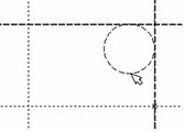
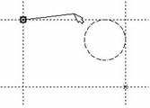
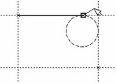
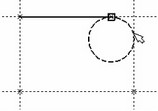
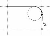
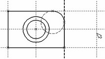
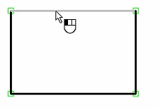
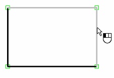
To draw the fillet at the top-right corner of the plate, construct a circle tangent to the top and the right lines. Move the cursor to the top line and press |
|
Next, move the cursor to the right line and again press |
|
If the resulting construction does not match the illustration, use "UN: Undo Changes" command,
Icon |
Ribbon |
|---|---|
|
|
Keyboard |
Textual Menu |
<UN>, <Ctrl><Z>, <Alt><BackSpace> |
Edit > Undo |
Each call to this command brings the system one step back. If this command was called mistakenly, its action can be reversed with the command "RED: Redo Changes"
Icon |
Ribbon |
|---|---|
|
|
Keyboard |
Textual Menu |
<RED>, <Ctrl><BackSpace> |
Edit > Redo |
This restores the action that was mistakenly undone.
One can remove all construction lines and start creating a drawing from the beginning with the command "PU: Delete Unused Construction":
Icon |
Ribbon |
|---|---|
|
Edit → Additional → Purge |
Keyboard |
Textual Menu |
<PU> |
Edit > Purge |
This will delete all construction entities and allow to start drawing anew. A specific construction entity can be deleted using command "EC: Edit Construction":
Icon |
Ribbon |
|---|---|
|
Draw → Additional → 2D Construction |
Keyboard |
Textual Menu |
<EC> |
Edit > 2D Construction |
Once the command is called, select the entity and delete it by pressing <Delete> key on the keyboard or by picking the icon ![]() in the automenu.
in the automenu.
Now, draw the graphic lines on top of the completed construction portion of the drawing. To do so, let's create graphic lines by calling "G: Create Graphic Line". Call the command via
Icon |
Ribbon |
|---|---|
|
Draw → Draw → Graphic Line |
Keyboard |
Textual Menu |
<G> |
Draw > Graphic Line |
Note that the previous command is automatically terminated when calling another command via the toolbar icon button or the textual menu (no need to cancel the previous one explicitly).
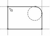
Start drawing solid lines from the top-left corner of the plate. The graphic lines snap automatically to a closest intersection of the construction lines. Simply move cursor to an intersection and press |
|
It is not recommended to select multiple (more than two) line intersections neither by pressing <Enter> nor by ![]() . In this case, we recommend creating nodes at such intersections first. The graphics can then be applied using the <N> key. When using the <Enter> key in "free drawing" mode, a "loose" node will be created that is not constrained to any construction line. Following these tips insures correct parametric function of the drawing under modifications.
. In this case, we recommend creating nodes at such intersections first. The graphics can then be applied using the <N> key. When using the <Enter> key in "free drawing" mode, a "loose" node will be created that is not constrained to any construction line. Following these tips insures correct parametric function of the drawing under modifications.
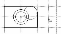
Move cursor to the tangency point between the top line and the circle, and press |
|
Now let's draw a graphic line along the circle to construct an arc between the two tangency points. To do so, move the cursor to the circle and press <C> key. The circle will then get highlighted. The direction of arc creation depends on the position of the cursor when selecting the circle. To change the arc direction, press the <Tab> key. Place the cursor just above and to the left of the second tangency point as shown. |
|
Then press |
|
Continue drawing. Select with |
|
If applying graphic lines did not come out as desired, edit the graphics using the command "EG: Edit Graphic Line". Call as follows,
Keyboard |
Textual Menu |
Icon |
<EG> |
Edit > Draw > Graphics |
|
Move the cursor to one of the lines to be edited, and press ![]() . This selects the line. It can then be deleted by pressing <Delete> key or picking the icon
. This selects the line. It can then be deleted by pressing <Delete> key or picking the icon ![]() in the automenu. Repeat for each line to be edited. If a whole area is to be edited, use box selection. To select by box, press
in the automenu. Repeat for each line to be edited. If a whole area is to be edited, use box selection. To select by box, press ![]() where one of the box corners should be, hold and drag to the desired location of the opposite corner, then release the button. As you drag the cursor, it rubberbands a rectangle of the selection box. The elements will be selected that are fully within the box. All these elements can be deleted at once.
where one of the box corners should be, hold and drag to the desired location of the opposite corner, then release the button. As you drag the cursor, it rubberbands a rectangle of the selection box. The elements will be selected that are fully within the box. All these elements can be deleted at once.
To apply graphic lines again, call the command "G: Create Graphic Line". To redraw the screen at any moment use the <F7> key, in case not all lines are displayed properly after editing.
Once the desired image is created, proceed to the next chapter. The drawing can be saved using command "SA: Save Model":
Icon |
Ribbon |
|---|---|
|
|
Keyboard |
Textual Menu |
<SA> |
File > Save |
Congratulations! You have accomplished your first drawing in T-FLEX CAD. Now let us briefly describe the system editing capabilities.
The current drawing uses five construction entities that define the shape and size of the part. These are the left side, the right side, the top, the bottom and the fillet radius. To modify construction entities call the command "EC: Edit Construction":
Icon |
Ribbon |
|---|---|
|
Draw → Additional → 2D Construction |
Keyboard |
Textual Menu |
<EC> |
Edit > 2D Construction |
Move the cursor to the left vertical line and press ![]() . The line gets highlighted. As you move the cursor left to right, the line will move along. Specify the new position of the line by pressing
. The line gets highlighted. As you move the cursor left to right, the line will move along. Specify the new position of the line by pressing ![]() . The width of the plate will change. Note that modifying locations of construction entities causes instant update of their respective "snapped" graphic lines. If you try to move the right side of the plate then the whole plate will move. This is because the left side was created as a dependent of the right, and the dependency stays as the right side is modified. However, the left side can move independently of the right. Try such manipulations with other construction entities, including the circle. As the construction entities move the size and shape of the plate will be changing while maintaining the dependencies defined at the construction time.
. The width of the plate will change. Note that modifying locations of construction entities causes instant update of their respective "snapped" graphic lines. If you try to move the right side of the plate then the whole plate will move. This is because the left side was created as a dependent of the right, and the dependency stays as the right side is modified. However, the left side can move independently of the right. Try such manipulations with other construction entities, including the circle. As the construction entities move the size and shape of the plate will be changing while maintaining the dependencies defined at the construction time.
After testing modification capabilities of the system please bring the drawing back into an approximately original configuration as shown on a diagram above. Let's proceed with the next element of the drawing, which is the conical hole in the middle of the plate.
First, let's define the center of the circle to be constructed. To do so, let's do auxiliary construction to define the center point of the plate. T-FLEX CAD provides a handy command to create a line in the middle of two others. For two parallel lines, this command creates a parallel line in between at equal distances to the two. For intersecting ones, the resulting line passes through the intersection at equal angles to the two original lines. Thus, the new line appears as the symmetry line for the two. Call the command "L: Construct Line" and select two lines one by one, using <L>, and again, <L> key.
Call the command ![]() “L: Construct Line” and choose the icon
“L: Construct Line” and choose the icon ![]() in the automenu. Move the cursor to the right side of the plate and select the vertical line by
in the automenu. Move the cursor to the right side of the plate and select the vertical line by ![]() . A parallel line appears rubberbanding after the cursor. Move the cursor to the left side of the plate without fixing the rubberbanded line. Now, select the left vertical line with
. A parallel line appears rubberbanding after the cursor. Move the cursor to the left side of the plate without fixing the rubberbanded line. Now, select the left vertical line with ![]() . This creates a new vertical line on the drawing that is the symmetry line for the two selected ones.
. This creates a new vertical line on the drawing that is the symmetry line for the two selected ones.
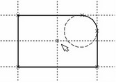
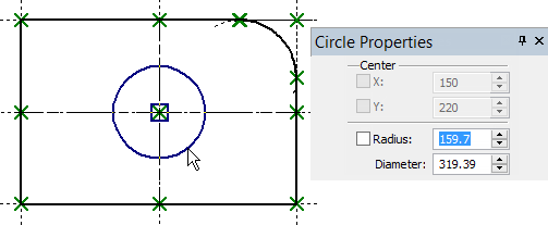
Follow same way to create a horizontal line as the symmetry line for the top and bottom sides of the plate. The intersection point of the two new lines will be the center of the hole to be constructed. Next, call the circle creation command, move cursor to the intersection of the symmetry lines, and press |
|
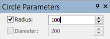
The circle center snaps to the node created automatically at the intersection of the symmetry lines. Fix the circle with ![]() . Just like line-to-line distances, the circle radius (diameter) can be defined approximately by mouse operation, and exactly in the property window. Note that after pressing
. Just like line-to-line distances, the circle radius (diameter) can be defined approximately by mouse operation, and exactly in the property window. Note that after pressing ![]() the command "C: Construct Circle" stays active.
the command "C: Construct Circle" stays active.
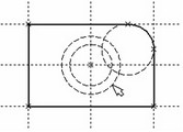
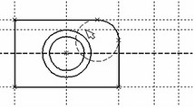
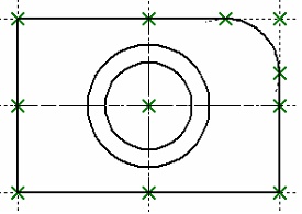
The second circle of the conical hole can be constructed as concentric to the first one. To do so, pick the icon |
|
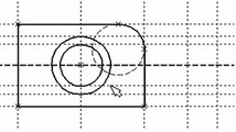
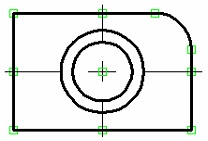
Proceed with the command "G: Create Graphic Line", move cursor to the bigger of the two circles, and press ![]() or <C>. The circle gets drawn in solid. Then, move the cursor to the smaller circle, and again press
or <C>. The circle gets drawn in solid. Then, move the cursor to the smaller circle, and again press ![]() or <C>. Now both circles are drawn solid. From this point, we can proceed with the two other views of the plate.
or <C>. Now both circles are drawn solid. From this point, we can proceed with the two other views of the plate.
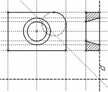
The two other views are not required for constructing a parametric drawing in T-FLEX CAD. In this example, creating the side and the plan views simply help demonstrating additional advantages of parametric modeling using T-FLEX CAD system.
Since the straight lines are considered infinite, one can see that the other views (side and plan) are already partially created. To finalize the drawing, we will need to establish additional dependencies between the construction lines. These additional steps are described next.
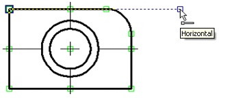
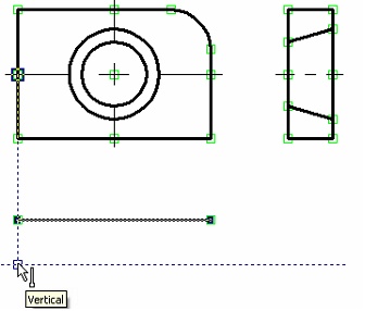
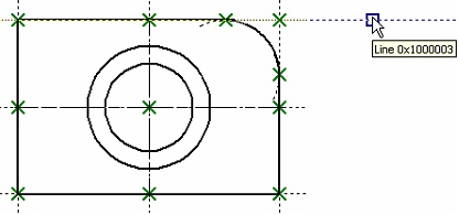
Activate the line creation command and move the cursor to the construction line defining the right side of the plate. Select it with |
|
The new line is created relative to the right side of the plate on the main view. Therefore, when the right side of the plate is moved, the new line will follow, staying at the same distance. To place the new line at a different distance, use the command for editing construction lines. After that, moving the right side of the plate will again preserve the new distance. The dependencies between construction entities stay valid until redefined in the construction line editing command.
The next step is creating the line of the left edge of the part on the side view. After completing one line, a new line rubberbanding began automatically.
Note that the currently rubberbanded second line is also a dependent of the plate right-side line as the latter is still highlighted. This is not our intention; therefore, press |
|
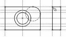
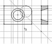
Now let's proceed with constructing the projection of the conical hole. First, let's create horizontal lines tangent to the top and bottom of the inner and outer circles of the hole. These lines will be used as guides for the side view of the hole. Press |
|
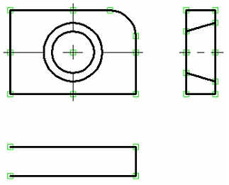
Now we have the necessary guides for applying graphics on the side view. Call "G: Create Graphic Line" command and apply solid lines between the four corners of the plate side view. Simply move the cursor from corner to corner clicking |
|
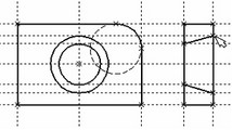
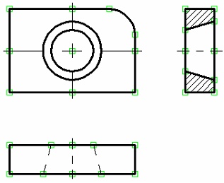
Next, apply the two lines representing the conical hole. The view is now almost complete, with only the hatch yet to be created. The hatch is created by "H: Create Hatch" command. Set the following option, unless on by default,
|
|
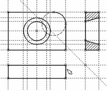
Then move the cursor to the top portion of the side view, place within the area to be hatched, and press |
|
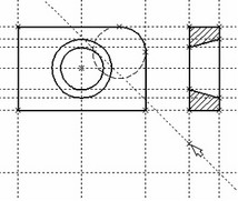
Once the hatch is created, proceed with the plan view. Call the line creation command "L: Construct Line". Select the bottom line of the main view in order to create dependency of the plan view on the main view. Rubberband the new line to a location below the main view and fix with Let's again use the symmetry line creation functionality, this time with a slanted symmetry line in mind. Since the lines of the side and the plan views are orthogonal, the resulting symmetry line will pass at the intended 45-degree angle. Call the option |
|
Let's create all necessary nodes at intersections while within the line creation command. The relevant intersection points are those on the right-side line of the side view and the newly created slanted line. To create a node, place the cursor at an intersection and press the <Space> bar. Another way of creating nodes is using command "N: Construct Node".
|
|
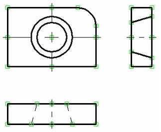
You should still be within the command "L: Construct Line". Point the cursor at and select the bottom line of the plan view. This way we can create a line parallel to the bottom-side one. Now, move the cursor to the newly created node and type <N>. This creates a line parallel to the selected one and passing through the specified node. Thus, the top and the side view become parametrically related. To witness this, call the construction line editing command "EC: Edit Construction". Try changing location of the left-side line of the side view. To do so, select it, move and fix in the new position. Note now that the corresponding line on the plan view moves accordingly. Construction of the conical hole on the plan view follows the same steps as on the side view. Select a vertical line while in the construction line creation command, and create four parallel lines tangent to the two circles. |
|
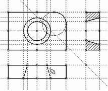
Now one can draw all graphic lines on the plan view. Use the command "G: Create Graphic Line" to draw the perimeter of the plan view. Next step is to apply the two dashed lines corresponding to the conical hole. Set the "HIDDEN" line type in the system toolbar. |
|
Then create the two dashed lines representing the conical hole. Now, let's create centerlines. Call "AX: Create Axis" command. Set the automenu option
|
|
Use |
|
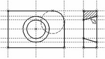
We recommend using specifically the right side of the part main view as the base line, and construct all the rest vertical lines with respect to it. In this way, the line-to-line distances will be positive which is preferable in some situations.
1. Call "EC: Edit Construction" command.
2. Selecting one particular line and typing <T> or pushing ![]() trims this selected line only.
trims this selected line only.
3. Using option ![]() trims all lines.
trims all lines.
4. If you want to revert to the infinite line setting, call the command "ST: Set Document Parameters":
Icon |
Ribbon |
|---|---|
|
Edit → Document → Document Parameters
|
Keyboard |
Textual Menu |
<ST> |
Customize > Document Parameters |
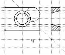
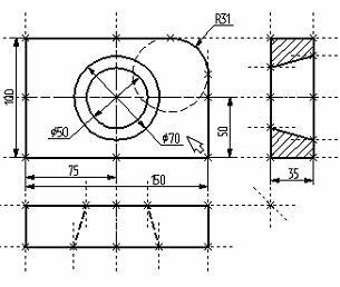
Go to the parameter «View|Construction Lines|Length» and set it to "Default infinite". Alternatively, enter the command "EC: Edit Construction", select desired lines, type <P> and specify an appropriate setting. The diagram shows a drawing with construction lines trimmed. It appears less crowded, although all necessary construction entities are present. By default, construction lines are not output to the printer or plotter, regardless of their length. |
|
Next, let's create the necessary dimensions on the drawing as follows.
1. First, let's create linear dimensions. Call the command "D: Create Dimension":
Icon |
Ribbon |
|---|---|
|
Draw → Title Block → Dimension |
Keyboard |
Textual Menu |
<D> |
Construct > Dimension |
One can select any pair of construction lines or graphic lines to create a linear or angular dimension. Select the two outermost lines on the main view by ![]() . This starts rubberbanding of a dimension following the cursor motion. To change any dimension parameter, type <P> or push the
. This starts rubberbanding of a dimension following the cursor motion. To change any dimension parameter, type <P> or push the ![]() button in the automenu. The dimension parameters dialog box will appear on screen. Specify the desired parameters, close the dialog, and fix dimension placement with
button in the automenu. The dimension parameters dialog box will appear on screen. Specify the desired parameters, close the dialog, and fix dimension placement with ![]() . To change the size of the dimension string font, use the command "ST: Set Document Parameters", the "Font" tab. The font parameters can be specified on this tab for the elements that did not have such parameters set originally.
. To change the size of the dimension string font, use the command "ST: Set Document Parameters", the "Font" tab. The font parameters can be specified on this tab for the elements that did not have such parameters set originally.
2. Repeat the steps of the item 1 for the rest of the linear dimensions.
3. Diameter and radius dimension creation is also straightforward. While in "D: Create Dimension" command, move the cursor to a circle to be dimensioned, and type <C> or click ![]() . The circle gets selected, and a dimension begins rubberbanding after the cursor. Switch between the radius and diameter dimension types by typing <R> and <D> or picking
. The circle gets selected, and a dimension begins rubberbanding after the cursor. Switch between the radius and diameter dimension types by typing <R> and <D> or picking ![]() and
and ![]() buttons of the automenu as appropriate. Typing <M> loops through the possible witness/leader line configurations for the entity to be dimensioned. The <Tab> key handles the direction of the dimension leader line jog. Point the cursor at the desired location and press
buttons of the automenu as appropriate. Typing <M> loops through the possible witness/leader line configurations for the entity to be dimensioned. The <Tab> key handles the direction of the dimension leader line jog. Point the cursor at the desired location and press ![]() . The newly created dimension will be displayed on the screen. Repeat this procedure to dimension all circles.
. The newly created dimension will be displayed on the screen. Repeat this procedure to dimension all circles.
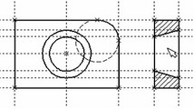
4. After finishing construction of all major elements, one can hide all construction entities using the command "SH: Set Levels":
Icon |
Ribbon |
|---|---|
|
Edit → Document → Levels |
Keyboard |
Textual Menu |
<SH> |
Customize > Levels |
This command controls visibility of various elements. An element visibility depends on the "level" at which it is residing.
Think of levels as transparent films with images drawn on them. The complete drawing consists of all of them overlapped. The system permits making one or more levels invisible, displaying only intended ones. A drawing may consist from up to 255 levels enumerated from -126 to 127.
All elements in T-FLEX CAD are automatically created on the level "0". One can re-assign any element to another level at any time. In our example, we did not change levels of any element; therefore, all created elements fell in the level "0".
After calling the command, a dialog box appears on screen that allows setting a range of visible levels for each element type of the model.
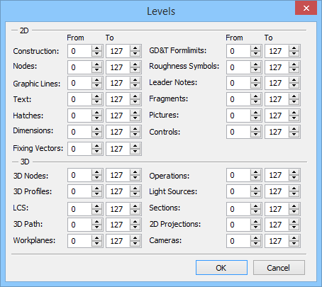
As appears on the diagram above, all elements are visible by default whose level is in the range from 0 to 127. Setting the low limit of the visible range to 1 for construction lines and nodes hides the construction lines and nodes, because they reside on the level 0 which is not within the new range. A simpler way to hide construction lines and nodes is to use a dedicated command. This command hides or shows all construction entities in the current window. It is preferable in the situations when hiding construction should not affect the document data, rather, the current window only. |
|
It is thus possible to open the same document in several windows, and have construction entities displayed in some windows, and hidden in others.
Call the command via
Keyboard |
Textual Menu |
Icon |
<Ctrl><Shift><C> |
View > Hide Construction |
|
5. Let's make a line of text containing the name of the drawing using command "TE: Create Text". Call the command via
Icon |
Ribbon |
|---|---|
|
Draw → Title Block → Text |
Keyboard |
Textual Menu |
<TE> |
Construct > Text |
In the automenu of the command, turn on the option:
|
<D> |
Create string text |
A text can be "snapped" to any construction entity on the drawing in order to have it move together with the drawing elements being modified.
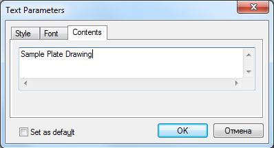
Move cursor to the intersection of the vertical centerline and the top line on the main view. Type <N> in order to snap the text to the node at the intersection. Move the cursor to the text placement point and press ![]() . The text editor window appears on screen. Type a line of text "Sample Plate Drawing" and push [OK] button.
. The text editor window appears on screen. Type a line of text "Sample Plate Drawing" and push [OK] button.
Should the text not be placed as intended, this can be corrected easily. Quit the text creation command. Point and click ![]() at the text. This automatically starts the editing command "ET: Edit Text". The selected text starts moving after the cursor. Locate it as desired and click
at the text. This automatically starts the editing command "ET: Edit Text". The selected text starts moving after the cursor. Locate it as desired and click ![]() .
.
To explicitly call the text editing command, use
Keyboard |
Textual Menu |
Icon |
<ET> |
Edit > Draw > Text |
|
In this case, select the text to be edited after launching the command.
There is another way of creating a text, which is typing it directly in the drawing area. To do so, enter the "TE: Create Text" command and set the option <Т> - "Create paragraph text" (icon ![]() ). Move the cursor to the intended location of the text and press
). Move the cursor to the intended location of the text and press ![]() . A rectangle starts rubberbanding on screen that defines the text box. Define the intended area and click
. A rectangle starts rubberbanding on screen that defines the text box. Define the intended area and click ![]() , then push the
, then push the ![]() icon. A blinking cursor will appear in the box. Make sure of the correct input locale and enter the intended text. Then push the
icon. A blinking cursor will appear in the box. Make sure of the correct input locale and enter the intended text. Then push the ![]() icon or <F5> key.
icon or <F5> key.
The drawing is now finished. One can try moving construction lines using construction editing command. When editing, fix line new placement by either using ![]() or specifying exact line location in the property window or parameters dialog (the latter accessible via the
or specifying exact line location in the property window or parameters dialog (the latter accessible via the ![]() pick). Note that the whole drawing, including dimensions, adequately responds to modifications. Changing diameters of the conical hole instantly reflects on the two other views. Hatches also adjust to their defining contours. Now one can easily witness the powerful capabilities brought in by the parametric technology.
pick). Note that the whole drawing, including dimensions, adequately responds to modifications. Changing diameters of the conical hole instantly reflects on the two other views. Hatches also adjust to their defining contours. Now one can easily witness the powerful capabilities brought in by the parametric technology.
From now, we will assign variables and expressions to the various drawing elements. Select the right-side line on the main view by clicking ![]() .
.
The line will get highlighted, along with the one it is dependent on by construction. Line editing command will automatically activate as well. The two parameters are displayed in the property window. The first one is the original distance, and the second is the current value according to the cursor position.
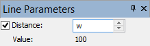
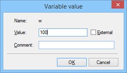
Since the line was originally created as parallel to the left side of the plate, the displayed distance is the distance between the right and the left side of the plate. Instead of a specific value, one can input a variable. Type a variable name "w" instead of the value and press <Enter> or [OK].
A new dialog window will appear requesting a confirmation for the new variable to be created.
Please note that the variable naming is case-sensitive. A variable "w" is not the same as "W".
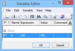
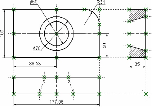
The created variable «w» and the value assigned for this variable can be seen in the window “Variables” located, by default, under the properties window. Point with a cursor at the number in the column “Expression”, press ![]() to enter the edit mode and specify the value for the variable, for example, «170». The line will move to a different location corresponding to the new value of the plate width.
to enter the edit mode and specify the value for the variable, for example, «170». The line will move to a different location corresponding to the new value of the plate width.
The same operations can be carried out in the dialog window of the command "V: Edit Variables":
Icon |
Ribbon |
|---|---|
|
Title Block → Additional → Variables |
Keyboard |
Textual Menu |
<V> |
Parameters > Variables |
Similarly, define a variable "H" as the distance from the base line to the top side of the main view. Select the line on the drawing by clicking ![]() and enter the variable name in the property window. Now there will be already two variables in the window “Variables”, and you can, by modifying their values, observe the change in the drawing.
and enter the variable name in the property window. Now there will be already two variables in the window “Variables”, and you can, by modifying their values, observe the change in the drawing.
Try making an expression. In the window “Variables” place the cursor in the field “Expression” of the variable «H» and press ![]() to enter the edit mode. Specify the expression «w/2» instead of the numerical value.
to enter the edit mode. Specify the expression «w/2» instead of the numerical value.
This means that the value of "H" will be equal to the half of "w". From now on, changing just the value of "w" will automatically reflect on the value of "H".
Next, let's assign an "R" variable to the radius of the circle defining the fillet at the right-top corner of the plate. Select the circle on the drawing by ![]() . In the property window specify the radius as "R" variable. After confirming its creation, in the window “Variables” set the variable to the following expression: w < 100 ? 0 : 6
. In the property window specify the radius as "R" variable. After confirming its creation, in the window “Variables” set the variable to the following expression: w < 100 ? 0 : 6
This expression means that "R" equals 0 when "w" is less than 100, and equals 6 otherwise.
Let's briefly explain the syntax of the expression. Its members are described as follows.
< - is the "less than" sign
? - means "then", "in such a case"
: - means "else", "otherwise"
The complete expression is written as
R = w < 100 ? 0 : 6
The value of "R" equals 0, if "w" < 100, and equals 6 for any other value of "w". Therefore, there are only two possible values of "R" - either "0" or "6".
Check this on your drawing. Try setting "w" values greater or less than 100, and watch what's happening. Note that when the radius of the fillet equals 0, then the radial dimension automatically disappears. The system does it for the user.
Therefore, one can create a variety of relations between variables, including quite complex ones, using just a few basic terms. You will get to know all capabilities of the variables functionality in later chapters.
Creating sketch, non-parametric drawing
We will use the same familiar drawing example of the plate with a conical hole. Let's begin with constructing the main view. Thereafter, we will create two projections, the "Left Side View" and the "Plan View", using object snapping mechanism.
In this case, all construction is done using the command "SK: Create Sketch". Call the command via
Icon |
Ribbon |
|---|---|
|
Draw → Sketch |
Keyboard |
Textual Menu |
<SK> |
Construct > Sketch |
This command can be used to create either a sketch (nonparametric drawing) or a parametric drawing in the automatic parameterization mode. Since we are going to create specifically a sketch, please make sure that the automatic parameterization icon is switched off on the "View" toolbar
![]() Automatic parameterization on/off
Automatic parameterization on/off
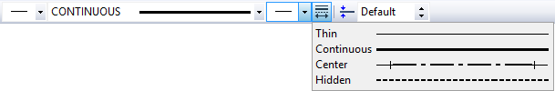
When creating a sketch, object snaps are widely used. The control over snaps is performed with the "Snaps" toolbar.
To access this toolbar, press the icon ![]() on the toolbar “View”. All snaps turned on by the present moment correspond to the toolbar icons which have been pressed.
on the toolbar “View”. All snaps turned on by the present moment correspond to the toolbar icons which have been pressed.
By default, all snaps are enabled, with the respective icons pushed on this toolbar.
To turn off a pushed option, point at and click ![]() on the respective icon. To turn off snapping completely, set the option:
on the respective icon. To turn off snapping completely, set the option:
|
Clear all sketch Snaps |
Unsetting this option sets all snaps on. In our exercise, the following snaps will be used:
|
Line Midpoint |
|
Horizontal / Vertical |
|
Orthogonal |
|
Line Intersection |
|
Horizontal/Vertical tangent |
Push these icons on the "Snap" toolbar. The object snaps can also be managed within the command "SO: Set System Options", using "Snap" tab.
When creating line segments, arcs and circles, the point coordinates can be defined by simply clicking ![]() in the drawing area. To specify exact node coordinates, one can use the property window.
in the drawing area. To specify exact node coordinates, one can use the property window.
The two options are turned on automatically in the automenu while within the sketch creation command:
|
<J> |
Continuous creation |
|
<S> |
Line |
The first icon allows drawing continuously, so that the end of a just created line becomes the start of the new line. This mode will stay active until the user turns it off by pointing at the icon and clicking ![]() . We recommend keeping this option on for speedy sketching. The other option sets the segment input mode. A black triangle in the bottom-right corner of the icon marks availability of more options. To access these encapsulated options, press
. We recommend keeping this option on for speedy sketching. The other option sets the segment input mode. A black triangle in the bottom-right corner of the icon marks availability of more options. To access these encapsulated options, press ![]() and hold a bit longer, and a menu of options will appear.
and hold a bit longer, and a menu of options will appear.
Attention: the automenu may display any of the encapsulated option icons in the given position. Usually this is the icon of the last used option among the encapsulated set.
In "Sketch" automenu, each set of encapsulated options corresponds to a group of actions related to same-type element creation, such as creating segments, arcs, or circles.
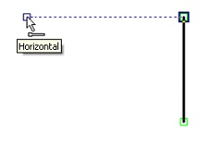
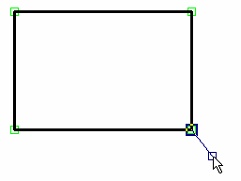
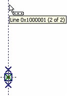
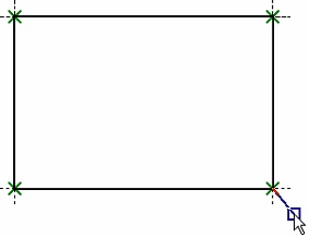
The cursor on screen appears as a little square. Move the cursor to the intended location at the bottom-right corner of the main view, near the middle of the screen, and press ![]() . This creates the first node of a line segment and starts rubberbanding the segment to be created. At the same time, the fixed coordinates of the first point are displayed in the property window.
. This creates the first node of a line segment and starts rubberbanding the segment to be created. At the same time, the fixed coordinates of the first point are displayed in the property window.
While sketching, consider leaving sufficient margins. This space will later be used for creating dimensions.
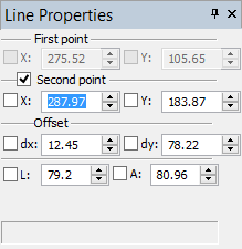
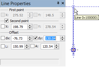
Move the cursor upward. Note that the coordinates of the cursor are dynamically updated in the property window, along with the vertical and horizontal shifts from the start node of the segment. We can use the property window for specifying exact location of the segment end. The end node can be defined in several ways. One way is to enter absolute Cartesian coordinates (X, Y) of the segment end node. Another way is specifying X and Y shifts of the end node from the segment start (dx, dy). Yet another way is to define the end of the segment in polar coordinates, or as a combination of the other ways. |
|
Let's create the end of the segment by specifying its shift from the start point. Make "dx" value equal to 0, and "dy" parameter equal to 100. The parameters "X" и "Y" will instantly update with the absolute coordinates of the segment end and get checkmarked. Checkmarking locks the value of the respective coordinate in spite of cursor movements. The end node of the segment will be displayed in the drawing window per the entered coordinate values. |
|
To complete the end node input, press [Enter] or click |
|
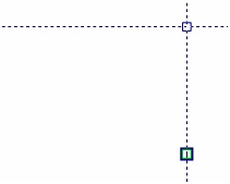
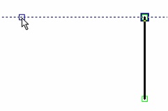
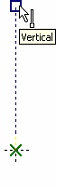
To lock this snap, press <Space> bar. Then, a horizontal helper line will be displayed passing through the node snapped to. The cursor will keep sliding along this helper line as an unattached node. The same effect can be achieved by setting the "dx" shift to 0 in the property window and locking the X coordinate with the checkmark. |
|
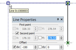
Place cursor on the side of the segment intended direction. Type the value of the "dx" shift for the end node of the segment being created in the property window. In our case, this value represents the width of the part and is equal to -150, while "dy" equals 0. The new segment will be created upon confirmation by pressing [Enter] or |
|
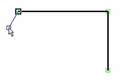
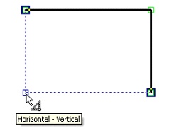
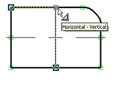
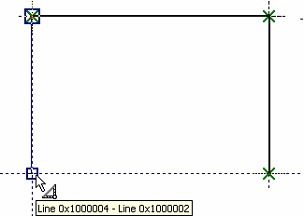
You are still within the segment creation mode. For further construction, you need to move the cursor downward to a point where snapping occurs to both horizontal and vertical constraints simultaneously. This will be indicated by a special glyph next to cursor and pop-up help message. Press |
|
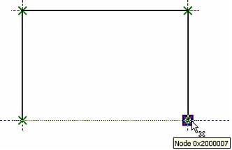
Move the cursor right to snap at the very first created node, as indicated by a glyph and the pop-up help, and press |
|
Now you are still within continuous segment input mode, with snapping active but no line rubberbanding after the cursor.
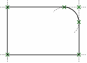
The next step is to round the corner of the plate. To do so, set the option
![]() <Ctrl+A> Fillet
<Ctrl+A> Fillet
This option belongs to an encapsulated set and may not necessarily be displayed in the automenu. Instead, it may be under the fillet/chamfer icon group (see explanation above).
Once the option is set, the property window changes appearance. Now it provides the input box for the fillet radius. Set the radius value equal to 31.
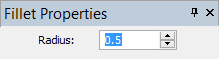
What is left now is to select two segments to be filleted. In our case, it is the top and the right-side segments of the plate. Once the second segment is selected, the fillet is created, and the segments trimmed appropriately.
Now let's draw the conical hole on the main view. To do so, let's create two centerlines whose intersection will define the exact location of the center of the hole. Set the option
![]() <S> Line
<S> Line
Once this is set, rubberbanding resumes with a line attached to the last created node. Reject this line by clicking ![]() . To create centerlines, set the appropriate line type. Set the line type to DASHDOT in the system toolbar or in the graphic line parameters of the dialog box. Call the dialog box by
. To create centerlines, set the appropriate line type. Set the line type to DASHDOT in the system toolbar or in the graphic line parameters of the dialog box. Call the dialog box by
![]() <Р> Set Graphic line parameters
<Р> Set Graphic line parameters
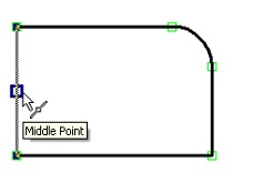
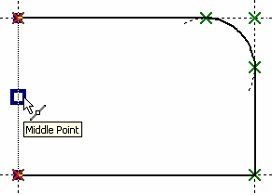
Then move the cursor to the left graphic line segment to get vertical snapping to one of the segment nodes, and slide the cursor along the segment to its midpoint. When the cursor reaches the midpoint, the glyph beside the cursor will change to indicate this, along with the pop-up help. |
|
Press |
|
Press ![]() , creating a centerline and a node. Rubberbanding resumes from the latest node. As we do not intend to construct another line through this node, quit rubberbanding with
, creating a centerline and a node. Rubberbanding resumes from the latest node. As we do not intend to construct another line through this node, quit rubberbanding with ![]() . Then follow the same steps to create the vertical centerline, beginning at the bottom segment.
. Then follow the same steps to create the vertical centerline, beginning at the bottom segment.

Now, let's create circles. First, reset the line type to CONTINUOUS by selecting in the system toolbar or in the command parameters dialog box. Call the dialog by typing <P>. Then pick the option
![]() <O> Circle By Center And Radius
<O> Circle By Center And Radius
This is also an encapsulated option that may not be shown on the automenu, rather, be within a group of options. After activating the option, move the cursor to the intersection of the two centerlines. Both centerlines will get highlighted, and the cursor will gain a glyph and a pop-up help of the graphic line intersection snap. Press |
|
Enter the value of the radius of the smaller circle of the cone equal to 25 in the property window, and press [Enter] key. A full circle is now fixed on screen. Now you are still in the circle creation mode. Select the node at the two centerlines intersection and create a circle of a bigger radius, 35. This mostly completes creation of the main view of the part. |
|
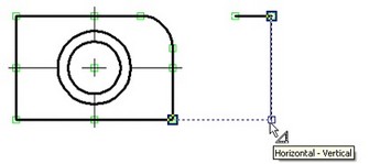
Now, let's construct the left side view. Again, set the line creation mode via the |
|
Click here ![]() , and move the cursor horizontally rightwards. In the property window, set the end node shifts. Set the Х equal to 35, Y to 0. Press [Enter] or
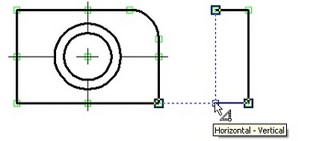
, and move the cursor horizontally rightwards. In the property window, set the end node shifts. Set the Х equal to 35, Y to 0. Press [Enter] or ![]() . The new segment will be fixed on screen, and rubberbanding resume from the last created node. Next, move the cursor vertically downward maintaining the "vertical" snap, up to the point when snapping occurs with a node of the bottom line of the main view. Click there
. The new segment will be fixed on screen, and rubberbanding resume from the last created node. Next, move the cursor vertically downward maintaining the "vertical" snap, up to the point when snapping occurs with a node of the bottom line of the main view. Click there ![]() , then move the cursor leftwards to snap against the left end of the top segment.
, then move the cursor leftwards to snap against the left end of the top segment.
Click ![]() . Now close the perimeter of graphic lines by moving cursor to the first created node on this view, and clicking
. Now close the perimeter of graphic lines by moving cursor to the first created node on this view, and clicking ![]() , and then
, and then ![]() .
.
One-degree-of-freedom snaps can be locked by pressing <Space> bar.
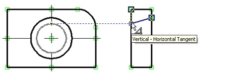
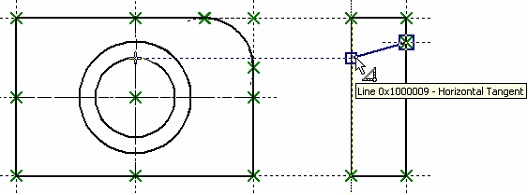
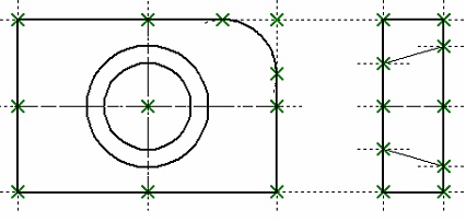
Next, we need to create the image of the conical hole on the side view. Without quitting the current command, move the cursor to the right-side segment of the side view, and move along the segment until it snaps to horizontal tangency against the top of the bigger circle.
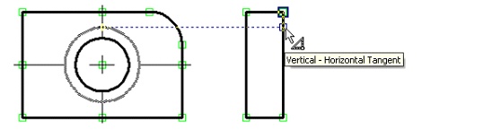
Click ![]() at this spot, then move the cursor to the left segment of the side view and locate so to get it snapped against the smaller circle.
at this spot, then move the cursor to the left segment of the side view and locate so to get it snapped against the smaller circle.
Click ![]() , and a segment will be created, with rubberbanding resuming from its end node. For now, quit rubberbanding by clicking
, and a segment will be created, with rubberbanding resuming from its end node. For now, quit rubberbanding by clicking ![]() . Then construct the lower segment of the hole view in the same way. Next, using already familiar snapping constraints, construct the centerline, setting the line type to DASHDOT in the graphic line parameter dialog box (the key <Р>) or in the system toolbar.
. Then construct the lower segment of the hole view in the same way. Next, using already familiar snapping constraints, construct the centerline, setting the line type to DASHDOT in the graphic line parameter dialog box (the key <Р>) or in the system toolbar.
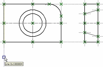
Proceed with the plan view. This view can be created in the same way as the side view. However, for deeper exploration of non-parametric drawing capabilities, we will follow a different approach. Set the option
![]() <D> Parallel Line
<D> Parallel Line
This is an encapsulated option in the segment creation group. If this icon is not displayed in the automenu, find it under one of the group icons marked with a black triangle (see explanation above).
Once this option is set, the cursor starts rubberbanding an auxiliary infinite line parallel to the last created segment. The reference segment is highlighted. The current reference suites us. Otherwise, we would reject the system-selected segment with ![]() and select an intended one to construct a parallel line. Make sure the line type is back to CONTINUOUS in the graphic line parameter dialog (the key <P>) or in the system toolbar. Move the cursor to get a snap against a node of the main view, and click
and select an intended one to construct a parallel line. Make sure the line type is back to CONTINUOUS in the graphic line parameter dialog (the key <P>) or in the system toolbar. Move the cursor to get a snap against a node of the main view, and click ![]() . A node will be created at this point, and the auxiliary line will get fixed. Slide the cursor along the line up to the point of another vertical snapping, and again click
. A node will be created at this point, and the auxiliary line will get fixed. Slide the cursor along the line up to the point of another vertical snapping, and again click ![]() .
.
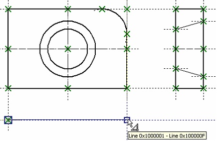
Thus, we have created the top segment of the plan view. A new auxiliary line starts rubberbanding after the cursor, parallel to the newly created graphic segment, as indicated by highlighting. Move the cursor down, and set the desired distance, equal to 35, in the property window, thus defining the thickness of the plate. This will fix the auxiliary line with respect to the reference segment. Slide the cursor along the line, locating as shown on the diagram.
Click ![]() , fixing the start node of the segment being created. Slide the cursor rightwards to get vertical snap against the end node of the reference segment, and again click
, fixing the start node of the segment being created. Slide the cursor rightwards to get vertical snap against the end node of the reference segment, and again click ![]() . The bottom segment will be created. At this moment, parallel line rubberbanding resumes. Now, set the option
. The bottom segment will be created. At this moment, parallel line rubberbanding resumes. Now, set the option ![]() , thus switching to normal continuous line input mode. A line will start rubberbanding, attached to the last created node. Move the cursor upward to the top segment node, and click
, thus switching to normal continuous line input mode. A line will start rubberbanding, attached to the last created node. Move the cursor upward to the top segment node, and click ![]() , and then
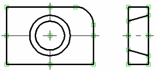
, and then ![]() . Next, connect the left ends on the plan view with another segment. Create the centerline and the lines of the conical hole projection in the same way as on the side view. Doing so, maintain the appropriate line types.
. Next, connect the left ends on the plan view with another segment. Create the centerline and the lines of the conical hole projection in the same way as on the side view. Doing so, maintain the appropriate line types.
What is left now is to apply hatch on the side view. Call the command "H: Create Hatch":
![]() <Н> Create Hatch
<Н> Create Hatch
Set the option
![]() <A> Automatic Contour search mode
<A> Automatic Contour search mode
Then move the cursor to the top portion of the side view, place it in the middle of the area to be hatched, and click ![]() . The closed contour will be highlighted. Now move the cursor to the lower portion of the view, and similarly select the other contour to be hatched. Then pick the
. The closed contour will be highlighted. Now move the cursor to the lower portion of the view, and similarly select the other contour to be hatched. Then pick the ![]() button.
button.
Now, let's create the necessary dimensions on the drawing. Dimensions are created on a sketch in the same way as on a parametric drawing. One can select graphic lines instead of construction lines in this case. Let's skip the detailed description of this functionality, as it was described in depth as part of the main drawing technique.
This completes creation of the non-parametric drawing. Further modification of its elements will not affect the whole drawing. One would have to modify each view separately. The elements of such a drawing cannot be related by variables. All other functionalities such as use of visibility levels, layers, hide/show construction entities, etc. are fully supported.
Creating a parametric drawing in the automatic parameterization mode
We will use the same drawing as an example. The sequence of constructions will be the same as described in the previous section of this chapter.
When working in the automatic parameterization mode, we will be creating only graphic lines (as when constructing a sketch). Meanwhile, the system will be automatically "slipping" nodes and construction lines with parametric relations underneath those graphic lines. What constructions to create and what dependencies to use in relations is determined by the system based on the user-selected snaps and parameters defined in the command's property window when creating sketched lines.
Call the command "SK: Create Sketch". Make sure that the following snaps are enabled:
|
Construction |
|
Line Midpoint |
|
Horizontal/Vertical |
|
Orthogonal |
|
Graphic Line Intersection |
|
Horizontal/Vertical tangent |
To create a parametric drawing, the automatic parameterization mode must be turned On in the system. This mode is enabled with the icon on the "View" bar:
|
Automatic parameterization On/Off |
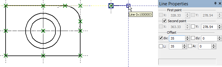
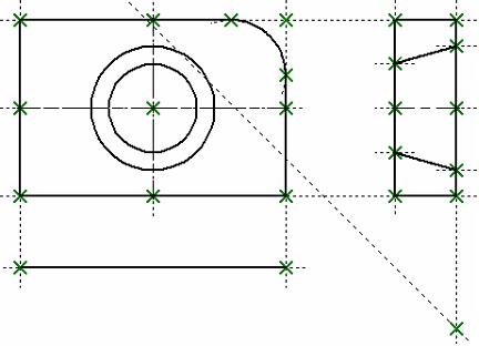
We will start with creating the main view of the plate. If necessary, enable the line segment creation option ![]() in the command's automenu (if desired). Create the first point of the segment, corresponding to the lower-right corner of the plate's main view. Please note that it was not a free node that was created at the location of the click, rather, there are two crossed lines (vertical and horizontal), and a node at their intersection.
in the command's automenu (if desired). Create the first point of the segment, corresponding to the lower-right corner of the plate's main view. Please note that it was not a free node that was created at the location of the click, rather, there are two crossed lines (vertical and horizontal), and a node at their intersection.
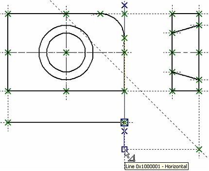
For the second node of the segment, define the Y-axis offset (100) in the properties window. The cursor will start moving along a horizontal auxiliary line. Move it to the vertical construction line going through the first segment node. When the snap to the latter line engages ("Line …"), click ![]() . As a result, the second node of the created segment will also be constructed as snapped. It will lie on the intersection of the vertical line created at the time of constructing the first node, and a line parallel to the horizontal line of the first node.
. As a result, the second node of the created segment will also be constructed as snapped. It will lie on the intersection of the vertical line created at the time of constructing the first node, and a line parallel to the horizontal line of the first node.
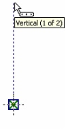
Please note, that, when selecting a snap, the system may offer the vertical snap to the first segment node rather than snapping to the line (the order of displaying snaps is determined by the settings in the command "SO: Set System Options"). To select the desired snap, do the following: briefly rest the cursor at the location of the snap activation. After a brief while, the cursor will change its shape: the mark ![]() and a tooltip will appear next to it, showing the total number of object snaps found at this point. Using the mouse wheel, you can scroll through those snaps. In the ongoing construction, select the desired snap from the list of possible ones at a given point using the same method.
and a tooltip will appear next to it, showing the total number of object snaps found at this point. Using the mouse wheel, you can scroll through those snaps. In the ongoing construction, select the desired snap from the list of possible ones at a given point using the same method.
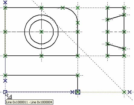
Create the second, horizontal, line segment with the length 150. When constructing it, specify the desired offset along the X-axis and use a snap to the line again. If all was done correctly, then the created line segment will lie on the line created at the time of constructing the second node of the previous segment. Meanwhile, the second node of the current segment will be constructed as one lying on the intersection of the same line and a new line parallel to the very first vertical line.
The third line segment, again vertical, is constructed by snapping to two existing lines at once.
The fourth segment must be closing the described rectangle. After that, move the cursor rightward up to the first created node, as indicated by a special mark in the dynamic tooltip, and click ![]() . This completes the base for the part's main view.
. This completes the base for the part's main view.
Please note, that the resulting drawing we obtained is the same as when constructing a parametric drawing by the conventional approach (as was described in the first section of this chapter). Just like when creating a sketch, to create a fillet one would need to quit the continuous line input mode (using ![]() ). To create the fillet, let's use the option
). To create the fillet, let's use the option ![]() . After activating the option, set the fillet radius equal to 31 in the properties window. After that, select two segments, at whose intersection the fillet needs to be constructed (the top and the right-hand-side segments of the plate) or the node (the rectangle vertex) at their intersection. This will result in constructing a graphic line – a circular arc with a "slipped underneath" construction line-circle. Just like when creating a common sketch, the extra pieces of the fillet segments will be automatically trimmed. Next, we will create the image of the conical hole.
. After activating the option, set the fillet radius equal to 31 in the properties window. After that, select two segments, at whose intersection the fillet needs to be constructed (the top and the right-hand-side segments of the plate) or the node (the rectangle vertex) at their intersection. This will result in constructing a graphic line – a circular arc with a "slipped underneath" construction line-circle. Just like when creating a common sketch, the extra pieces of the fillet segments will be automatically trimmed. Next, we will create the image of the conical hole.
We will start with creating the axes. To create the axes, enable the ![]() option again. Set the "Axis" line type in the system panel or in the graphic line parameters (the option
option again. Set the "Axis" line type in the system panel or in the graphic line parameters (the option ![]() ).
).
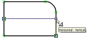
Move the cursor to the middle of the left-hand-side segment of the plate's main view image. Construct the first node of the axis using the line midpoint snap. Move the cursor horizontally to the right-hand-side segment of the image and stop it at the intersection of the two lines as shown on the figure. Click ![]() . The created segment will lie on the line that divides the segment (the left-hand side of the main view) in the 0.5 ratio.
. The created segment will lie on the line that divides the segment (the left-hand side of the main view) in the 0.5 ratio.
Similarly construct the vertical axis.

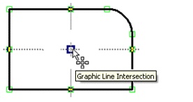
Now, let's create the circles. Set the normal graphic line type. After that, select the option ![]() . Move the cursor to the intersection of the axial lines, wait until the tooltip appears indicating the available snapping to the intersection lines. Click
. Move the cursor to the intersection of the axial lines, wait until the tooltip appears indicating the available snapping to the intersection lines. Click ![]() right there. A rubberbanding circle will appear on the screen. Set the radius value equal to 25 for the smaller circle of the conical hole and click
right there. A rubberbanding circle will appear on the screen. Set the radius value equal to 25 for the smaller circle of the conical hole and click ![]() or press the button [Enter]. Similarly construct the second circle with the radius equal to 35.
or press the button [Enter]. Similarly construct the second circle with the radius equal to 35.
Please note that the construction result is not just free graphic lines representing the circles. The system constructed them as lying on the construction lines-circles.
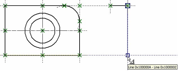
Now let's create the left view. To do that, enable the segment creation mode again (the option ![]() ). If the system offers creating a segment from the last created node, refuse that by right-clicking
). If the system offers creating a segment from the last created node, refuse that by right-clicking ![]() . Move the cursor to the right-hand side of the drawing and set it so as to maintain the snap to the top line of the main drawing view.
. Move the cursor to the right-hand side of the drawing and set it so as to maintain the snap to the top line of the main drawing view.
Click there ![]() . The first node of the new segment will be constructed as lying on the selected construction line.
. The first node of the new segment will be constructed as lying on the selected construction line.
Move the cursor horizontally rightward. In the properties window set the offset of the second point along the X-axis equal to 35. Then move the cursor so as to pick the snap to the top line of the main view. Click ![]() . As a result, the second segment node will also lie on the top line of the main view at the distance 35 from the first node.
. As a result, the second segment node will also lie on the top line of the main view at the distance 35 from the first node.
Then move the cursor downward vertically to the last created node up until a snap to two lines appears on the screen.
Click ![]() and move the cursor leftwards till snapping to two other lines.
and move the cursor leftwards till snapping to two other lines.
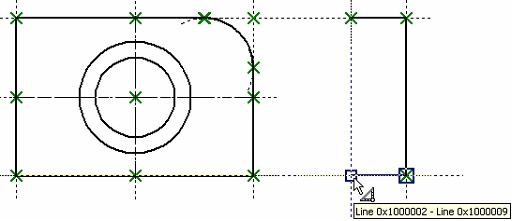
Click ![]() . Now, close the created graphic lines by moving the cursor to the first created node on this view, and click
. Now, close the created graphic lines by moving the cursor to the first created node on this view, and click ![]() , then
, then ![]() (to cancel the mode of continuous line input).
(to cancel the mode of continuous line input).
After that, we will create the lines belonging to the conical hole, on the left view. Move the cursor to the right-hand-side segment of the left view, and then move it along that segment up until establishing the relation between the line underlying that segment and the greater circle. Click ![]() right there.
right there.
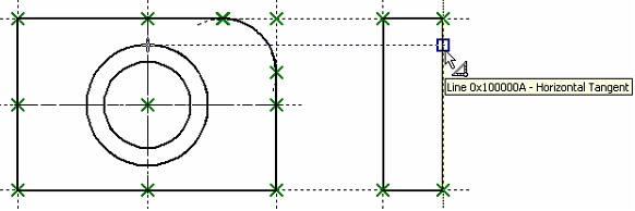
Move the cursor to the left-hand-side segment of the same view so as to establish the relation between the smaller circle and the line underlying that segment. Click ![]() .
.
As a result, a segment will be created. No construction line will be underlying that segment. Nevertheless, each segment node will be constructed as a node at an intersection of the selected line and the line tangent to the circle.
Next, use the same method to construct the lower line of the conical hole. Then create the centerline by snapping to the middles of the lateral sides of the left view. Do not forget to also set the dash-dot line type in the graphic line parameters (the option ![]() ) or on the system panel.
) or on the system panel.
Let's proceed to creating the top (plan) view. We will create it a little bit different then when creating a simple sketch. We will not use the option of constructing a parallel segment. Now there is no practical necessity in defining that particular relation. When using the automatic parameterization mode, the use of that option will make the system try to create a construction line beneath the segment parallel to a line beneath another segment. As a result, relations would be created that we didn't need. Therefore, we will continue using the option ![]() .
.
Do not forget to reset the normal line type after finishing the creation of the centerline (in the graphic line parameters or on the system panel).
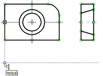
Move the cursor to the drawing area below the main view so as to invoke the desired relation with the line of the main view. Click ![]() . The first segment node will be created as lying on the intersection of the main view line and the horizontal line.
. The first segment node will be created as lying on the intersection of the main view line and the horizontal line.
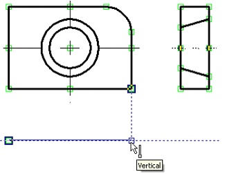
Next, move the cursor rightward up until hitting the snap to another line of the main view. Click ![]() again. We have just created the upper segment of the top view.
again. We have just created the upper segment of the top view.
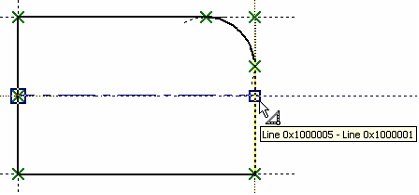
Next, we will have to temporarily quit the sketching command. The reason for that is that it is impossible to create a relation between the left view and the top view by the common means of automatic parameterization. Such relation can be achieved only by various workaround methods (for example, introducing variables as the parameters of the segments being created). But we will simply use the command "L: Construct Line" and create an auxiliary line at the angle of 45° to the outer lines of the left view and top view (just as we did in the conventional creation of the parametric drawing).
So go ahead and call the command "L: Construct Line". With the help of the option ![]() , construct a line – the symmetry axis between the left-hand-side vertical line of the left view and the horizontal line of the top view. Place the cursor at the intersection point of the created line and the right-hand-side vertical line of the left view, and then press the button <Space>.
, construct a line – the symmetry axis between the left-hand-side vertical line of the left view and the horizontal line of the top view. Place the cursor at the intersection point of the created line and the right-hand-side vertical line of the left view, and then press the button <Space>.
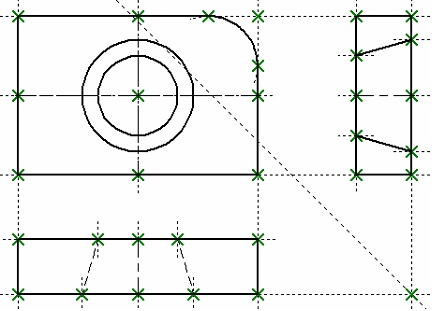
After that, call the command "SK: Create Sketch" again. We will create the next segment of the top view. Select the end node of the last created segment as the first node of the next segment. Then move the cursor up until reaching the intersection between the line and the horizontal through the node as shown on the figure. Fix the achieved point by clicking ![]() .
.
The next segment is constructed by snapping to two lines.
Next we need to close the created graphic lines of the top view by moving the cursor to the first created node of the view and clicking ![]() , followed by
, followed by ![]() (to cancel the continuous line input mode).
(to cancel the continuous line input mode).
Create the centerline and the lines defining the conical hole (just like that on the left view).
Create the hatch on the left view and the dimensions in the same way as in the previous cases.
This completes the creation of a parametric drawing in the automatic parameterization mode. From now on, such drawing will behave just as a common parametric drawing.
To test, move the cursor to the segment that makes up the left border of the main view, and click ![]() . The command will be launched to edit the selected graphic line. If you click
. The command will be launched to edit the selected graphic line. If you click ![]() on the line once again, the system will automatically go into the command of editing the construction line underlying this graphic line. Move the line around, define the new position by
on the line once again, the system will automatically go into the command of editing the construction line underlying this graphic line. Move the line around, define the new position by ![]() . The width of the plate main view shall automatically change. Besides that, the top view should change as well, since it was constructed by snapping to the lines of the front view.
. The width of the plate main view shall automatically change. Besides that, the top view should change as well, since it was constructed by snapping to the lines of the front view.
Similarly, try to edit the position of the right boundary of the main view. In this case, the entire plate drawing will move. Try the same with other drawing elements, including circles. As construction elements are moved, the shape and dimensions of the plate will be changing so as to maintain the relations defined by the construction.
This completes the brief introductory course. Please feel free to refer to the rest of T-FLEX CAD documentation for detailed description of various system functionalities.