Graphic Lines |
  
|
Graphic Lines |
|
Graphic lines are the base graphic elements that constitute the drawing image. The analogy for the graphic lines found in conventional drafting is the lines drawn in ink. Graphic lines are created based on construction lines and nodes. By "lines", we mean straight or curved line entities described below.
The various types of graphic lines can be defined by:
A line segment between two nodes. The graphic line limits are defined by the location of these nodes.
A full construction entity. This graphic line can only be defined by the underlying construction entity. The construction entity can be of any type except straight line as the latter is infinite.
A portion of construction entity between two nodes. This type of graphic entity is defined by the underlying shape-defining construction entity and two nodes defining the line limits.
Graphic entities can be created with user-defined line types. See details in the chapter "Creating Custom Lines and Hatches".
Creating graphic lines
Graphic lines are created in the command "G: Create Graphic Line". Call the command via:
Icon |
Ribbon |
|---|---|
|
Draw → Draw → Graphic Line |
Keyboard |
Textual Menu |
<G> |
Draw > Graphic Line |
On entering the command, the following options will be available in the automenu:
|
<Ctrl><F> |
Free mode on/off toggle |
|
<P> |
Set Graphic line Parameters |
|
<Alt+P> |
Copy Properties from Existing Element |
|
<Tab> |
Change arc direction |
|
<N> |
Select ending Node of Graphic line |
|
<L> |
Select straight Construction Line |
|
<C> |
Select Construction circle |
|
<E> |
Select full Ellipse Contour |
|
<S> |
Select full Spline or Polyline Contour |
|
<Q> |
Creation of graphic lines between two intersections of construction lines |
|
<BkSpace> |
Delete last Contour segment |
|
<F4> |
Execute Edit Graphics command |
|
<Esc> |
Cancel selection (available only when selecting a construction entity) |
|
<Esc> |
Exit command |
To create a segment:
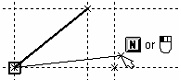
Select start node. If the selected node is on the intersection of several lines, then use the <L> option for specifying the line to apply graphics at. If upon typing <L> key the construction line is not highlighted, the selected node may not belong to the line. This means, a wrong node was selected.
Select end node. This completes creation of the graphic line between two nodes.
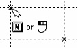
After creating a segment, the end node stays highlighted and becomes the start node for the next graphic line. If you want to create a graphic line starting elsewhere, press <Esc> or ![]() for canceling the current node selection.
for canceling the current node selection.
To define the start or end point of a graphic entity, simply place the cursor at the desired location and click ![]() . In "constrained" drawing mode, clicking
. In "constrained" drawing mode, clicking ![]() selects the node at the nearest intersection of construction entities, if exists; otherwise, a node will be created at this intersection and then get selected. In "free" drawing mode, either a new node is created, or an existing one is selected. An existing node is selected if the graphic cursor is within the "finding" zone around the node. The size of this zone is defined by the parameter "Node join distance" in the command "Customize|Options…|Preferences". The size is defined in pixels.
selects the node at the nearest intersection of construction entities, if exists; otherwise, a node will be created at this intersection and then get selected. In "free" drawing mode, either a new node is created, or an existing one is selected. An existing node is selected if the graphic cursor is within the "finding" zone around the node. The size of this zone is defined by the parameter "Node join distance" in the command "Customize|Options…|Preferences". The size is defined in pixels.
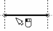
Automatic Creation of Graphic Line between Two Intersections of Construction Lines
In the Drawing|View command there is a mode of creation of graphic lines between two intersections of construction lines.
To use this option, it is required to press the ![]() button, move cursor to the construction line (line, circle, ellipse, spline, polyline) that is intersecting with other construction lines and press
button, move cursor to the construction line (line, circle, ellipse, spline, polyline) that is intersecting with other construction lines and press ![]() . Depending on location of the cursor the system finds the two nearest points of intersection of construction lines and creates the graphic line and nodes on its ends. When several lines are intersected at one point, the node is created between the lines that are created earlier than the others.
. Depending on location of the cursor the system finds the two nearest points of intersection of construction lines and creates the graphic line and nodes on its ends. When several lines are intersected at one point, the node is created between the lines that are created earlier than the others.

If, in this mode, by pressing the left button of the mouse we translate the cursor along the construction line, the construction line being created will automatically be continued (or shortened) in the desired direction.
Double clicking on the construction line will lead to creation of the graphic line on the entire construction line (except the straight line).
If there is graphic line already created with the help of this option, you can’t create line of the same color on the same place again. If necessary, you can change graphic line color or hide previously created line.
The ![]() option works similar to the click
option works similar to the click ![]() , however, unlike the latter, it only allows selection of existing nodes. New nodes won't be created.
, however, unlike the latter, it only allows selection of existing nodes. New nodes won't be created.
The options ![]() ,
, ![]() ,
, ![]() and
and ![]() allow selecting construction entities of the respective types. The option behavior depends on the current state (whether there is already a pre-highlighted node or construction line). The following is the way to create a full curve: Select a respective construction entity by typing <C>, <E> or <S>, in a state when no node is selected.
allow selecting construction entities of the respective types. The option behavior depends on the current state (whether there is already a pre-highlighted node or construction line). The following is the way to create a full curve: Select a respective construction entity by typing <C>, <E> or <S>, in a state when no node is selected.
To create a graphic line as a segment of the underlying construction line, do the following:
1.Select the start node for the segment (arc).
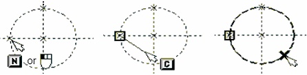
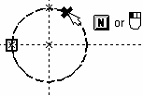
2.Select the intended construction entity. If a construction line does not get selected, that means the selected node does not belong to the line, and the arc can't be created starting from this node.
3.Select the end node of the segment (arc).
Then the arc will be created from the start to the end node. Please keep in mind that closed curves, such as a circle, are divided by two nodes into two arcs. The arc will be created nearest to the cursor at the time of selecting the end node.
Switching drawing mode. "Free" and "constrained" drawing modes
The option ![]() /
/![]() allows switching between the two modes of creating the construction elements – nodes. One of these is the "constrained" drawing mode (recommended), in which the nodes are created at intersections of construction entities only. The other is "free" drawing mode, in which the nodes are not related to other construction elements and their location is defined solely by the absolute coordinates of the drawing. The same drawing may contain both "free" and "constrained" nodes. Nodes may be created automatically while creating graphic entities. Therefore, it is important to know what drawing mode is currently set. The option icon in the automenu and the buttons on the "Modes" toolbar are not only for switching the mode. They also indicate the current mode. The
allows switching between the two modes of creating the construction elements – nodes. One of these is the "constrained" drawing mode (recommended), in which the nodes are created at intersections of construction entities only. The other is "free" drawing mode, in which the nodes are not related to other construction elements and their location is defined solely by the absolute coordinates of the drawing. The same drawing may contain both "free" and "constrained" nodes. Nodes may be created automatically while creating graphic entities. Therefore, it is important to know what drawing mode is currently set. The option icon in the automenu and the buttons on the "Modes" toolbar are not only for switching the mode. They also indicate the current mode. The ![]() icon in the automenu indicates that the "constrained" drawing mode is active, while the icon
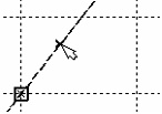
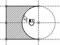
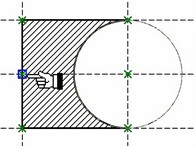
icon in the automenu indicates that the "constrained" drawing mode is active, while the icon ![]() corresponds to the "free" drawing mode. Besides the icons, the mode can be determined by the appearance of the cursor and the nodes being created. If the cursor and the nodes are displayed as crosses, this means, the "constrained" drawing mode is on, while the "box" shape indicates the "free" drawing mode.
corresponds to the "free" drawing mode. Besides the icons, the mode can be determined by the appearance of the cursor and the nodes being created. If the cursor and the nodes are displayed as crosses, this means, the "constrained" drawing mode is on, while the "box" shape indicates the "free" drawing mode.
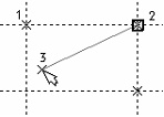
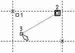
1 - constrained node; 1 - free node;
2 - highlighted constrained node; 2 - highlighted free node;
3 - cursor in the "constrained" drawing mode 3 - cursor in the "free" drawing mode.
Graphic line parameters
The option ![]() calls the graphic line parameters dialog box.
calls the graphic line parameters dialog box.
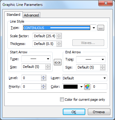
When the dialog of parameters is invoked before creation of a line has begun, it will contain the additional parameter called “Color for the current page only”. This parameter is used only for drawing on pages of the workplanes (see the manual on three-dimensional modeling). When the flag is enabled, the specified color will not be used for all new lines in the document, but only for those lines that are created on the current page of the workplane.
"Standard" Tab
Line Style:
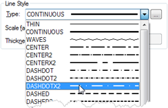
Type. Defines the line type for drawing graphic entities. The line type is selected from the list. The list includes both the standard (included in the system distribution) and the user-defined line types. Standard line types are defined in the file TCAD.LIN. Their description is compatible with that of AutoCAD system. The template files for user-defined types are located in the folder …\Program\LinePatterns.
Scale factor. Defines the Scale factor for dashed line types with respect to the dash size defined in the line type descriptor file (TCAD.LIN). Does not affect display of solid lines. If the scale is notdefined ("Default"), then the scale factor will be taken from the "Scale factor for dashed lines" parameter of the "Lines" tab in the command "ST: Set Document Parameters".
Thickness. Defines the thickness of the graphic entities. If undefined ("Default"), then the thickness for the solid thick line (CONTINUOUS) will be taken from the parameter "Line thickness|Thick lines", while all the rest – from the parameter "Line thickness > Other lines" on the "Lines" tab in the command "ST: Set Document Parameters".
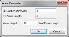
When selecting the "Waves" line type, then, additionally, the [Waves…] button becomes available. This button allows setting waves line parameters: Number of Periods or Period Length of the line, and the line Wave Height. The Wave Height is entered as percentage of the period length. The line start and end parameters:
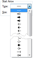
Start and end arrow type (arrow/symbol type). Each graphic line can have its start and end marked by a special symbol. The symbol type is selected from the list.
Start and end arrow size (size of start and end symbols). The sizes of the start and the end symbol are defined independently. Any size can be set at the user's preference. If the symbol size is not defined then the symbol is drawn proportional to the font size defined for the drawing on the "Font" tab in the command "ST: Set Document Parameters".
An additional button ![]() serves to quickly swap the line start and end parameters.
serves to quickly swap the line start and end parameters.
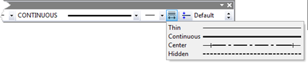
All above parameters are set by default when using one of the standard system line type. The style and ending type are defined for each standard type. A standard line type can be selected from the list coming under the ![]() button.
button.
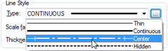
The description of the standard line types is stored in the file SPECLINE.DEF. By default, the file contains the following entries:
Thin THIN 0 0
Continuous CONTINUOUS 0 0
Center CENTER 28 28
Hidden HIDDEN 0 0
The file can be appended by the user as desired. The first parameter is a comment, the second is the line name (this name is used for identifying the line in the line descriptor file), the third and the fourth parameters are the Ids of the start and end symbols (per the enumeration in the endings list).
Color. The graphic line color.
Level. The value of the visibility level of the graphic line.
Priority. The value of the graphic line priority.
Layer. The name of the layer of the graphic line.
Some parameters of graphic lines can be entered in the system toolbar. Especially for graphic lines, the system toolbar provides a button for defining graphic line types, and the graphic line start and end defining buttons.
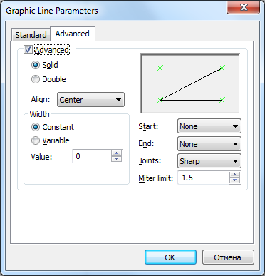
"Advanced" Tab
The "Advanced" tab allows setting the following parameters:
The line display mode:
Solid line. The lines whose "Width" parameter is not 0, will be drawn filled with color.
Double line. The lines whose "Width" parameter is not 0, will be drawn as a contour without filling.
Align. Defines centering of the graphic line with respect to the reference nodes: "Center", "Left", "Right".
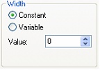
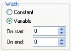
Width. Defines the width of the graphic line: constant or variable. In the case of the constant width, the parameter "Value" defines the line width. If variable width is set then the line width values On start and On end need to be defined.
The "Start" and "End" parameters define the shape of the start and the end of the line, as follows: "None", "Round", "Square".
Joints. This parameter defines the shape of joints of a graphic line created from a 2D path, as follows: "Round", "Sharp", "Mitered".
The size of the rounds and miters depends on the line width setting. If "Round" attribute is set, the segment joints will be rounded with the radius equal to the line half-width. With the "Mitered" setting, the corners at the segment joints are mitered. The distance from the joint node to the miter top is defined by the parameter "Miter limit" as a ratio of the line half-width.

Copying Parameters from Existing Lines
The values of parameters of the graphic line being created can be quickly copied from already existing line. To do so, use the following option:
|
<Alt+P> |
Copy Properties from Existing Element |
This option can be accessed in the automenu of the command before creation of the line or in the process of creation.
After this option is invoked, it is sufficient to specify the graphic line whose values of parameters must be transferred to the line being created.
To assign the copied values of parameters to all new lines, before selection of the original graphic line it is required to enable the additional option:
|
<S> |
Set Properties as Default |
When this option is enabled, all copied parameters will be stored as default parameters.
The given option simplifies creation of the graphic lines having the same parameters. However, it does not allow us to copy individual parameters or parameters from an object of another type. In such cases it is more convenient to use the general mechanism of editing parameters of elements in the window of properties.
Using construction entity selection options
Next, we will describe uses of the listed options in various situations.
Clicking ![]() in the situations described in the headings, accounts for the following actions:
in the situations described in the headings, accounts for the following actions:
1. No nodes neither construction lines are selected
The action ![]() selects the nearest node. Line rubberbanding begins from the highlighted node. This option is sensitive to the drawing mode. In the "constrained" drawing mode, the nearest node is selected, or created in the nearest construction lines intersection (whichever is closer). In the "free" drawing mode the nearest node would be selected only within the zone around the cursor defined by "node join distance". If such node exists then it will be selected. Otherwise, a new "free" node will be created.
selects the nearest node. Line rubberbanding begins from the highlighted node. This option is sensitive to the drawing mode. In the "constrained" drawing mode, the nearest node is selected, or created in the nearest construction lines intersection (whichever is closer). In the "free" drawing mode the nearest node would be selected only within the zone around the cursor defined by "node join distance". If such node exists then it will be selected. Otherwise, a new "free" node will be created.


2. The start node alone is selected
The action ![]() creates a graphic entity – straight line segment from the start node to the node defined by this step. The end node is then highlighted, and new rubberbanding begins from it.
creates a graphic entity – straight line segment from the start node to the node defined by this step. The end node is then highlighted, and new rubberbanding begins from it.


3. A single straight construction line is selected
A node will be selected with the ![]() action, located at the nearest intersection of the highlighted line and some other construction entity (either a line or a circle). The line will stay highlighted, and a new graphic line will begin rubberbanding after the cursor from the highlighted node as the start.
action, located at the nearest intersection of the highlighted line and some other construction entity (either a line or a circle). The line will stay highlighted, and a new graphic line will begin rubberbanding after the cursor from the highlighted node as the start.


4. The start node and a construction entity are selected
The action ![]() creates a graphic line entity – a straight line segment or a curve from the start node to the node defined by this step. The type of the created graphic entity depends on the selection of the underlying construction entity – line, circle, spline, or ellipse. On completing the step, the last selected node stays highlighted, with rubberbanding resuming from there.
creates a graphic line entity – a straight line segment or a curve from the start node to the node defined by this step. The type of the created graphic entity depends on the selection of the underlying construction entity – line, circle, spline, or ellipse. On completing the step, the last selected node stays highlighted, with rubberbanding resuming from there.


The selected node must lie on the selected construction line.
The option ![]() in all the above situations acts in the same way as the action
in all the above situations acts in the same way as the action ![]() . The only difference is, the option <N> can only select existing nodes.
. The only difference is, the option <N> can only select existing nodes.
The option ![]() acts as follows in the described situations:
acts as follows in the described situations:
1. No nodes neither construction lines are selected
The option <L> highlights (selects) the nearest straight construction line. Highlighting the construction line in this case means the start node of the graphic line being created will be constrained to this line. A node will begin rubberbanding, constrained to sliding along the selected line. This indicates that a node can be selected only at an intersection of this line and some other construction entity.


2. The start node alone is selected
The option <L> highlights a straight construction line. The start node stays highlighted, and a new line begins rubberbanding, constrained to stretching along the selected line. This indicates that the end node of the new graphic line can be selected only at an intersection of the highlighted line and some other construction entity.

3. A single construction entity is selected
The option <L> selects the node at the intersection of the already highlighted construction entity and the newly appointed construction line. The selected node becomes the start node for the graphic line being created. The new line begins rubberbanding, constrained to the selected construction entity. If the two selected construction lines do not intersects, no action occurs.


4. The start node and a construction entity are selected
The option <L> selects the node at the intersection of the already highlighted construction entity and the newly appointed construction line. A graphic entity is created from the start node to the newly selected node, which may be a straight line segment or an arc of a circle, depending on the selected (underlying) construction entity. The newly created node and the last selected construction entity stay highlighted, and new line rubberbanding begins along the latter entity.


If the two selected construction lines do not intersect, no action occurs.
The option ![]() is insensitive to the "free" versus "constrained" drawing mode. In either case, its use implies selection of a construction circle entity as the underlying entity for creation of a graphic entity – circle or arc. The option acts as follows in the described situations:
is insensitive to the "free" versus "constrained" drawing mode. In either case, its use implies selection of a construction circle entity as the underlying entity for creation of a graphic entity – circle or arc. The option acts as follows in the described situations:
1. No nodes neither construction lines are selected
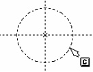
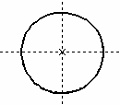
The option <C> creates a graphic entity – circle over the selected underlying construction circle entity.
2. The start node alone is selected
The option <C> selects a construction circle entity. The start node stays highlighted, and an arc starts rubberbanding along the selected circle. An additional option appears in the automenu for flipping the direction of the arc creation:


![]() <Tab> Change arc direction
<Tab> Change arc direction
3. A single construction entity is selected
The effects of using the <C> option in this case are quite similar to the use of the option <L>.
4. The start node and a construction entity are selected (line or circle)
The effects of using the <C> option in this case are quite similar to the use of the option <L>.
The options ![]() and
and ![]() are used similar to the option
are used similar to the option ![]() .
.
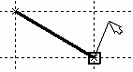
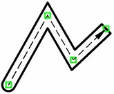
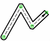
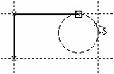
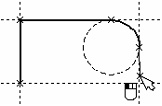
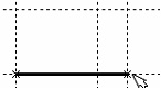
Example of creating a chain of graphic lines
Create a few construction lines. On top of them, draw the graphic lines:
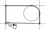
To delete the last created graphic line, one can use the option ![]() .
.
A few tips on creating graphic lines
It is not recommended to use the ![]() action for defining the start node of a graphic entity where there are more than two intersecting construction lines. This is because the node may get created at unintended lines intersection.
action for defining the start node of a graphic entity where there are more than two intersecting construction lines. This is because the node may get created at unintended lines intersection.
In the special case of two or more coinciding nodes, use an appropriate option for selecting construction entities (<L>,<C>,<E>,<S>). First, specify the construction entity to underlie the graphic one, and then either select the node, using the <N> option, or specify the intersecting entity, depending on the situation.
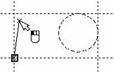
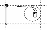
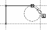
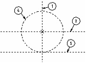
It is a good idea to initially create a node at the intersection of construction lines, using the command "N: Construct Node". In this way, you can precisely specify what lines intersection to use for the node creation. Later, when applying the graphic line, this node can surely be selected using the <N> option. Consider a simple example illustrating the approach. There are several construction lines on the drawing below. Line 1 is constructed vertical, parallel to the Y axis, line 2 is a horizontal, parallel to the X axis, line 3 is constructed parallel to line 2, and, finally, circle 4 is constructed with the center snapped to a node, tangent to line 3. Now, try to apply a graphic arc using the <Enter> option. Note that the created node will not necessarily snap to the intersection of the line and the circle. The node may actually be, for instance, at the intersection of lines 1 and 3. In this case, the circle can't be selected for creating an arc.
A properly built model helps avoid annoying errors. If a node is supposed to be on the intersection of the circle and the line, then it ought to be constructed as such.
Basic rules of graphic line creation
The user is encouraged to follow a few rules when creating graphic line entities:
To avoid errors when creating a parametric drawing, use the option <N> for applying graphic lines. Do not use the <Enter> option if there are more than two construction entities intersecting in one point.
If there is a selected node, then it will be used as the start for a graphic line.
If a node is selected and user attempts to select a construction line entity, it has to be a line passing through the selected node.
If a node and a construction line are selected, and the user selects another construction line, then a graphic line will be created, starting in the selected node and ending at the intersection of the selected lines.
If two construction entities intersect in more than one point (for example, a line and a circle), then the nearest intersection is selected to the graphic cursor location at the time of pressing the option key.
If selecting a construction line entity results in nothing, that means, the lines do not intersect and the graphic line can't be created.
Using grid in "free" drawing mode
If snapping to grid is turned on, then the start and end nodes of the graphic line will be snapping to nearest grid knots. The grid parameters can be defined using the command "Customize|Grid…". The grid can be assigned different steps in the vertical and the horizontal directions, and different shifts with respect to the origin in each direction. When creating a graphic line, the status bar displays the coordinates of the nearest grid knot to the current mouse cursor location. In the "free" drawing mode with grid snapping turned off, a graphic line can be created at an arbitrary location in the drawing area. It does not require constraining to any construction lines.
Editing graphic lines
Editing graphic lines is done by the command "EG: Edit Graphic Line". Call the command via:
Keyboard |
Textual Menu |
Icon |
<EG> |
"Edit|Draw|Graphics" |
|
The following options become available upon calling the command:
![]() <*> Select All Elements
<*> Select All Elements
![]() <R> Select element from list
<R> Select element from list
![]() <Esc> Exit command
<Esc> Exit command
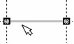
When in the command, one can select a graphic line entity by pointing the cursor and clicking ![]() . Several graphic lines can be simultaneously selected by box. The graphic lines will be selected that are completely within the box.
. Several graphic lines can be simultaneously selected by box. The graphic lines will be selected that are completely within the box.
All graphic lines can be selected at once by typing <*>. To add a graphic line to the set of already selected ones, use the combination <Shift> +![]() . To exclude a graphic line from the selected set, use <Ctrl>+
. To exclude a graphic line from the selected set, use <Ctrl>+![]() .
.
The following options become available after selecting one or several graphic lines:
|
<P> |
Set selected Element(s) Parameters |
|
<Alt+P> |
Copy Properties from Existing Element |
|
<I> |
Select Other Element |
|
<Del> |
Delete selected Element(s) |
|
<Esc> |
Cancel selection |
If only one graphic line is selected, then the following option is available:
|
<O> |
Create Name for selected Element |
If a graphic arc entity is selected, the following additional options become available in the automenu:
|
<Tab> |
Change arc direction |
|
<A> |
Link Arc or Circle to Node |
|
<B> |
Break Link with Node |
If the selected graphic line is created based on a construction line, then Relations for the parent construction line will appear in the 2D window. Those relations are temporary, meaning that those are created by the system automatically upon entering the mode of editing a graphic line, and are automatically deleted upon exiting the mode. Using Relations, you can modify geometrical parameters of the parent construction line in the transparent mode.
Besides that, if the selected graphic line is created based on a construction line, then the second click ![]() after selecting the line (while the cursor is pointing at the line) will invoke the command of editing the original construction line.
after selecting the line (while the cursor is pointing at the line) will invoke the command of editing the original construction line.
To modify parameters of the selected graphic line, use the option ![]() . The initial parameters are taken from the last selected graphic line.
. The initial parameters are taken from the last selected graphic line.
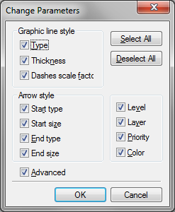
If the user needs to bring the parameters of a graphic line in accord with a given line parameters, then the latter should be selected the last before proceeding with the modifications. This will automatically pre-set the desired parameters in the dialog. If more than one graphic line is selected then another dialog box comes on the screen before the parameters dialog box. Its purpose is to define what parameters of the selected graphic lines are to be modified.
After that, the graphic line parameters dialog box will appear. Now, only the parameters will be modifyable that were specified in the previous dialog box. For instance, if in the previous dialog only the line type was checkmarked for modification, then only this parameter can be modified. Other parameter modifications will be discarded.
Object properties can be also set from another object (including image line) in command waiting mode with the help of the Properties window. See more details in "Main Concepts of System Operation" chapter.
The current set of graphic line parameters defined during the editing can be saved. New graphic line creation would then be based on this particular set of parameters.
To open the parameters dialog box for a single graphic line, one can simply double-click it (![]()
![]() ).
).
The option ![]() is used for assigning a name to the selected graphic line. The name is unique and provides unambiguous identification to the line. The graphic line name can be used instead of its Id number. For example, the function GET() can be used in the variable editor to query a graphic line, named NAME, as follows: GET("NAME", "LENGTH").
is used for assigning a name to the selected graphic line. The name is unique and provides unambiguous identification to the line. The graphic line name can be used instead of its Id number. For example, the function GET() can be used in the variable editor to query a graphic line, named NAME, as follows: GET("NAME", "LENGTH").
The option ![]() allows flipping the direction of graphic arc entity creation.
allows flipping the direction of graphic arc entity creation.
The following options are available in the automenu for graphic arc entities, ![]() and
and ![]() . These options manage a locking node of graphic arcs constructed on top of a construction entity. Throughout modifications of the drawing, the graphic arc will stay over the sector of the underlying construction circle that is closer to the locking node.
. These options manage a locking node of graphic arcs constructed on top of a construction entity. Throughout modifications of the drawing, the graphic arc will stay over the sector of the underlying construction circle that is closer to the locking node.
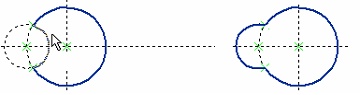
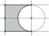
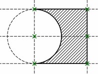
Let's review the following example. When moving one of the original lines, the part is supposed to get mirrored. However, the graphic arc will stay in its original orientation as the vertical line is moved, resulting in the wrong final shape of the part. This can be fixed by using a locking node.

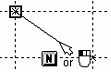
To keep the arc always in the correct sector of the circle, link it to a node. After calling the command "EG: Edit Graphic Line" select the arc and use the option ![]() . The cursor will change to "finger"
. The cursor will change to "finger" ![]() . Then, select the locking node using
. Then, select the locking node using ![]() .
.
Now, as the vertical line is moved, the whole drawing will be flipping, maintaining the original relative configuration.
To release the link with the node, use the option ![]() .
.
To cancel the last graphic line selection and select the next nearest graphic line to the current cursor position, use the option ![]() . This option is convenient when there are several closely located or overlapping graphic lines, and the first selection attempt yielded the wrong graphic line.
. This option is convenient when there are several closely located or overlapping graphic lines, and the first selection attempt yielded the wrong graphic line.
The option ![]() deletes all selected graphic lines. The option
deletes all selected graphic lines. The option ![]() cancels the current selection of graphic lines.
cancels the current selection of graphic lines.
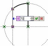
Besides, a capability is provided for reassigning the start and end nodes of the graphic line. Reassigning the nodes is possible for a single selected graphic line. Once the line is selected, the nodes get highlighted. Now, you can move the cursor over one of the highlighted nodes and click it ![]() .
.


The line will then start rubberbanding after the cursor, with another option becoming available:
![]() <N> Select existing Node as the start or end of the graphic line
<N> Select existing Node as the start or end of the graphic line
You can select a node for the graphic line to snap to.
To change parameters of the selected graphic line, it is also convenient to use the system toolbar. With the help of it you can change the color, type, thickness and line ends.
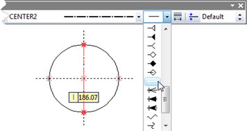
For example, to change the line type with the help of the system toolbar – select the graphic line.
Move the cursor to the line type input box on the system toolbar ![]() and click
and click ![]() . A menu of line types will appear on the screen. Select a new line type by
. A menu of line types will appear on the screen. Select a new line type by ![]() . As the result, the appearance of the graphic line will change.
. As the result, the appearance of the graphic line will change.
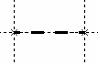
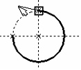
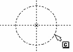
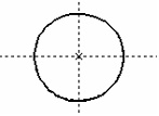
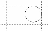
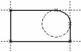
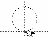
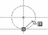
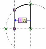
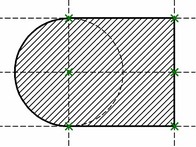
The graphic line endings can also be modified in a similar way. Use of endings is important, for instance, when applying centerlines. These are drawn in a dash-dotted style. To create centerlines with hanging extents, you would not need to create additional nodes beyond the circle (as shown on the diagram). Rather, select the start and end types of the graphic line as shown on the diagram. The size of the extents can be defined explicitly in the parameters of the graphic line, or left as Default. In the latter case, the size will be defined by the parameters in the command "ST: Set Document Parameters", the tab Font, Size parameter.
The same can be done easier. While in the command "G: Create Graphic Line" or "EG: Edit Graphic Line", press the graphic button ![]() on the right-hand side of the system toolbar. The list of the most often used lines with extents will appear.
on the right-hand side of the system toolbar. The list of the most often used lines with extents will appear.