Sketch. Automatic parameterization mode |
  
|
Sketch. Automatic parameterization mode |
|
Creating a non-parametric drawing
T-FLEX CAD allows creating a drawing similar to most well-known CAD systems, using standard functionalities for creating various primitives, such as: line segments, arcs, circles, ellipses, splines. Sketcher functionalities, including object snapping and dynamic tooltips, significantly simplify and speed up the process of creating a non-parametric drawing. Such drawings do not share the advantage of parametric drawings in the effective usage of modifiable parameters (dimensions). However, in certain cases, development of such drawings is faster and can bring certain benefits, when large modifications are not expected.
Quick creation of graphic lines in a drawing is done with the "Sketch" command. This command can work in two modes: in the sketching mode and in the automatic parameterization mode.
Creating Lines in a Drawing
To quickly create graphic lines use the command "SK: Create Sketch":
Icon |
Ribbon |
|---|---|
|
Draw → Sketch |
Keyboard |
Textual Menu |
<SK> |
Construct > Sketch |
Upon calling the command, the options appear in the automenu that allow creating various lines in a drawing. You can use all object snaps available in the system to make your constructions.
Two working modes of the command "SK: Create Sketch"
The "SK: Create Sketch" command can work in one of the two modes: in the sketching mode and in the automatic parameterization mode. Switching between the modes is done with the icon ![]() on the “View” panel. When the icon is switched off, a plain sketch is created. When the icon is On, the automatic parameterization mode is at work.
on the “View” panel. When the icon is switched off, a plain sketch is created. When the icon is On, the automatic parameterization mode is at work.
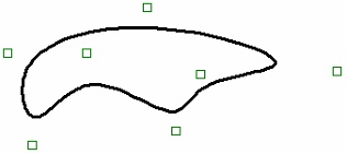
In the sketching mode, only the graphic lines based on free nodes are created. To create graphic lines, the user selects the desired type (a line segment, an arc, circle, etc.) and defines the position of the line defining points using ![]() or by entering coordinates/parameters in the command's properties window. When specifying the positions of the defining points of the lines being created, one can use object snaps to existing drawing elements (a vertical/horizontal relation, tangency, perpendicularity, etc.). As a result, you get a nonparametric drawing without construction lines (a "sketch").
or by entering coordinates/parameters in the command's properties window. When specifying the positions of the defining points of the lines being created, one can use object snaps to existing drawing elements (a vertical/horizontal relation, tangency, perpendicularity, etc.). As a result, you get a nonparametric drawing without construction lines (a "sketch").
In the automatic parameterization mode the user also builds up a drawing as a sketch, using all available command tools. Instead of the free nodes, the system automatically creates construction elements beneath the graphic lines, that are tied by parametric relations.
The types of relations introduced by the system depend on:
●the options of the command that was used to create a graphic line;
●the object snaps used when creating the line;
●parameters defined in the command's properties window.
As a result, a fully functional parametric drawings is built. At the same time, you need to note that the system automatically defines the types of parametric dependences created between elements, which may not always meet the user's preferences.
Details on working in the automatic parameterization mode are provided at the end of this chapter, in the section "Working in the Automatic Parameterization Mode".
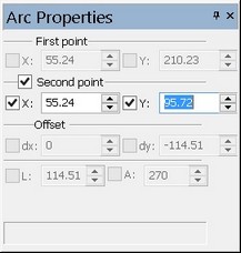
Using property window
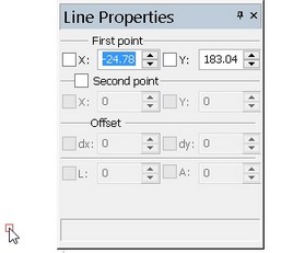
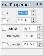
When sketching lines, the point coordinates can be simply defined by clicking ![]() in the drawing area. To enter exact node coordinates, the property window is used in this command. It allows defining absolute, relative, or polar coordinates of the elements being created and their parameters.
in the drawing area. To enter exact node coordinates, the property window is used in this command. It allows defining absolute, relative, or polar coordinates of the elements being created and their parameters.
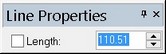
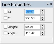
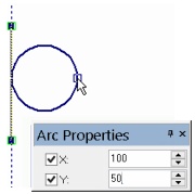
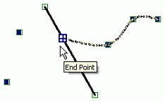
When the pointer is in the drawing area, the property window tracks the current coordinates of the pointer. If necessary, those can be changed in transparent mode by typing the desired value directly from the keyboard. The active input box can be set by pointing and clicking ![]() , or from the keyboard. The key combinations for switching to one or another input box are displayed in the ToolTips as the pointer is rested over the desired field. When entering a value in the property window, a flag before the input box is automatically set that blocks modifications of the value via the pointer in the drawing area.
, or from the keyboard. The key combinations for switching to one or another input box are displayed in the ToolTips as the pointer is rested over the desired field. When entering a value in the property window, a flag before the input box is automatically set that blocks modifications of the value via the pointer in the drawing area.
To complete the point creation, simply press [Enter] or ![]() in the drawing area after entering the coordinates.
in the drawing area after entering the coordinates.
Either Cartesian or polar coordinates can be used for creating elements, separately or in combination. That helps creating various configurations of points in the most convenient way for the moment.
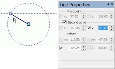
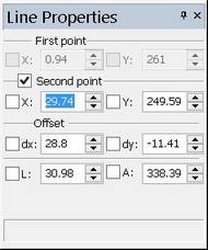
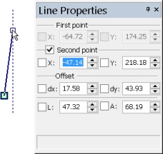
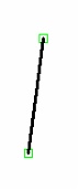
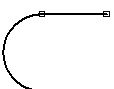
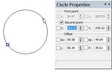
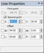
For example, when specifying the second point of the segment, one can enter the value of the distance and the length of the vector. Auxiliary elements will be displayed in the drawing: a circle with the center at the segment start, of the radius equal to the specified distance, and a horizontal line offset from the segment start at the distance equal to the Y shift ("dy"). The intersection points of the circle and the line define the possible configurations for the second point of the segment under the specified parameters.
As the pointer moves around the drawing, this point will appear as a free node jumping from one intersection point to the other and back. Selecting the desired point and clicking ![]() completes the segment creation.
completes the segment creation.
Continuous line input
Continuous input of sketch elements is supported by the automenu option:
![]() <J> Continuous creation
<J> Continuous creation
In this case, the end point of the last created element (segment, arc) becomes the start point of the next one.
This mode does not affect closed elements (circle, rectangle, polygon, ellipse, closed spline).
Using offset from node
When creating sketch elements, the position of any point of the elements being created can be defined relative to another point. To do this, use the automenu option
![]() <Z> Offset
<Z> Offset
This option can be called in transparent mode at any stage of creating sketch elements. Upon selecting the option, select the point to offset from. Then, the offset distance is defined in relative or polar coordinates, using the pointer and/or the property window. The system then returns to element creation.
Creating line segments
Any time the command is called, the system is ready for inputting line segments, as indicated by the pushed icon in the automenu:
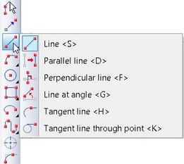
![]() <S> Line
<S> Line
A black triangle in the lower right corner of the icon indicates presence of a pull-down list of options. Holding the button ![]() depressed over the icon a bit longer opens the menu with more options.
depressed over the icon a bit longer opens the menu with more options.
To create a simple line segment (the option ![]() ), one needs to define two points. The points can be specified arbitrarily by pointing in the drawing area and clicking
), one needs to define two points. The points can be specified arbitrarily by pointing in the drawing area and clicking ![]() or by entering the exact coordinates (offsets) in the property window. One can specify point coordinates relative to the selected point or node in the drawing using the option <Z> (
or by entering the exact coordinates (offsets) in the property window. One can specify point coordinates relative to the selected point or node in the drawing using the option <Z> (![]() ).
).
When creating a line, existing nodes can be selected as the line ends.
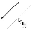
Parallel line
To create a parallel line, select the option:
![]() <D> Parallel line
<D> Parallel line
In this case, select a line by the mouse, to be used as the reference for constructing a parallel line. A line will start rubberbanding on the screen parallel to the selected line. If the continuous input mode is used, then this line will be parallel to the last input segment. To cancel a segment selection, right click ![]() .
.
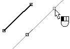
After selecting the reference line segment, specify the distance to the segment being created, the start point and the length of new segment. This can be done freely by moving the pointer and clicking ![]() at the desired positions in the drawing, or input exactly in the property window.
at the desired positions in the drawing, or input exactly in the property window.
The property window allows entering coordinates of the start point of the parallel line. This also defines the distance between the lines. A node will be created in the specified point. From now on, the rubberbanded line will pass through this node.
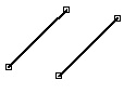
The line end can be input arbitrarily by moving the pointer along the line and clicking ![]() , or by exact value in the properties window, entering either line length or second point coordinates.
, or by exact value in the properties window, entering either line length or second point coordinates.
The distance between the lines can also be entered in the property window. In this case, the rubberbanded line will be fixed at the specified distance from the original line segment. A node will rubberband along the line, following the cursor, defining the start of the new segment. Its position is defined by clicking ![]() . After that it is necessary to set the line length or its second point coordinates.
. After that it is necessary to set the line length or its second point coordinates.

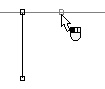
Perpendicular line segment
A perpendicular line segment can be created using the option:
![]() <F> Perpendicular line
<F> Perpendicular line
In the continuous input mode, upon this option selection, an infinite line will be displayed that is perpendicular to the last input line segment and passing through its end node. The latter node will be used as the start of the segment being created. In this case, use the mouse pointer for fixing the rubberbanded node position by clicking ![]() or entering a value in the property window.
or entering a value in the property window.
To create a line perpendicular to another segment or to the same segment that is not passing through the end node, the current system selection can be rejected by right clicking ![]() while in the continuous input mode. One right click
while in the continuous input mode. One right click ![]() cancels the selection of the start point of the segment being created. The second right click
cancels the selection of the start point of the segment being created. The second right click ![]() cancels the selection of the reference segment, allowing manual selection of the desired segment. The further construction steps in this case are similar to creation of a parallel line.
cancels the selection of the reference segment, allowing manual selection of the desired segment. The further construction steps in this case are similar to creation of a parallel line.
Slanted line
To create a line segment at the specified angle to another segment, use the automenu option:
![]() <G> Line at angle
<G> Line at angle
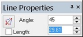
This kind of line is constructed similar to the perpendicular type, except that the angle can be entered in the property window. The icon ![]() in the property window helps quickly change the specified angle for the complementary one based on 1800.
in the property window helps quickly change the specified angle for the complementary one based on 1800.
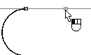
Line tangent to an arc and passing through arc end
This configuration is supported by the automenu option:
![]() <H> Tangent line
<H> Tangent line
First, select the tangency arc. An auxiliary line will be displayed in the screen, tangent to this arc. The line will be snapped to the end of the arc nearest to the pointer at the time of arc selection. Move the pointer with the rubberbanded node along the line and fix the second node position by clicking ![]() or by input into property window.
or by input into property window.


Line tangent to a circle or arc
![]() <К> Tangent line through point
<К> Tangent line through point
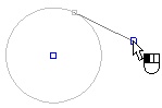
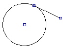
With this option, select a circle or arc (other elements are disallowed from selection), to which the tangency line is to be constructed. The selected element will be highlighted, and the arc will be extended by an auxiliary circle. An auxiliary node will be rubberbanding along the circle. This will be the first node of the line segment, defining the tangency point between the line and the circle. The line will be rubberbanding between the node and the pointer. To complete the tangent line, fix the position of the second node outside the circle.
The position of the second node can be defined arbitrarily by clicking ![]() (use object snapping as appropriate), or select an existing node. Besides, one can use the property window by specifying coordinates of the node or the length of the line or else the angle to the horizontal of the radius pointing to the tangency point between the line and arc. The position of the first line node will be defined automatically.
(use object snapping as appropriate), or select an existing node. Besides, one can use the property window by specifying coordinates of the node or the length of the line or else the angle to the horizontal of the radius pointing to the tangency point between the line and arc. The position of the first line node will be defined automatically.

Constructing arcs
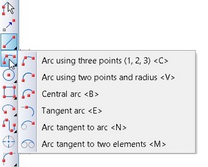
As is the case of line segments, the set of icons for creating various types of arcs is in the pull down menu. Any of the enclosed icons can be displayed at the top level of the automenu when sketching. Usually, it is the icon corresponding to the last used option in this command.
Arc by three points
![]() <C> Arc by three points
<C> Arc by three points
This option defines the mode of creating an arc by three points. The first and third points are the end points of the arc. The second point defines the arc position.
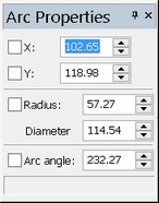
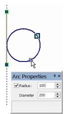
The arc can be arbitrarily input by selecting three points with the mouse, or specified exactly in the property window. In the latter case, the second point is defined in absolute coordinates or by the offsets with respect to the first point of the arc. To define the third point, one can use absolute coordinates, the radius, the diameter or the angular length of the arc in various combinations.
The coordinates of any point of the arc can be specified by offsets with respect to a selected point or node in the drawing with the option <Z> (![]() ).
).


Arc by two points and radius
To create and arc by two nodes, turn on the automenu option:
![]() <V> Arc by two points and radius
<V> Arc by two points and radius
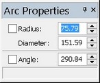
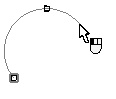
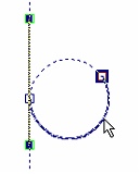
Use the mouse or the property window to define the two end points of the arc being created. After that, the arc will start rubberbanding on the screen following the pointer. To fix the arc, move the pointer to the desired position and click ![]() , or enter the value of the angle or the arc radius (diameter) into the property window.
, or enter the value of the angle or the arc radius (diameter) into the property window.


Arc by center and ends
Creation of an arc with the specified center is done in the mode provided by the option:
![]() <B> Central arc
<B> Central arc
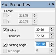
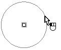
To construct a central arc, specify the center and radius (diameter), as well as the start and end angles of the arc. This can be done freely by using ![]() , or exactly in the property window. After defining the center, a circle starts rubberbanding on the screen. The input boxes become accessible in the property window for entering the radius (diameter) and the start angle of the arc. Those can be defined by moving the pointer to the desired position and clicking
, or exactly in the property window. After defining the center, a circle starts rubberbanding on the screen. The input boxes become accessible in the property window for entering the radius (diameter) and the start angle of the arc. Those can be defined by moving the pointer to the desired position and clicking ![]() . Next, move the pointer along the fixed circle in the desired direction of the arc, and once more click
. Next, move the pointer along the fixed circle in the desired direction of the arc, and once more click ![]() .
.
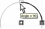
To quickly flip the arc direction, one can use the <Tab> key. Besides, the arc angle can be defined in the property window after fixing the input radius and the start angle of the arc with the [Enter] key or clicking ![]() in the drawing area.
in the drawing area.


At the third step of the arc construction, the system offers snappings to typical angles of the arc.
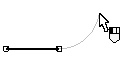
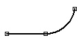
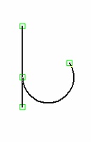
Tangent arc
To create an arc, tangent to a graphic entity (an arc or a line segment), start the respective mode with the icon:
![]() <E> Tangent arc
<E> Tangent arc
After that, select a graphic line. The arc will originate in the end node of the selected line nearest to the pointer position at the time of selection. In the continuous input mode, the arc originates in the end node of the last created element. The rubberbanding arc can be moved by the mouse to the desired position and fixed. The position of such arc can be specified in exact values. To do this, select a graphic line, and then specify the end point coordinates of the arc in the property window. Alternatively, one can specify the radius (diameter) and the arc angle. In the latter case, first use the mouse to specify the direction of the arc.

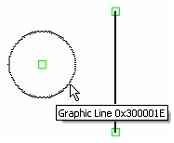
Arc tangent to another arc
![]() <N> Arc Tangent To Arc
<N> Arc Tangent To Arc
This automenu option allows selecting an entity (a line segment, circle or arc), to which the arc being created should be made tangent. The selected element will be highlighted and projected (extended) up to the full line or circle. A rubberbanding circle will appear on the screen, tangent to the selected element. The position and the size of the circle change as the pointer moves.
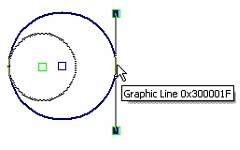
The second step is constructing the end node away from the tangency entity, for the arc being created to pass through. This node can be freely defined by placing the pointer at the desired position, by watching the coordinates displayed in the status bar ![]() , or by defining the offsets from another node or point (the option <Z>) or by entering exact coordinates in the property window. As a result, the rubberbanding circle will pass through the specified node, while staying tangent to the entity defined by the step one.
, or by defining the offsets from another node or point (the option <Z>) or by entering exact coordinates in the property window. As a result, the rubberbanding circle will pass through the specified node, while staying tangent to the entity defined by the step one.
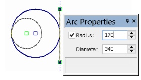
Next, specify the radius (diameter) of this auxiliary circle, either by entering a specific value in the property window, or freely by clicking ![]() . As a result, the position of the auxiliary circle will be fixed. A node will be created at the tangency point between the circle and the selected entity. What is left is defining the direction of the arc on the auxiliary circle between the two nodes. To do this, simply point with the mouse at the desired position.
. As a result, the position of the auxiliary circle will be fixed. A node will be created at the tangency point between the circle and the selected entity. What is left is defining the direction of the arc on the auxiliary circle between the two nodes. To do this, simply point with the mouse at the desired position.
The rubberbanding arc will be flipping following the pointer. After selecting the desired position, click ![]() , and the arc will be fixed.
, and the arc will be fixed.
 or
or 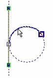
Arc tangent to two entities
![]() <M> Arc Tangent to Two Elements
<M> Arc Tangent to Two Elements
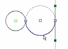
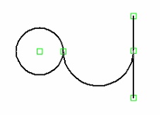
This automenu option allows creating an arc tangent to two entities simultaneously (circles, arcs or line segments). The arc construction begins with subsequent selection of two reference entities defining the tangency with the arc. As in the previous case, the selected elements are highlighted. A circle will start rubberbanding on the screen, tangent to the selected entities. The position and the size of the circle change as the pointer moves. The circle position and size can be modified using the <Spacebar> key.
Next, define the radius (diameter) of the auxiliary circle, by either entering a specific value in the property window or by clicking ![]() . As a result, the position of the auxiliary circle will be fixed. The nodes will be created at the tangency points between the circle and the entities.
. As a result, the position of the auxiliary circle will be fixed. The nodes will be created at the tangency points between the circle and the entities.
What is left is to define the position of the arc itself in the auxiliary circle between the two nodes. To do this, simply move the pointer to the desired position - the rubberbanding arc will be flipping with the pointer. Select the desired position and click ![]() . This will fix the arc.
. This will fix the arc.
 or
or 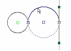
Creating a circle
This option, just like previous ones, contains a pull-down list of options for constructing various types of circles.
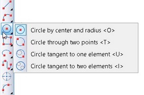
Circle by center and radius
This type of circle can be created using the automenu option:
![]() <O> Circle By Center And Radius
<O> Circle By Center And Radius
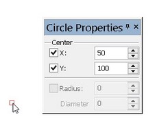
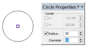
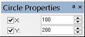
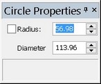
To create a circle, specify the position of the center and the radius (diameter). This can be done freely by the mouse ![]() , or, alternatively, by entering the exact values of the center coordinates and the radius (diameter) in the property window.
, or, alternatively, by entering the exact values of the center coordinates and the radius (diameter) in the property window.
Circle through two points
![]() <T> Circle through two points
<T> Circle through two points
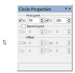
This option is intended for creating a circle passing through two points. The two points for the circle to pass through can be defined by clicking ![]() or by entering coordinates in the property window. Next, define the radius (diameter) of the circle. To do this, specify the third point with the mouse
or by entering coordinates in the property window. Next, define the radius (diameter) of the circle. To do this, specify the third point with the mouse ![]() , defining the position and the radius of the circle, or, again, resort to the property window.
, defining the position and the radius of the circle, or, again, resort to the property window.

Circle tangent to one entity
To create a circle tangent to one entity (an arc, circle or line segment), use the automenu option:
![]() <U> Circle Tangent To One Element
<U> Circle Tangent To One Element
The circle construction begins with selecting the element to which the circle will be tangent. The selected entity will be highlighted, and a circle will start rubberbanding on the screen, tangent to the selected entity. The position and the size of the circle change as the pointer moves. Meanwhile, the property window allows entering the exact coordinates of a point away from the tangency entity defining the circle being created. The position office point can also be specified by clicking ![]() , or using the option <Z>. Next, define the radius (diameter) of the circle by clicking
, or using the option <Z>. Next, define the radius (diameter) of the circle by clicking ![]() or in the property window.
or in the property window.
Circle tangent to two entities
To create a circle tangent to two entities, use the option:
![]() <I> Circle Tangent To Two Elements
<I> Circle Tangent To Two Elements
The first step of creating the circle is subsequent selection of two tangency entities. The selected elements are highlighted, and a circle starts rubberbanding on the screen, tangent to those entities. The position and the size of the circle change as the pointer moves. The position and the size of the circle can be changed using the <Spacebar> Key. The position and the radius of the circle can be fixed by clicking ![]() at a point away from the tangency entities or via the property window.
at a point away from the tangency entities or via the property window.
Creating polygons
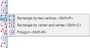
This option also contains a pull down list of icons that allow creating a common rectangle, as well as an arbitrary equilateral polygon.
The created polygons are combinations of separate segments. Each segment can be edited as a separate entity.
Creating rectangle by Two Vertices
To create a rectangle, use the option:
![]() <Shift+P> Rectangle by two vertices
<Shift+P> Rectangle by two vertices
To construct a rectangle it is sufficient to specify the location of its two opposite corners. The points can be defined arbitrarily either with the help of ![]() or by specifying precise coordinates in the properties window.
or by specifying precise coordinates in the properties window.
Creating rectangle by center and vertex
To construct a rectangle by center and vertex we use the option:
|
<Shift+С> |
Rectangle by center and vertex |
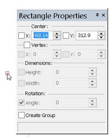
Construction of a rectangle starts with indication of a central point. Location of the point can be specified directly in the drawing’s window with the help of ![]() or by specifying precise coordinates in the properties window.
or by specifying precise coordinates in the properties window.
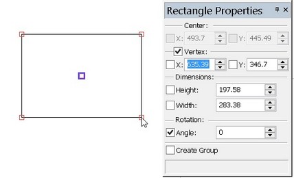
Then it is required to specify location of the remaining vertices of the rectangle. This can be done by simply indicating location of one of the vertices of the rectangle on the drawing with the help of ![]() . It is also possible to specify in the properties window the precise values of the height and width of the rectangle, but in this case to complete element’s creation it is required, after parameters specification, to execute “confirmation” by pressing
. It is also possible to specify in the properties window the precise values of the height and width of the rectangle, but in this case to complete element’s creation it is required, after parameters specification, to execute “confirmation” by pressing ![]() in the drawing’s window.
in the drawing’s window.
It is also possible to combine these two methods: to enter, for example, only the height in the properties window, and define the width by indicating the point on the drawing.
or

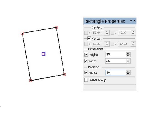
Before completion of rectangle’s creation – i.e., before indication of the coordinates of the second point (vertex), or the values of the height and width of the rectangle – it is also possible to additionally indicate the rotation angle.
It is possible to define the rotation angle for the rectangle by precise value in the properties window (the “Angle” parameter) or directly on the drawing. By default the “Angle” parameter in the properties window is checked, i.e. the rotation angle is specified only as a numeric value. To specify it in the drawing’s window it is required to uncheck it. After that it is possible to specify the rotation angle in the drawing’s window.
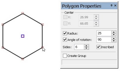
Creating equilateral polygon
To create an equilateral polygon, use the option:
![]() <Shift+R> Polygon
<Shift+R> Polygon
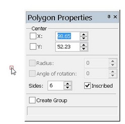
To first step in creating a polygon is defining its center. The point position can be defined either by clicking ![]() or by entering the exact coordinates in the property window. In the same window, one can specify the number of sides and the type of the polygon (inscribed or circumscribed). Next, define the radius and the rotation angle of the polygon. To do this, either define a point by clicking
or by entering the exact coordinates in the property window. In the same window, one can specify the number of sides and the type of the polygon (inscribed or circumscribed). Next, define the radius and the rotation angle of the polygon. To do this, either define a point by clicking ![]() , to become a polygon vertex, if inscribed, or a midpoint of a side, if circumscribed, or else explicitly enter the radius and the polygon rotation angle in the property window.
, to become a polygon vertex, if inscribed, or a midpoint of a side, if circumscribed, or else explicitly enter the radius and the polygon rotation angle in the property window.
 or
or 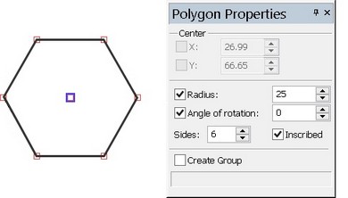
Creating ellipses and elliptical arcs
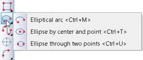
This option, just like previous ones, has a pull down list of icons for creating an ellipse or elliptical arc.
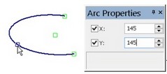
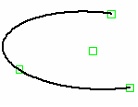
Elliptical arc
To create an elliptical arc, use the option
![]() <Ctrl+M> Graphic Elliptical Arc
<Ctrl+M> Graphic Elliptical Arc
After calling the option, define four points: the center of the ellipse, the start point of the arc, the end point of the arc and an additional point in the elliptical arc defining its position. The point positions can be freely defined by clicking ![]() , or entered exactly in the property window.
, or entered exactly in the property window.
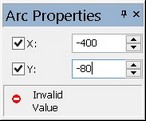
After defining the center and endpoints, an elliptical arc will start rubberbanding on the screen following the pointer. The pointer defines position of the additional point in the arc. If the rubberbanding arc disappears, that means, the arc cannot be created at this pointer position. The point coordinates can also be entered in the property window. In a special pane provided in the window, a relevant warning message is displayed upon an attempt to enter inadmissible point coordinates.
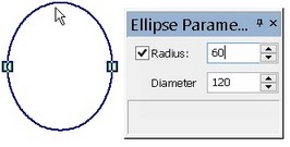
Ellipse by center and point
![]() <Ctrl+T> Ellipse by center and point
<Ctrl+T> Ellipse by center and point
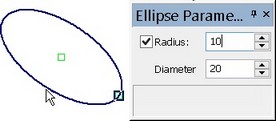
This option allows creating an ellipse by subsequently defining its center, a point defining the length of one ellipse semi axis, and the length of the second semi axis (the radius). As for other sketch entities, the point positions can be specified by simply clicking ![]() within the drawing area or by exact values in the property window.
within the drawing area or by exact values in the property window.
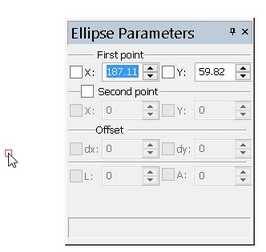
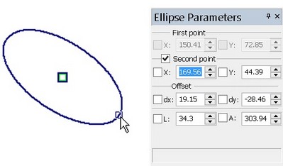
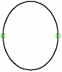
Ellipse through two points
![]() <Ctrl+U> Ellipse through two points
<Ctrl+U> Ellipse through two points
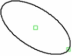
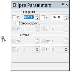
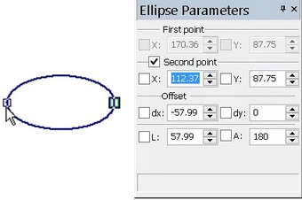
The option allows creating an ellipse by specifying subsequently two points as the ends of one of its semi axes and then defining the length (the diameter) or half length (the radius) of the second axis.
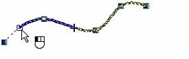
Constructing splines
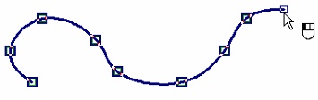
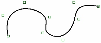
The following group of options provides for constructing splines of two main types: those directly passing through the defining nodes, and those using the nodes as vertices of the control polygon. Either type splines can be either closed or open. Creating sketch splines is mostly similar to creating construction spline entities.
After defining the first node of any spline, the following options become available in the automenu:
|
<Ctrl+Enter> |
Finish Spline input |
|
<P> |
Set graphic line parameters |
|
<Z> |
Offset |
|
<T> |
Set direction at Spline start/end |
|
<Esc> |
Cancel selection |
When defining spline nodes, the curve being created will be rubberbanding with the pointer. When creating a spline by control polygon, the control polygon will also rubberband. To complete spline creation, use the options ![]() ,
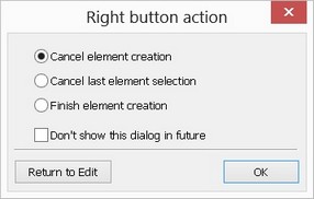
, ![]() . One can also right click
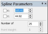
. One can also right click ![]() in the drawing area and select the desired action: cancel spline creation, reject selection of the last spline node, finish spline input. When creating a spline, the property window can be used to define the absolute coordinates over current node being created, the number of spline segments and the weights (for splines by control polygon).
in the drawing area and select the desired action: cancel spline creation, reject selection of the last spline node, finish spline input. When creating a spline, the property window can be used to define the absolute coordinates over current node being created, the number of spline segments and the weights (for splines by control polygon).
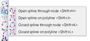
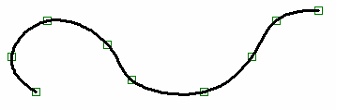
Open splines through nodes
An open spline passing through nodes is constructed using the option:
![]() <Shift+H> Open spline through node
<Shift+H> Open spline through node
When creating this kind of spline, one can additionally specify end point conditions by using tangency vectors. The vector directions are defined by specifying an additional node using the options ![]() /
/![]() . If called right after specifying the first spline node, the option creates the tangency vector for the spline start. Calling the option in the situation, when more than one spline node has been already defined, creates the tangency vector for the end of spline. In this case, the last defined node of the spline is considered its end, and spline creation completes automatically at this point.
. If called right after specifying the first spline node, the option creates the tangency vector for the spline start. Calling the option in the situation, when more than one spline node has been already defined, creates the tangency vector for the end of spline. In this case, the last defined node of the spline is considered its end, and spline creation completes automatically at this point.
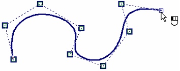
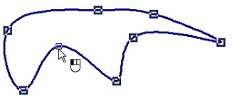
Open spline by control polygon
An open spline by control polygon is constructed using the option:
![]() <Shift+J> Open spline on polyline
<Shift+J> Open spline on polyline
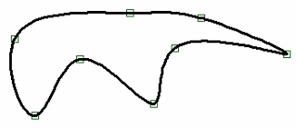
Closed spline through nodes
A closed spline passing through nodes is constructed using the option:
![]() <Shift+K> Closed spline through node
<Shift+K> Closed spline through node
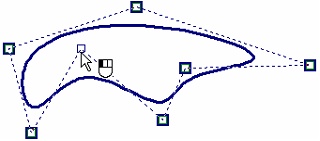
Closed spline by control polygon
A closed spline by control polygon is constructed using the option:
![]() <Shift+L> Closed spline on polyline
<Shift+L> Closed spline on polyline
Creating fillets and chamfers
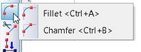
The options for constructing chamfers and various kinds of fillets between two existing entities are also united in one pull down menu.
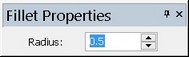
![]() <Ctrl+A> Fillet
<Ctrl+A> Fillet
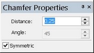
![]() <Ctrl+B> Chamfer
<Ctrl+B> Chamfer
When constructing chamfers and fillets, the existing graphic lines are modified, and new ones are created. Constructing chamfers and fillets itself is done by simply selecting two intersecting segments, or the segments whose extensions intersect. Meanwhile, the property window allows defining the width for symmetrical chamfers, or the angle for asymmetrical ones, or the fillet radius.
Center lines
To create center lines for such entities as arcs, circles and ellipses, enter the appropriate mode by calling the automenu option:
![]() <Ctrl+Q> Axis lines
<Ctrl+Q> Axis lines
After the, simply select any circle, arc or fillet, and center lines will be created automatically.
 or
or 

Creating offsets
![]() <Ctrl+J> Offset of a group of Graphic Lines
<Ctrl+J> Offset of a group of Graphic Lines
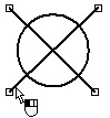
This option is provided for creating offsets to a group of connected graphic entities. The group of entities can include line segments and arcs connected into a continuous sequence.
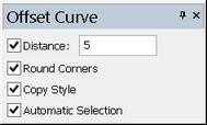
The offset type is defined in the property window. The flag "Automatic selection" sets the mode of automatic search for line sequences. In this mode, simply select by clicking ![]() at least one line in a continuous sequence, and all the rest will be found automatically. Should forks be encountered, the automatic search stops. It will resume only after specifying the continuation for the search. If the automatic search mode is off, each line needs to be selected manually.
at least one line in a continuous sequence, and all the rest will be found automatically. Should forks be encountered, the automatic search stops. It will resume only after specifying the continuation for the search. If the automatic search mode is off, each line needs to be selected manually.
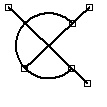
Setting the flag "Round corners" causes automatic filleting of the chain being created. The flag "Copy style" allows transmitting the original line properties onto the offset lines (the type, width, color, etc.).
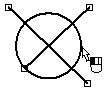
In the process of offset creation, the offset being created will be rubberbanding following the pointer. The offset position can be defined freely by clicking ![]() or exactly by entering the offset value in the property window.
or exactly by entering the offset value in the property window.
Manipulations with line segments
Existing line segments can be modified using the option
![]() <Shift+I> Trim Graphic Line
<Shift+I> Trim Graphic Line
To trim off a piece of a line segment or any other sketch entity, use the mouse and select the piece to trim off. If a free end of a segment was selected, it will be cut off by the nearest intersecting line. If the selected portion of a segment or arc is between two intersections, then the selected entity will be cut at those intersections.
The following option allows modifying any sketch entities except a full circle:
![]() <Ctrl+I> Extend graphic line
<Ctrl+I> Extend graphic line
In this case, the selected entity will be extended or shortened. The position of the pointer at selection time is important. The selected element and its extension will be highlighted. If a line segment was selected, then the infinite line extension will be highlighted. If it was an arc, then the extension circle will be highlighted. The end node nearest to the pointer at the time of selection will also be highlighted. This node can be moved by the mouse to either side. The node position and, hence, the new image of the entity can be fixed by clicking ![]() . Alternatively, you can select a graphic line to which the current entity needs to be extended or shortened.
. Alternatively, you can select a graphic line to which the current entity needs to be extended or shortened.
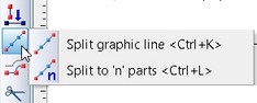
To divide existing graphic lines into several pieces, use the options in the respective pull down menu.
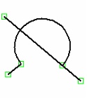
To divide an existing graphic entity into two at the specified point, use the option:
![]() <Ctrl+K> Split graphic line
<Ctrl+K> Split graphic line
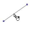
To do this, select any graphic entity created by the command "SK: Create Sketch" or "G: Create Graphic Line". The selected entity will be highlighted, with a node rubberbanding along the entity, dividing the entity into two. Clicking ![]() fixes the node position. The node can also be specified as an intersection point of the selected entity with another graphic entity (a line segment, circle or arc). To do this, selecte a graphic line, whose intersection with the current entity will be the dividing point of the current entity.
fixes the node position. The node can also be specified as an intersection point of the selected entity with another graphic entity (a line segment, circle or arc). To do this, selecte a graphic line, whose intersection with the current entity will be the dividing point of the current entity.
As a result, a node will be created at the specified position, dividing the original entity into two.
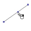
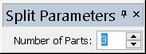
To divide an entity into an arbitrary number of equal parts, use the automenu option
![]() <Ctrl+L> Split to "n" parts
<Ctrl+L> Split to "n" parts
Upon calling the option, specify an entity to divide. If a closed entity was selected (a circle, ellipse or a closed spline), additionally specify the start point of division. As a result, the selected entity will be divided into the specified number of equal parts. The nodes will be created at the division points. The number of division parts of the entity is specified in the property window.
Modifying splines
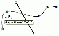
Spline modifications are done somewhat different then other sketch entities. Let's review an example of trimming spline using the option ![]() . Upon calling the option, pick on the spline near one of its ends hanging off the intersection with another graphic entity - a line segment. As a result, the spline will be trimmed up to the intersection point. However, the geometrical characteristics of the spline are not modified by the section. The spline keeps the same set of defining nodes, it is only the visible image that has been trimmed. Instead of a node (that would disturb the spline geometry), a special section point is created at the intersection, called a "graphic line intersection". This point becomes visible only when the spline is selected.
. Upon calling the option, pick on the spline near one of its ends hanging off the intersection with another graphic entity - a line segment. As a result, the spline will be trimmed up to the intersection point. However, the geometrical characteristics of the spline are not modified by the section. The spline keeps the same set of defining nodes, it is only the visible image that has been trimmed. Instead of a node (that would disturb the spline geometry), a special section point is created at the intersection, called a "graphic line intersection". This point becomes visible only when the spline is selected.
Shortening a spline (the option ![]() ) is done in the same way as the trimming – the spline geometry is not modified, however, an intersection point is created in the specified position, limiting the spline visible image.
) is done in the same way as the trimming – the spline geometry is not modified, however, an intersection point is created in the specified position, limiting the spline visible image.
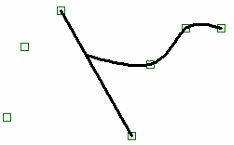
When dividing spline into parts (the options ![]() and
and ![]() ), the new geometrically coinciding splines are created, based on the same nodes as the original spline. The number of created splines will correspond to the number of divisions. The visible image of each spline will be limited by the trimming points according to the bounds of the respective parts of the original spline. In this case, the spline may have two trimming points limiting its image.
), the new geometrically coinciding splines are created, based on the same nodes as the original spline. The number of created splines will correspond to the number of divisions. The visible image of each spline will be limited by the trimming points according to the bounds of the respective parts of the original spline. In this case, the spline may have two trimming points limiting its image.
The position or the trimming point of a spline can be modified when editing the spline (see the section "Editing sketch").
Graphic line parameters
Parameters of a graphic entity can be defined or modified at any moment of sketch creation or editing. The dialog box defining the parameters is called by the option:
![]() <P> Set graphic line parameters
<P> Set graphic line parameters
Detailed description of graphic entity parameters can be found in the chapter "Graphic lines".
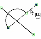
Working in the Automatic Parameterization Mode
Let's review in detail working in the auto-parameterization mode. The general rules of creating lines in the drawing are the same here as in the sketching mode. Those fully correspond to what was said in the previous sections of this chapter. What is different is the result of construction – construction lines and based on them constrained nodes are automatically created instead of free nodes.
The constructions created by the system in the auto-parameterization mode depend on the type of the line being created, the object snaps used in its creation and the line parameters defined in the command's properties window. Let's review working in the auto-parameterization mode using several simple examples.
Let's start with constructing a simple segment. To construct such a segment, we need to specify the positions of its two nodes. In the sketching mode, the system will create two free nodes in the specified points, and a graphic line between them. In the auto-parameterization mode, the created nodes will be constrained. The method of constructing constrained nodes may vary.
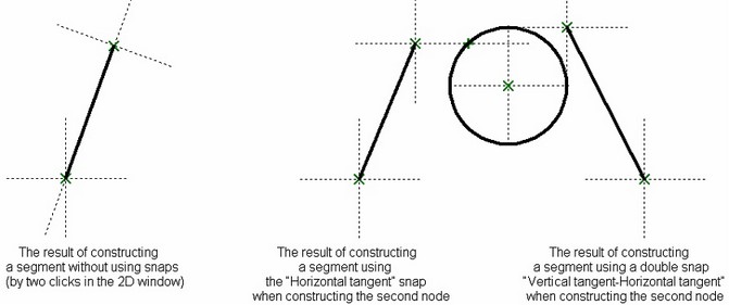
For example, if no snaps are used for creating the nodes of such a segment and you do not enter parameters in the properties window, then the segment nodes are constructed as follows:
- For the first node, a vertical and a horizontal line are created at the specified point, whose intersection will be the node position;
- For the second node, two lines are created as well. The first is constructed as going through the first segment node at an angle to the horizontal. The second is constructed perpendicular to the first line at a distance from the first segment node.
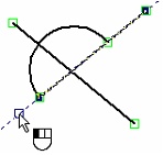
Using snaps and defining parameters in the properties window could change the described rules when constructing a segment.
Suppose, when defining the second segment node, a horizontal snap aligned to another node was used. As a result, the node will be created different from the described above; it will be constructed at the intersection of the horizontal line going through the snap node and a line perpendicular to it. If a double snap to a circle was used in the same situation, such as "Vertical tangency-Horizontal tangency", then the segment node will be created at the intersection of the lines, which are the horizontal and vertical tensions to the given circle.
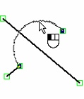
Parameters defined in the command's properties window have a similar effect on the result of auto-parameterization.
For example, if the user defines the X or Y coordinate of the node in the properties window, then the node will be constructed on the vertical or horizontal construction lines with the specified coordinate. If, on the other hand, the offsets dx or dy were defined, then the lines for the node construction will be created parallel to the vertical or horizontal line going through the first node (from which the dx or dy offset was counted). The parallel line parameter will have the value from the respective field of the properties window. If no horizontal or vertical lines go through the node, from which the offset was counted, then those will be automatically created by the system.
When defining an angle value, a line will be created going at the angle to the horizontal; when defining a length value - a circle of the respective radius.
If some parameter value is defined by a variable or expression in the properties window, then that variable or expression will be entered in the parameters of the respective construction line. This rule is applied to all sketch options.
In the case of a combination of any of the described possibilities, a node is created at the intersection of the respective construction lines.
This approach (defining parameters in the properties window) can be combined with using snaps. For example, if only one of the node position-defining parameters is entered in the properties window, and a snap is caught, then, after clicking ![]() , the node will be created at the intersection of the construction lines corresponding to the parameter defined in the properties window, and the snap.
, the node will be created at the intersection of the construction lines corresponding to the parameter defined in the properties window, and the snap.
It is also possible to define only one of the parameters in the properties window and not use any snaps (the precise point position in this case is set by clicking ![]() in the 2D window). In this case, the first of the construction lines, at whose intersection the created node will be positioned, is defined by the specified parameter. As for the second construction line, the following can be used:
in the 2D window). In this case, the first of the construction lines, at whose intersection the created node will be positioned, is defined by the specified parameter. As for the second construction line, the following can be used:
- a vertical or horizontal line (if the X, Y, dx, or dy value was entered in the command's properties window);
- a line at a distance from the start node and perpendicular to the first line (if an angle value was entered in the properties window).
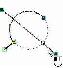
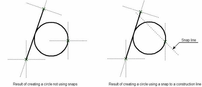
For the second example, let's review constructing a circle tangent to one element. When creating such a circle, a node is constructed after selecting the tangency element, through which the circle should go. In the sketching mode, then the node is created free. In the auto-parameterization mode, it is created as lying on the intersection of two lines (a vertical in the horizontal), or defined by the snaps used in its creation. For example, if snapping to a straight construction line was used to define the node position, then the node will be created lying on the intersection of that line and a horizontal/vertical line going through the specified point. After that, a construction circle is created through the resulting node, tangent to the selected element; it is then used to create a graphic circle.
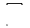
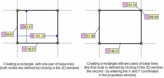
Consider another example - constructing a rectangle. In this case, the user needs to define the nodes of its diagonal corners. The two other nodes, the rectangle side graphic lines and all necessary constructions will be created by the system automatically. The dialog layout in the properties window is fully analogous to the dialog for a simple segment.
The first node of the rectangle is created as a node at the intersection of a vertical and horizontal lines (if its position was picked with ![]() in the drawing window or X, Y coordinates entered in the properties window), or based on the used snaps.
in the drawing window or X, Y coordinates entered in the properties window), or based on the used snaps.
The type of other constructions depends on the method of defining the second rectangle node. If it was defined by simply clicking in the drawing window with ![]() or by defining the dx, dy offsets in the properties window, then the other lines will be created based on the lines of the first node as parallel to them. When defining the position of the second node using the "Length" or "Angle" parameters, then the construction will be created by being also based on the lines of the first node, but according to the specified parameters (similar to the rules described for a segment). Such construction allows obtaining a parametric model of a rectangle with a pair of base lines.
or by defining the dx, dy offsets in the properties window, then the other lines will be created based on the lines of the first node as parallel to them. When defining the position of the second node using the "Length" or "Angle" parameters, then the construction will be created by being also based on the lines of the first node, but according to the specified parameters (similar to the rules described for a segment). Such construction allows obtaining a parametric model of a rectangle with a pair of base lines.
When the second node position of the rectangle is defined by the X, Y coordinates in the properties window or using snaps, the constructions are created independent (or just partially dependent) on the lines of the first node. For example, if the second node of the rectangle was defined with the absolute coordinates in the properties window, then it is created on the intersection of another pair of vertical and horizontal lines. Two other nodes of the rectangle are constructed on the lines parallel to the lines of his first node in going through the second node. As a result, a parametric model is obtained with two pairs of base lines. When editing such a rectangle, two its diagonal nodes will move independent from each other.
Auto parameterization of other line types is done according to similar rules.
Please note that snapping to graphic lines (snapping to a graphic line itself, to an intersection of graphic lines, to a midpoint of a graphic line, etc.) with the purpose of creating nodes and lines of the drawing is implemented by using construction lines underlying the selected graphic lines. By a "construction line underlying a graphic line" we mean a construction line that is geometrically aligned with the given graphic line and serves as its parent.
If a graphic line without a parent construction line was selected for snapping, the system will create the construction line automatically. The created construction line becomes the parent of the graphic line. For example, if a graphic circle line was selected, with a certain radius and the center aligned to a node, then the system will create a construction circle with the center at the same node and the same radius. The new construction line becomes the geometrical basis for the graphic circle line. Similarly, a spline graphic line is converted to a graphic line lying on a construction spline going through the same nodes. For a segment with no underlying construction lines, a line is created that is going through the two segment end nodes.
Another common situation is when the general snapping rules in the auto parameterization mode require creation of a new construction line which would coincide with an existing one. In such a case, the system will be using the already existing line, which helps reduce the number of created construction lines. For example, when making a vertical snap to a node, the system must construct a vertical line going through the selected node. But if there is already a vertical line through that note, the system will use it without creating a new line.
The drawing process in the automatic parameterization mode can be combined with the conventional method of creating a parametric drawing.
Editing sketch
Sketch editing is done by the command "ESK: Edit Sketch". The command is called by one of the following ways:
Keyboard |
Textual Menu |
Icon |
<ESK> |
"Edit|Draw|Sketch" |
|
The command can also be called by pointing at a sketch entity in the command waiting mode and clicking ![]() , or right clicking
, or right clicking ![]() and selecting the item "Edit" in the context menu. Alternatively, the editing command can be accessed directly from the sketch creation command by selecting the option
and selecting the item "Edit" in the context menu. Alternatively, the editing command can be accessed directly from the sketch creation command by selecting the option ![]() .
.
Sketch lines are treated as regular graphic lines. Thus, for their editing it is also possible to use the command “EG: Edit Graphic Line”.
After invoking this command, the following choices become available:
|
<*> |
Select All Elements |
|
<R> |
Select element from list |
|
<Esc> |
Exit command |
After invoking this command, a user can select the sketch line by pointing at it with the cursor and pressing ![]() . Selected element will be highlighted. Several elements can be chosen either by using selection with a window or by selecting successively several elements with the help of <Shift>+
. Selected element will be highlighted. Several elements can be chosen either by using selection with a window or by selecting successively several elements with the help of <Shift>+![]() . To undo selection of the element, the mouse
. To undo selection of the element, the mouse ![]() together with the pressed left key <Ctrl> can be used.
together with the pressed left key <Ctrl> can be used.
After choosing one or several sketch lines the following options will be available in the auto-menu:
|
<P> |
Set selected Element(s) Parameters |
|
<Alt+P> |
Copy Properties from Existing Element |
|
<I> |
Select Other Element |
|
<Del> |
Delete selecting Elemet(s) |
|
<Esc> |
Cancel selection |
If only one line is selected, the following option also appears in the automenu:
|
<O> |
Create Name for selected Element |
When editing sketch lines, please pay attention to the status of the ![]() icon in the system panel. If it is disabled, then editing will be done in the sketching mode. When the option is enabled, editing will be done in the automatic parameterization mode. In this mode, just like when creating a sketch, the system will be slipping construction elements tied by parametric relations beneath the edited lines. In addition, the system will attempt to parameterize not only the edited elements themselves, but also the lines that will be employed for the editing. For example, if the position of one of a sketched line segment nodes is changed in the automatic parameterization mode by defining its new position with an object snap to another sketched line, then construction lines will be slipped beneath both segments.
icon in the system panel. If it is disabled, then editing will be done in the sketching mode. When the option is enabled, editing will be done in the automatic parameterization mode. In this mode, just like when creating a sketch, the system will be slipping construction elements tied by parametric relations beneath the edited lines. In addition, the system will attempt to parameterize not only the edited elements themselves, but also the lines that will be employed for the editing. For example, if the position of one of a sketched line segment nodes is changed in the automatic parameterization mode by defining its new position with an object snap to another sketched line, then construction lines will be slipped beneath both segments.
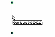
Editing a Line Segment
After selecting a line segment, select one of the segment nodes, the one to move. At this moment, new coordinates can be defined for the selected node in the property window. Besides, after selecting the node, the segment starts rubberbanding. The rubberbanding image defines the new position of the segment being edited. Rubberband the segment by the mouse to the desired position and click ![]() . This fixes the segment in the new position.
. This fixes the segment in the new position.
Editing a Circle, Ellipse, Arc and Elliptical Arc
If the selected element is a circle, ellipse or an arc (except an arc through three points), the second click ![]() on the selected entity launches the mode of editing the radius of the circle, ellipse or arc. A new value of the radius (diameter) can also be assigned via the property window or by rubberbanding the entity image to the desired position and clicking
on the selected entity launches the mode of editing the radius of the circle, ellipse or arc. A new value of the radius (diameter) can also be assigned via the property window or by rubberbanding the entity image to the desired position and clicking ![]() .
.
This way of editing is not suitable for an arc constructed through three points, and an elliptic arc. In this case, after selecting the arc, you need to select a node the arc is passing through, and move it to the desired position or enter the new placement coordinates of the node in the property window.
There is yet another way to modify any type of an arc or fillet. Select one of the end nodes of the selected arc, and then move the rubberbanding image of the arc into the desired position.
After selecting the arc of a circle an additional option becomes available in the automenu:
|
<Tab> |
Change Arc Direction |
This option replaces the selected arc with another arc of the same circle. When applying this option to the arc constructed by 3 points, the middle (second) node of the initial arc is automatically removed.
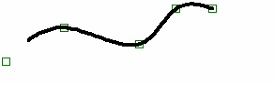
Editing Spline
After selecting a spline, the automenu gets an additional option:
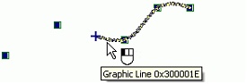
![]() <Ctrl+X> Switch to "Insert Point" mode
<Ctrl+X> Switch to "Insert Point" mode
This option allows adding an additional point to a spline. After calling the option, select a spline node nearest to the additional node location. Then pick the side where the new node should be created with respect to the selected node, and then define its position.
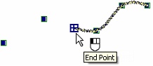
To edit an existing node, select it after selecting the spline. The node and the whole spline will start rubberbanding following the pointer. The new position of the node can be specified by simply moving the pointer to any location and clicking ![]() , or by specifying new coordinates of the node in the property window. The same window provides for entering the new weight value of the node (for splines by control polygon), as well as the number of spline segments.
, or by specifying new coordinates of the node in the property window. The same window provides for entering the new weight value of the node (for splines by control polygon), as well as the number of spline segments.
To delete an existing spline node, select the node and then use the option ![]() .
.
When editing a spline that was divided or trimmed, one can also change the position of the trimming points (the intersection points) of the spline image. These points are highlighted when the spline is selected, and become available for selection. The selected point can be moved along the spline and fixed at a new position by clicking ![]() .
.
When selecting the open spline for editing by nodes, the options for specifying directions of the tangent vectors for the spline end points will be also available in the automenu:
|
<F> |
Set direction at Spline start |
|
<E> |
Set direction at Spline end |