Hatches and Fills |
  
|
Hatches and Fills |
|
Hatches and fills are created by the command "H: Create Hatch". Hatches are used, besides the primary purpose, as a means of various manipulations: as contours for hidden line removal, as profiles and as base data for creating three-dimensional models (in T-FLEX CAD 3D only).
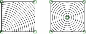
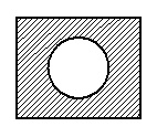
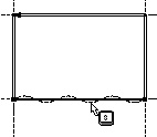
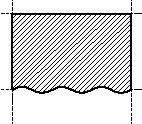
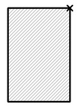
The hatch or fill area may consist of a single or multiple contours. The left diagram shows a single-contour hatch, and the right one – a three-contour hatch.
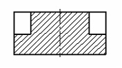
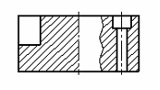
Since the contour lines are "tied" to construction elements, modifications of the latter result in appropriate adjustment of the boundaries of hatch contours.
Various hatch attributes provide control over the contour filling pattern, ranging from standard to special technical ones to even various artistic types. Fills provide filling of the profile area with the specified color.
Custom hatch types can be defined if not found among the standard ones provided by T-FLEX CAD. See details in the chapter "Creating Custom Lines and Hatches".
Applying hatches
Enter the command "H: Create Hatch". The command is called as:
Icon |
Ribbon |
|---|---|
|
Draw → Draw → Hatch |
Keyboard |
Textual Menu |
<H> |
Construct > Hatch |
The following options are available to the user:
![]() /
/![]() <Ctrl><F> Free mode on/off toggle
<Ctrl><F> Free mode on/off toggle
![]() <P> Set selected Element(s) Parameters
<P> Set selected Element(s) Parameters
![]() <Alt+P> Copy Properties from Existing Element
<Alt+P> Copy Properties from Existing Element
![]() <F5> Preview mode
<F5> Preview mode
![]() <X> Automatic Contour search parameters
<X> Automatic Contour search parameters
![]() <A> Automatic Contour search mode
<A> Automatic Contour search mode
![]() <A> Manual Contour input mode
<A> Manual Contour input mode
![]() <N> Select Node (in Manual Contour input mode)
<N> Select Node (in Manual Contour input mode)
![]() <C> Create full Circle Contour (in Manual Contour input mode)
<C> Create full Circle Contour (in Manual Contour input mode)
![]() <E> Create full Ellipse Contour (in Manual Contour input mode)
<E> Create full Ellipse Contour (in Manual Contour input mode)
![]() <S> Create full Spline or Polyline Contour (in Manual Contour input mode)
<S> Create full Spline or Polyline Contour (in Manual Contour input mode)
![]() <F4> Execute Edit Hatch command
<F4> Execute Edit Hatch command
![]() <Esc> Exit command
<Esc> Exit command
Hatch parameters
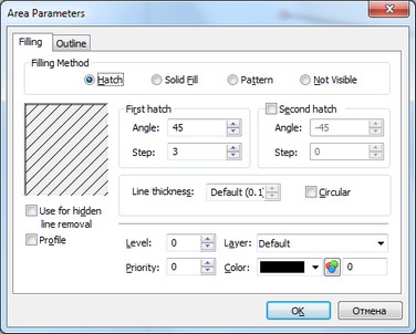
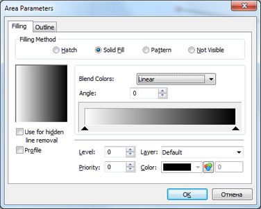
To define hatch parameters, call the option <P>. This will bring a dialog box on the screen, named "Area Parameters". Some of the hatch parameters can be defined on the system toolbar (see the topic "Defining hatch parameters on the system toolbar").
Note that defining parameters prior to inputting the hatch contour makes the settings default for all future hatch creations. To set parameters for one particular hatch, do so in the middle of the hatch creation.
"Filling" tab
Common parameters for all types of filling
Filling method. This item defines the way of filling the contour. The parameters for each of the ways are described below.
Use for hidden line removal. In this case, the contour will be used for removing hidden lines. Any elements with lower priority will be hidden behind the hatch. This is true for assemblies as well.
Profile. With this parameter set, the hatch will be used as a profile for generating a profile file in the command "PR: Write Profile". This is necessary for displaying geometrical information about the contour of a part for further processing.
Level. This is an integer in the range from -126 to 127. The level defines whether the hatch will be displayed upon a redraw.
Priority. This is an integer in the range from -126 to 127. The priority defines the order of drawing graphic elements on the screen (the greater the priority, the "more prominent" is the element).
Layer. Defines the name of the current layer.
Color. The hatch color can be selected from a table or by number (0-256).
Hatch parameters
A hatch can be filled with solid lines with any slant angle in one or two directions.
Angle. The slant angle in degrees with respect to the X-axis.
Step. The distance between hatch lines.
Second hatch. With this attribute set, hatching is done in two directions.
Line thickness. Defines the hatching line thickness.
Circular. With this flag on, hatching is done in concentric circles with specified parameters (step, color, line thickness, etc.). In the case attachment point is not selected, the position of the center is defined by the system automatically. Otherwise, the center is placed in the attachment point.
Fill parameters
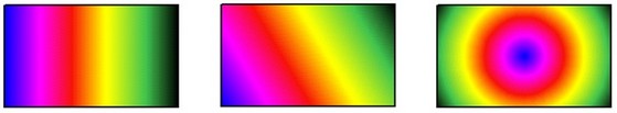
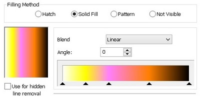
A fill type is defined by the “Blend Colors” options.
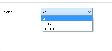
You can make the following choices in the drop-down list:
No. Filling is done with solid color. This hatch does not have additional parameters, besides the common ones for all filling methods.
Linear. This fill uses a linear color transition. The scale displayed in the parameters dialog shows the fill palette. By default, a scale of gray is used for the color transition (from white through tones of gray to black).
The scale palette can be modified by defining arbitrary colors in arbitrary quantities.
To define a new color, double-click ![]()
![]() anywhere on the scale. A standard Windows dialog for defining color will appear. After selecting a color and closing this window, the specified color will appear on the scale. A color position on the hatch transition scale is indicated with a triangular marker below the scale. Using the marker, you can set the new position of the color on the scale. To do this, point to the desired marker, depress
anywhere on the scale. A standard Windows dialog for defining color will appear. After selecting a color and closing this window, the specified color will appear on the scale. A color position on the hatch transition scale is indicated with a triangular marker below the scale. Using the marker, you can set the new position of the color on the scale. To do this, point to the desired marker, depress ![]() and, while holding the button down, drag the marker to the desired position.
and, while holding the button down, drag the marker to the desired position.
To delete a color from the transition scale, drag its marker out of the scale. To modify one of the transition scale colors, double-click ![]()
![]() on the respective color marker.
on the respective color marker.
You can also use the context menu accessible by right clicking ![]() on the scale image in order to set up the color transition scale.
on the scale image in order to set up the color transition scale.
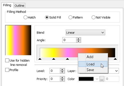
A color scale setting can be saved into an external file “*.col” in order to quickly load it in the future.
An additional parameter “Angle” defines the fill rotation angle.
Circular. This is a fill with a circular color transition. Its parameters are similar to those of a fill with the linear color transition, except for the fill angle (it is not defined for a circular hatch).
You can define the center of a fill with a circular transition. To do this, when editing such a field, define its start point. For details, refer to the section “Editing Hatches and Fills”, the topic “Defining the Hatch Start Point”.
Filling pattern parameters
With this area filling method, the hatch type is defined by a description stored in a file of a special format. The descriptor file of the standard T-FLEX CAD hatches is stored in the "PROGRAM" folder under the name "TCAD.PAT". The name of the standard hatch pattern file is defined in the command "Customize|Options…".
The same format is used for the hatch pattern descriptor file as in AutoCAD system. If some type of hatching is not available, it can be created by the user or copied from AutoCAD system.
In the cases when standard hatches do not suit the user, then user-defined hatch types can be created. Special format files "*.grb" are used for the user-defined hatch descriptors. These files are located in the …/Program/HatchPatterns folder. More on this is in the chapter "Creating user lines and hatches".
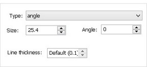
The additional parameters of filling by pattern include:
Type. Defines the filling pattern. The type is selected from a list containing standard and user-defined hatch types.
Size. Defines the scale factor of the pattern hatch. With a very small scale factor the hatch may appear as a solid fill.
Angle. Defines the slant angle of the hatch.
Line thickness. Defines line thickness, used when drawing a hatch by pattern.
Not Visible hatch
With this hatch type set, the hatch will not have its own graphical representation on the drawing. This may be necessary if the hatch is used solely for hidden line removal, or for creating a 3D profile or a 3D model.
"Outline" tab
The hatch contour can additionally be outlined with lines. This is handy when the hatch contour is defined based on construction lines and nodes, in the absence of graphic lines. The hatch outline lines are set up in the same way as common graphic lines.
Defining hatch parameters on the system toolbar
When creating and editing a hatch, some of the parameters can be defined directly in the system toolbar, without using the <P> option:
Color box ![]() . Indicates the line color of the hatch being created or edited.
. Indicates the line color of the hatch being created or edited.
Fill method box ![]() . Defines the hatch contour filling method.
. Defines the hatch contour filling method.
"Use for hidden line removal" icon ![]() .
.
Depending on the fill method setting, the system toolbar may have additional fields:
Hatch:
Hatch slant angle input box ![]() .
.
Hatch line step input box ![]() .
.
By pattern:
Hatch slant angle input box ![]() .
.
Hatch scale factor input box ![]() . Defines the scale factor of the hatch.
. Defines the scale factor of the hatch.
Pattern type input box ![]() .
.
Copying Parameters from Existing Hatches
The values of parameters of the hatch being created can be quickly copied from an already existing hatch. To do so, use the option:
|
<Alt+P> |
Copy Properties from Existing Element |
This option is available in the automenu of the command before creation of the hatch has started or during the process of its creation.
After the option is invoked, it is sufficient to indicate the hatch whose parameters' values must be transferred to the hatch being created.
To assign the copied values of parameters to all new hatches, enable the additional option before selection of the original hatch:
|
<S> |
Set Properties as Default |
When this option is enabled, the copied parameters will be stored as default parameters.
This option simplifies creation of hatches with identical parameters. However, it does not allow us to copy individual parameters or parameters from an object of another type. In such cases, it is more convenient to use the general mechanism of editing parameters of the elements in the properties window.
Hatch Result Preview
There is an option to view the result of hatching without confirming the operation’s creation in the command:
|
<F5> |
Preview mode |
When this option is enabled, in case of presence of a closed contour or contours, the hatch being created is immediately displayed on the screen with the same parameters as defined in the command.
Defining hatch contour
The hatch contour can be defined in two modes, the automatic contour search mode and the manual contour input mode.
Automatic Hatch Contour Search Mode
To activate this mode, press the ![]() icon in the automenu or type <A> on the keyboard. This mode works only with the graphic line contours. To find a hatch contour, position the pointer at a point lying inside the anticipated hatch contour, and click
icon in the automenu or type <A> on the keyboard. This mode works only with the graphic line contours. To find a hatch contour, position the pointer at a point lying inside the anticipated hatch contour, and click ![]() . The found contour will be highlighted. If automatic contour search lasts longer than three seconds, a window is displayed with the [Cancel] button.
. The found contour will be highlighted. If automatic contour search lasts longer than three seconds, a window is displayed with the [Cancel] button.
Successful definition of a hatch contour requires the graphic lines to form "tight" contour (with no gaps).
The result of the automatic tracing is affected by the parameters set for this mode. The automatic search parameters are defined in a dialog called by the option ![]() . In this dialog window, first of all specify the types of the graphic lines to be considered in the automatic search for the hatch contour.
. In this dialog window, first of all specify the types of the graphic lines to be considered in the automatic search for the hatch contour.
The threshold value of the gaps between graphic lines is determined by the parameter "Gap". If the graphic lines pass at the distance, which is less than or equal to that defined by the given parameter, then the system will assume that they have an intersection point and may therefore include them in the hatch contour.
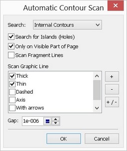
The "Search:" parameter allows defining more specific requirements to the result of tracing a hatch contour. If this parameter has the "External contour" value, then the system will search for the largest closed contour. The internal contours are ignored in this case. When using the "Internal Contours" value, the system finds the minimal contour which still contains the position of the pointer while searching. The internal contours processing depends in this case on the state of the additional flag "Search for Islands (Holes)". If this flag is set, then be found internal contours are included in the resulting hatch contour (so that the identified islands are not filled with a hatch). When the flag is cleared, the internal contours are ignored.
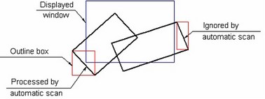
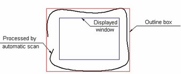
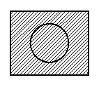
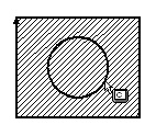
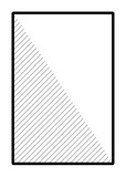
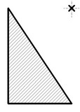
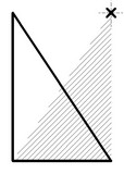
Scanning for hatch contours may take a while on very crowded drawings. Search can be restricted per the “Only on Visible Part of Page” flag. In this case, only the entities will be processed whose outline boxes overlap with a portion of the drawing display on the screen. An outline box is the least horizontally oriented rectangle that fully covers the entity. Examples of outline boxes and contour processing situations are shown on the following diagrams.
“Scan Fragment Lines” flag will add lines of 2D fragments for scanning the hatch contour. This flag is set off by default meaning that lines of the fragments will not be considered when searching the closed contours.
Several contours can be selected subsequently. Should there be common graphic lines between different contours, the contours get automatically joined along these lines.
Manual hatch contour input mode
When manually defining a hatch contour, object snapping is active. Moving the cursor over a drawing element modifies the cursor appearance accordingly and pre-highlights the element. The object snapping can be turned off by pressing on the ![]() icon on the “View” toolbar. In complicated situations, when snapping to the right element is difficult, the elements can be selected by typing commands on the keyboard as described below.
icon on the “View” toolbar. In complicated situations, when snapping to the right element is difficult, the elements can be selected by typing commands on the keyboard as described below.
If you would like to use already created construction entities as a contour, make sure to be in the constrained drawing mode rather than in free drawing. See that the icon ![]() appears in the automenu.
appears in the automenu.
The first step in the manual definition of a hatch contour is selection of the start point. One can select an appropriate 2D node, or create one by clicking at an intersection of construction lines. Next, define the contour sequentially.
The following options become available after selecting a node:
|
<Ctrl><F> |
Free Mode On/Off toggle |
|
<End> |
Close Contour |
|
<Tab> |
Change arc direction (available when making contour along a circle) |
|
<Space> |
Select Graphic line (available after selecting a node) |
|
<N> |
Select Node |
|
<L> |
Select Line |
|
<C> |
Select Circle |
|
<E> |
Select Ellipse |
|
<S> |
Select Spline |
|
<A> |
Select contour automatically |
|
<BackSpace> |
Delete last Contour segment |
|
<Esc> |
Cancel selection |
The simplest way of defining a hatch contour is using the <Space> bar that will let you traverse the contour by following graphic lines. Note that this way can only be used when the hatch contour follows graphic lines. In the case of multiple choices, the cursor should point at the desired graphic line when pressing the <Space> bar.
For faster selection, use the <A> option that automatically searches for the next contour line until the contour is closed or a dubious situation is encountered (such as branching lines).
The system can be set up for selecting only construction lines when defining a hatch contour in snapping mode, and not graphic lines. This option can be set in the system customization dialog box under "Customize|Options…", the "Snap" tab.
A contour can be defined using the same actions as in graphic line creation. That's defining subsequently the lines of the contour, each having the start and end nodes and is constrained to construction entities – a line, a circle, an ellipse or a spline. To define the start or end of a line of the contour, select existing nodes (the <N> key) or create new ones (the <Enter> key or ![]() ) at two-line intersections.
) at two-line intersections.
As in graphic entity creation, to define an arc one needs first select a start node on the arc, and then select the circle by typing <C>. Otherwise, the contour will gain the segment between the two nodes instead of the arc.

When creating a contour along an arc, the arc direction can be flipped by the option ![]() .
.
To create a full circle contour, point at the circle and type <N>. Similarly, ellipses, splines, 2D paths and functions can be included in a contour.
In complex cases, when several nodes coincide, the end nodes of the contour lines can be specified by selecting two construction lines whose intersection yields the desired node. This is done in object snapping mode via the options <L>, <C>, <E>, <S>, for lines, circles, ellipses and splines respectively.
In dubious cases, when several construction lines intersect in one point, all necessary nodes can better be created in advance by using the command "N: Construct Node". The contour then can be defined using the option <N>.
To cancel the last contour line input use the <BackSpace> key.
If the end node of a contour line coincides with the start node then the contour automatically closes, as indicated by a changed color of contour lines display on the screen.
The contour can also be closed using the option
![]() <End>, <Home> Close Contour
<End>, <Home> Close Contour
This closes the contour with a straight line from the current node to the contour start.
If the hatch contains several contours then the next contour can be input after closing the current one.
To complete hatching, upon defining the contours use the following option:
![]() <End> Finish input (creates hatching)
<End> Finish input (creates hatching)
The hatch area then gets filled according to the defined hatch parameters.
To confirm the hatch user can also apply the dynamic toolbar.
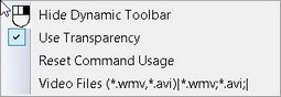
In case if the user wants to refuse the usage of this capability in the given mode, it can be disabled by using the "Do not use in current command" command found in the context menu invoked for the given toolbar.
To cancel an action of a contour segment input or the whole contour definition, right-click ![]() or press <Esc> key. Upon clicking
or press <Esc> key. Upon clicking ![]() the "Right button action" dialog box pops up. You can select the command to execute in this dialog:
the "Right button action" dialog box pops up. You can select the command to execute in this dialog:
Cancel element creation. This cancels hatch contour input.
Cancel last element selection. This cancels the input of the last segment of the hatch contour, bringing the contour definition one step back.
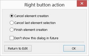
Finish element creation. This command closes the contour automatically with a straight line.
The dialog box won't be displayed again if the option "Don't show this dialog in future" was set. The right mouse button click will in this case execute the command checked in the dialog box last time it was used.
Editing hatches and fills
To modify hatches or fills, use the command "EH: Edit Hatch".
Keyboard |
Textual Menu |
Icon |
<EH> |
"Edit|Draw|Hatch" |
|
Select a hatch or a fill by clicking ![]() . One can also use element selection from list, if the element was named. Upon selecting a hatch or fill, the following actions can be performed:
. One can also use element selection from list, if the element was named. Upon selecting a hatch or fill, the following actions can be performed:
Modifying hatch or fill parameters
This is done via the option <P> that lets modifying hatch (fill) parameters (see parameter description above). One can change the hatch type, for example, from pattern to solid fill. This will fill the contour per the settings for new fill creation.
As in hatch creation, some of the parameters are accessible from the system toolbar upon hatch selection.
Deleting the whole hatch or fill
To do this, press the <Del> key (the icon ![]() in the automenu).
in the automenu).
In the case when a hatch is referenced by the 3D model, its direct deletion is impossible. The user will have to delete all dependent elements referencing the hatch, which may not be desirable. In such cases, it may be possible to edit the hatch contour. This opportunity is described below.
As in the case of any other model elements, multiple selection of hatches is supported for simultaneous deletion or modifying their parameters.
Adding a contour to a hatch or fill
This is done similar to hatch (fill) contour initial input. Suppose, given a hatch, we'd like to make a hole within. To do this, select the hatch and turn on the contour addition mode (the icon ![]() or <M> key). Then, using the option <C>, input the additional contour – a full circle, and press <End>. The result will be a hatch with a "cut" hole.
or <M> key). Then, using the option <C>, input the additional contour – a full circle, and press <End>. The result will be a hatch with a "cut" hole.
Redefining hatch contour
Select the hatch whose contour is to be redefined, and use the option
![]() <К> Redefine Hatch Contours
<К> Redefine Hatch Contours
To input a new hatch contour, using manual or automatic contour input mode. The edited hatch will assume the new shape upon confirming the input with the ![]() option.
option.
Defining the hatch start point
A start point can be defined for a hatch (either the regular or by pattern or for a fill with a circular color transition). The start point defines the location from which hatching begins.
The start node can be defined by the option:
![]() <O> Select Starting Node of Hatch
<O> Select Starting Node of Hatch
Upon calling the option, simply click the desired node with ![]() .
.
To reject the start node input, use the option:
![]() <T> Cancel selection of starting Node of Hatch
<T> Cancel selection of starting Node of Hatch
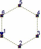
Displaying the contour point numbers of a hatch
To toggle the display of the contour point numbers of a hatch, use the option:
![]() <Q> Show/Hide contour point numbers
<Q> Show/Hide contour point numbers
With the option turned on, the points in the all hatch contours are enumerated based on their position in the contours and the contours direction. Points, belonging to the different contours, are enumerated independently. The point numbers are displayed next to the respective nodes. When several subsequent points of a contour coincide, their numbers are displayed next to each other, separated by commas.
Editing a particular contour
Note: only manually defined hatch contours can be edited.
First, select the hatch that includes the desired contour. Then, turn on the contour editing option using the option:
![]() <М> Contour edit mode
<М> Contour edit mode
Now, select the desired contour. The selected contour can be deleted or edited. To delete it, press the <Del> key. When picking a contour, the segment of the contour nearest to the cursor gets automatically selected. Now, the necessary modifications can be done with the help of the automenu.
The following options become available upon selecting a contour segment:
|
<I> |
Switch to “Insert Point” mode |
|
<Q> |
Show/Hide contour point numbers |
|
<Del> |
Delete selected Contour |
|
<R> |
Change Contour direction |
|
<F> |
Move Contour starting point forward |
|
<B> |
Move Contour starting point backward |
|
<N> |
Select Node |
|
<L> |
Straighten Contour Segment |
|
<C> |
Select Circle |
|
<E> |
Select Ellipse |
|
<S> |
Select Spline |
|
<Tab> |
Change arc direction (available when editing an arc segment of a contour) |
|
<A> |
Link Arc or Circle to Node |
|
<K> |
Break Link with Node |
|
<Esc> |
Cancel selection |
Note: the options ![]() and
and ![]() only are available for editing the contours defined automatically with the option
only are available for editing the contours defined automatically with the option ![]() , constructed on top of 2D projections or as a copy of an existing hatch.
, constructed on top of 2D projections or as a copy of an existing hatch.
When editing a contour, the following actions are supported: node deletion, node addition and redefinition of the type of lines connecting the nodes. Besides, one can change the contour direction, move the start point back and forth, link arc segments of a contour to nodes.
Flipping contour direction to the opposite
The contour direction is an important hatch property when creating 3D elements. This parameter is inherited by the 3D profiles created based on hatches. For example, the 3D operation "Loft" matches profiles by the start points of the respective contours and requires matching of contour directions as well.
To change the direction of a 3D profile constructed based on a hatch, you need to change the hatch contour direction.
The contour direction is shown by the arrow displayed upon selecting the contour. This arrow also indicates the start point of the contour.
The following steps are to be done in order to change a hatch contour direction:
- Call the command "EH: Edit Hatch";
- Select a hatch for editing;
- Turn on the contour editing mode (the icon ![]() or <M> key);
or <M> key);
- Select the contour (point the graphic cursor at and click ![]() );
);
- Flip the contour direction (the icon ![]() or <R> key);
or <R> key);
- Confirm changes by the ![]() icon or <End> key.
icon or <End> key.
Moving around contour start
The contour start is the first node selected during the manual hatch contour input.
If the contour is defined automatically or without node selection (as by a full circle), the start point is defined automatically.
The start point placement and contour direction (see above) can only be changed for the contours defined manually.
To move the contour start point, do the following steps:
- Call the command "EH: Edit Hatch";
- Select a hatch for editing;
- Turn on the contour editing mode (the icon ![]() or <M> key);
or <M> key);
- Select the contour (point at it with the graphic cursor and click ![]() );
);
- Move the start point forward (the icon ![]() or <F> key) or backward (the icon
or <F> key) or backward (the icon ![]() or <B> key);
or <B> key);
- Confirm changes by the ![]() icon or the <End> key.
icon or the <End> key.
Editing a particular segment in contour
To edit a contour segment, do the following steps:
- while in contour editing mode, select the desired contour segment;
- select the construction element defining the new contour segment: line, circle, ellipse or spline (use the appropriate option for element selection). The end nodes of the contour segment must be snapped to the selected construction element;
- confirm changes by the ![]() or <End> key.
or <End> key.
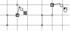
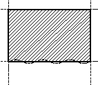
Let's review an example illustrating a particular contour segment editing. The diagram shows the original hatch constructed along construction lines using the "Outline" option. Here, a straight-line segment is to be replaced by a spline. To do so, call the command "EH: Edit Hatch" and select the hatch.
Then, turn on the contour editing mode using the option:
![]() <M> Contour edit mode
<M> Contour edit mode
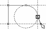
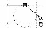
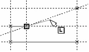
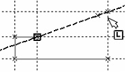
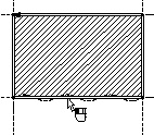
Select the hatch contour. The following diagram shows the situation after the hatch selection. The contour is highlighted, and the nodes are marked by little boxes. Move the cursor over the desired segment of the contour and click the left mouse button. The selected contour segment also gets highlighted, and the nodes marked by larger boxes. This state is shown on the center diagram. Move the cursor over the spline constructed through the nodes of the contour being edited, and select it as a contour segment by typing <S>.
Similarly, one can replace a contour segment by an arc or ellipse, if the respective circle or ellipse is constructed based on the marked nodes. Simply use the appropriate option: <C> or <E>. If the new contour segment was not constructed based on the marked nodes yet passes through them then the contour segment editing should be done via the option "Switch to 'Insert Point' mode" (the icon ![]() or <I> key). This option functionality is described below.
or <I> key). This option functionality is described below.
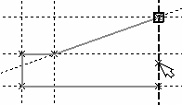
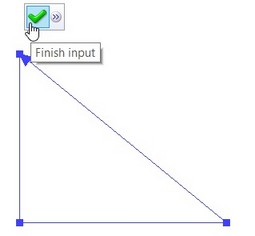
The edited segment will then assume the desired shape. The system is still in the mode of modifying the selected contour segment. If the manipulations with this segment are over, complete the contour segment modification mode. To do so, press the ![]() icon in the automenu.
icon in the automenu.
The option <Space> is not available for editing the contour. Therefore, it is impossible to snap a contour line to a graphic line. If a contour segment is to be replaced by a graphic line while editing, as, for instance, a wave line, then you need to construct a spline based on the wave line. The intended hatch contour segment can then straightforwardly be replaced by the spline.
Linking arc contour segment to helper node
If the edited contour segment is an arc then the option for linking to a helper node ![]() becomes available in the automenu. This node will be defining the choice of an arc constructed on top of the circle to be used for the hatch contour. As the drawing gets modified, the hatch contour will pass by the arc nearest to the linking node.
becomes available in the automenu. This node will be defining the choice of an arc constructed on top of the circle to be used for the hatch contour. As the drawing gets modified, the hatch contour will pass by the arc nearest to the linking node.
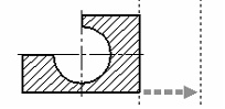
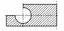
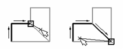
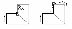
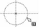
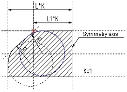
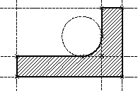
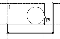
Let's review an example where a construction line position is modified with respect to a reference line driven by a variable "K". Both circles here are linked to a node on the drawing in order to ensure correct position. The left diagram shows the hatch contour in the original configuration (K=1). Let's link the arc segment of the hatch contour on top of the outer circle to the marked node. To do this, do the following steps once in "EH: Edit Hatch" command:
- Call the hatch contour editing option ![]() ;
;
- Select the arc;
- Call the option ![]() ;
;
- Select the linking node.
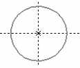
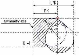
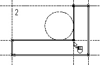
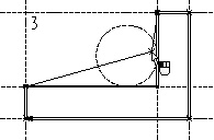
The right diagram shows the modified drawing with the "К" equal to (-1). The contour segment on top of the upper circle was linked to the marked node and adjusted correctly. The contour segment on top of the second circle was not linked to the node, which resulted in an incorrect configuration.
To clear or redefine the linking node, use the option ![]() .
.
Deleting a node on a contour
To delete a node on a contour, do the following steps:
- Call the command "EH: Edit Hatch";
- Select a hatch for editing;
- Turn on the contour editing mode (the icon ![]() or <M> key);
or <M> key);
- Select the contour segment the node is snapped to (point at with the graphic cursor and click ![]() );
);
- Select the node (point at with the graphic cursor and click ![]() );
);
- Delete the node (the icon ![]() or <Del> key);
or <Del> key);
- Confirm changes (the icon ![]() or the <End> key). The resulting new hatch contour passes through two adjacent nodes.
or the <End> key). The resulting new hatch contour passes through two adjacent nodes.
Modifying a contour node position
To modify a contour node position, do the following steps:
- Call the command "EH: Edit Hatch";
- Select a hatch for editing;
- Turn on the contour editing mode (the icon ![]() or <M> key);
or <M> key);
- Select the contour segment of the node (point at with the graphic cursor and click ![]() );
);
- Select the node (point at with the graphic cursor and click ![]() );
);
- Move the node to the desired position (the contour rubberbands after the cursor as the node is being dragged);
- Fix the node (click ![]() over an intersection point or type <N> key for an existing node);
over an intersection point or type <N> key for an existing node);
- Confirm changes (the icon ![]() or the <End> key). As a result of moving, the node point will be connected with the neighbor nodes by straight line segments belonging to the contour (regardless of the former adjacent segment entity types).
or the <End> key). As a result of moving, the node point will be connected with the neighbor nodes by straight line segments belonging to the contour (regardless of the former adjacent segment entity types).
Creation of additional nodes on a contour
To create additional nodes on a contour, do the following steps:
- Call the command "EH: Edit Hatch";
- Select a hatch for editing;
- Turn on the contour editing mode(the icon ![]() or <M> key);
or <M> key);
- Select the contour segment to split by new node(s) (point at with the graphic cursor and click ![]() );
);
- Turn on the point insertion mode (the icon ![]() or the <I> key), and click on a contour segment. The segment becomes split in two, with the new node between them. The node and the segments rubberband with the cursor, the solid line segment connecting to the previous node and the dashed line one to the next. The order of the nodes after the insertion will be determined by the system automatically, depending on the hatch contour direction. Do not click on a segment near a vertex, as, instead of adding a node, this will start moving the existing node;
or the <I> key), and click on a contour segment. The segment becomes split in two, with the new node between them. The node and the segments rubberband with the cursor, the solid line segment connecting to the previous node and the dashed line one to the next. The order of the nodes after the insertion will be determined by the system automatically, depending on the hatch contour direction. Do not click on a segment near a vertex, as, instead of adding a node, this will start moving the existing node;
- Close the contour between the newly created node and the successive one.
Contour input is complete once the closing node is selected, or the icon ![]() or the <End> key is pressed.
or the <End> key is pressed.
The system returns to the mode "Contour selected for editing". One can do other modifications, and then confirm all changes.
- Confirm changes (the icon ![]() or the <End> key).
or the <End> key).
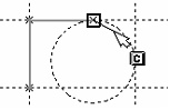
Let us illustrate the above with a specific example. Suppose, a hatch contour needs to be edited that was originally constructed along construction lines using the "Outline" option. The original and target configurations are shown on the diagrams.

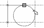
To get the result, begin with calling the command "EH: Edit Hatch". Next, select the hatch and turn on the contour editing mode. Select the hatch contour to be modified. Now, to get the result, perform manipulations shown on the following diagrams 1 – 8.
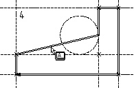
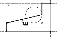
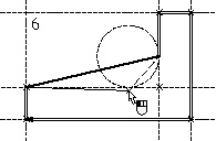
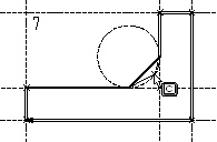
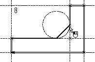
Upon selecting the closing node (see diagram 8) the contour automatically closes, and the point insertion mode exits. What is left is to press the ![]() icon or the <End> key, and the contour editing task is completed.
icon or the <End> key, and the contour editing task is completed.
One comment to the described procedure: as the contour segment to be modified is selected (see diagram 5), the system will define the previous and the next nodes in the sequence, depending on the hatch contour direction. These will be identified by the dashed and solid rubberbanded lines. In this particular example, the hatch contour direction is clock-wise.