Nodes |
  
|
Nodes |
|
Node is a point whose coordinates are calculated depending on the node parameters or position of other model elements. Nodes are important construction elements in T-FLEX CAD. They represent start and end points of graphic lines. Nodes are directly involved in creation of most of the graphic elements. They also play an important role in creation of construction entities.
Creating nodes
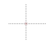
T-FLEX CAD supports nodes of various types, depending on the relation with other model elements. Most common are nodes constructed at an intersection or at a tangency point between two construction lines. Such nodes are displayed as small x-shape crosses.
Other types of nodes are displayed differently on the screen.
There are following types of nodes:
1. Node at intersection of construction lines. Such nodes are used most often in creation of parametric models. Its position is defined by the position of two construction entities and their intersection to which the node is related. In the case of multiple intersections between the entities, the particular intersection shall be identified.
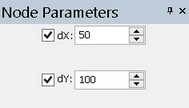
2. Free node is defined by the absolute X and Y coordinates in the model coordinates. The values of a free node coordinates can be defined by variables. Such nodes are of limited use in parametric models being created, however, these are widely used in development of sketches, various diagrams and technical figures. Free nodes are useful in the cases when there is no strict requirement on positioning points of the image.
3. Node from fragment is defined by the position of another node located on a fragment of an assembly. This type of node is necessary for creation of parametric assemblies. It is used for relating some element of an assembly with a point on a fragment of this assembly.
4. Node created relative to another node. Its position is defined by an offset from another node. The offset values can be defined by constants or by variables. A node of this type can be used as an auxiliary fixing point in the cases when some element should be snapped at an offset position of the base node rather than to that node directly.
5. Node lying on a construction entity, at the specified distance from another node along the entity.
6. Node – a characteristic point of a construction entity. Among this type are nodes lying at a circle center, at a start or end point of a spline or other curve.
7. Node on a curve, dividing the curve in a specified proportion.
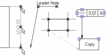
8. Nodes placed at characteristic points of elements. This type includes nodes on dimension witness lines, on leader notes, at the ends of lines created by copying, etc.
For a point to become a node, the node needs to be created. This can be done in various ways:
● By the command "N: Construct Node", specifically designed for creating nodes.
● By the option <Space> in the commands "L: Construct Line" and "C: Construct Circle". In these commands, you can move the cursor over an intersection point of construction entities and press <Space>.
● In the command "G: Create Graphic Line" when creating a graphic line.
● In the command "H: Create Hatch" when creating a hatch.
● In the command "FR: Create Fragment". As you add a drawing as a fragment into the current drawing, you can automatically create nodes from fragment in the drawing.
The last three techniques are described in the chapters that follow. In this chapter we will review in details the command "N: Construct Node".
Icon |
Ribbon |
|---|---|
|
Draw → Construct → Node |
Keyboard |
Textual Menu |
<N> |
Construct > Node |
Upon calling the command, the following options become available in the automenu:
|
<Ctrl><F> |
Free mode on/off toggle |
|
<P> |
Set Node parameters |
|
<L> |
Select Line to create Node |
|
<C> |
Select Circle to create Node |
|
<E> |
Select Ellipse to create Node |
|
<S> |
Select Spline to create Node |
|
<N> |
Select Node for relative Node creation |
|
<F> |
Select Fragment to create Node |
|
<R> |
Select Fragment from list |
|
<W> |
Select 2D Projection |
|
<F4> |
Execute Edit Node command |
|
<Esc> |
Exit command |
The option ![]() /
/![]() allows selecting the drawing mode - "free" or "constrained". The current mode is indicated by the kind of the option icon displayed in the automenu. The option
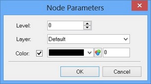
allows selecting the drawing mode - "free" or "constrained". The current mode is indicated by the kind of the option icon displayed in the automenu. The option ![]() , called prior to node creation, opens a dialog box for defining the system-wide parameters, such as layer, level, color for new nodes. The same dialog allows to define position of various types of nodes being created.
, called prior to node creation, opens a dialog box for defining the system-wide parameters, such as layer, level, color for new nodes. The same dialog allows to define position of various types of nodes being created.
Clicking ![]() constructs a node at the nearest intersection point of construction entities, while in "constrained" drawing, or construct a node at the position on the drawing directly under the cursor in "free" drawing.
constructs a node at the nearest intersection point of construction entities, while in "constrained" drawing, or construct a node at the position on the drawing directly under the cursor in "free" drawing.
The options ![]() ,
, ![]() ,
, ![]() and
and ![]() allow creating nodes lying on the selected entities.
allow creating nodes lying on the selected entities.
To construct a node relative to another node, the option ![]() is used.
is used.
The options ![]() ,
, ![]() and
and ![]() help creating nodes based on fragments and on the lines of 2D projections.
help creating nodes based on fragments and on the lines of 2D projections.
Nodes based on construction entities
There are two main ways of creating nodes at intersections of entities in the command "N: Construct Node":
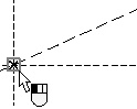
1. Move the cursor over an intersection of two entities and click ![]() . A node is created at this point.
. A node is created at this point.


2. Subsequently create two construction entities. The node is created at their intersection point. Should there be two or more intersections, the one is used that was nearest to the cursor at the time of the last entity selection. The options used for selecting various-type construction entities are ![]() ,
, ![]() ,
, ![]() and
and ![]() .
.
The second way of creating nodes is recommended on crowded drawings and in the cases when more than two entities intersect in one point.
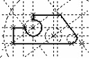
Examples of node creation:
<L>,<L> 


<L>,<C> 


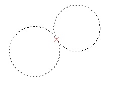
<C>,<C> 


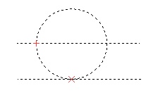
To create a node on a construction circle, select the circle using the option ![]() . A node will start rubberbanding along the circle. The position of the node on the circle can be defined roughly by mouse clicking
. A node will start rubberbanding along the circle. The position of the node on the circle can be defined roughly by mouse clicking ![]() , or exactly in the property window or in the parameters dialog box (the option
, or exactly in the property window or in the parameters dialog box (the option ![]() ).
).
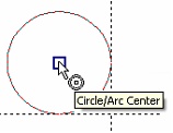
To construct a node at a circle center, select the circle and then use the option ![]() again. With snapping turned on, move the cursor over the center of the circle. The cursor will get the circle mark and the respective tooltip. Clicking
again. With snapping turned on, move the cursor over the center of the circle. The cursor will get the circle mark and the respective tooltip. Clicking ![]() now creates the node.
now creates the node.
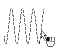
To construct a node at the start or end point of a spline or other curve, select the curve by clicking it with ![]() . A cross-shape node will start rubberbanding along the curve. Move the cursor over one of the endpoints of the selercted curve and engage the option
. A cross-shape node will start rubberbanding along the curve. Move the cursor over one of the endpoints of the selercted curve and engage the option
![]() <Т> Select Curve to create end Node
<Т> Select Curve to create end Node
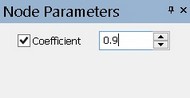
To construct a node on a curve, select the curve, and then define the position of the node on the curve. The position of the node can be roughly defined by ![]() , or specified exactly in the property window or the parameters dialog box (the option
, or specified exactly in the property window or the parameters dialog box (the option ![]() ) by entering the parameter of the node on the curve in the range from 0 (the start point of the curve) to 1 (the end point).
) by entering the parameter of the node on the curve in the range from 0 (the start point of the curve) to 1 (the end point).
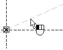
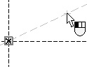
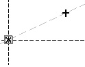
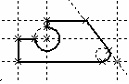
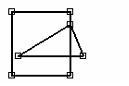
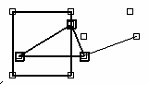
To construct a node relative to another node, with the specified offsets, select the reference node for offsetting using the option ![]() . A cross-shape node will start rubberbanding on the screen with a dashed rubberband connecting it to the reference node. The offsets can be defined freely by clicking
. A cross-shape node will start rubberbanding on the screen with a dashed rubberband connecting it to the reference node. The offsets can be defined freely by clicking ![]() or entered exact in the property window. The offset values in the property window can be specified by constants or variables.
or entered exact in the property window. The offset values in the property window can be specified by constants or variables.

or

The node that divides the distance between two other nodes can also be constructed in case when the original nodes lie on the same line. The resulting node will also belong to this line. To create such a node it is required to successively select the first node (the ![]() option), then select the line (the
option), then select the line (the ![]() option), then the second node (the
option), then the second node (the ![]() option). Location of the node is specified in the same way as in the previous case.
option). Location of the node is specified in the same way as in the previous case.
In the command of node editing “ЕN: Edit node” there is a capability of selection of node’s snapping: the snapping can be associated with intersection of construction lines, circle center, intersection of two snaps (for example, two perpendicular lines), etc. Possible snaps are highlighted with a color when the cursor of the mouse points at them and the command “ЕN: Edit node” is active.
To delete a node or change its parameters, use the command "ЕN: Edit Node":
Keyboard |
Textual Menu |
Icon |
<EN> |
“Edit > Construction > Node” |
|
Selecting a node by ![]() highlights the node and the construction entities whose intersection defines the node position. At an attempt to delete a node referenced by other drawing elements, a dialog of the command for deleting the elements will emerge on the screen with specification of dependent elements and a list of possible actions of the system.
highlights the node and the construction entities whose intersection defines the node position. At an attempt to delete a node referenced by other drawing elements, a dialog of the command for deleting the elements will emerge on the screen with specification of dependent elements and a list of possible actions of the system.
One can also select a node for editing from the command "EC: Edit Construction". Using the option <N> in the command "EC: Edit Construction" automatically brings the system into the command "ЕN: Edit Node".
Nodes and other construction entities can be hidden at any time. To do this, enter the command "SH: Set Levels" and set the lower limit of the visible levels for "Construction" greater than the "Level" parameter value assigned to these entities. By default, all elements have level "0". Setting the lower limit of the visibility range simply to "1" hides construction entities from display.
One can also use layers for making construction entities invisible. Place those on some layer, for example, "Construct", and then make this layer invisible in the command "QL: Configure Layers".
The display size of node symbols can be modified. To do this, use the command "SO: Set System Options". The size in pixels can be specified in the item 2D > Node size in the command dialog.
If extra nodes or construction entities were created for some reason along the design process, these can be quickly deleted using the command "PU: Delete Unused Construction".
Icon |
Ribbon |
|---|---|
|
Edit → Additional → Purge |
Keyboard |
Textual Menu |
<PU> |
Edit > Purge |
This command will delete all construction entities that are not used in the model for defining graphic elements.
"Free" nodes
The main approach to creating drawings in T-FLEX implies use of nodes on the intersections of construction entities. However, the system also supports so-called "free" nodes. These nodes are not the points of entity intersections; rather, these are defined in absolute coordinates. Such nodes can be used just as well as usual "constrained" nodes for creating either construction entities or graphic elements. Free nodes are displayed as squares.
To create such nodes, turn on "free" drawing mode in the command "N: Construct Node" by using the option ![]() /
/![]() .
.
Object snapping engages in free drawing mode similar to that provided in the sketching command. Besides, one can use the grid, with its settings defined in the command "QG: Change Grid settings". The grid helps positioning created nodes more accurately.
To create a node, point the cursor to the desired location on the drawing and click ![]() . The node will be created right under the cursor. The exact position of the node on the drawing can be specified in the property window.
. The node will be created right under the cursor. The exact position of the node on the drawing can be specified in the property window.
A feature of "free" nodes is the provision for moving such node or a group of nodes and, therefore, all elements related to them, by the command "EN: Edit Node".
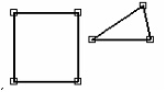
This is impossible for "constrained" nodes. The latter can only be moved by relocating construction entities used for the nodes creation.
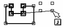
As in the case of other drawing elements, multiple selection is done by the option <*>, or by clicking ![]() while holding down the <Shift> key (adding to the list of selected), or <Ctrl> key (excluding form the list of selected). Generally speaking, the following options are available in the command "ЕN: Edit Node":
while holding down the <Shift> key (adding to the list of selected), or <Ctrl> key (excluding form the list of selected). Generally speaking, the following options are available in the command "ЕN: Edit Node":
|
<P> |
Set selected Element(s) Parameters |
|
<V> |
Mode of dynamic recalculation of model |
|
<O> |
Create name for selected element |
|
<J> |
Join free nodes |
|
<B> |
Break node |
|
<F> |
Convert to free node |
|
<N> |
Select existing node |
|
<I> |
Select other element |
|
<Del> |
Remove selected Element(s) |
|
<Esc> |
Cancel selection |
The mode of dynamic recalculation is enabled by the![]() option. When enabling this mode the node’s editing automatically leads to redrawing of the elements connected with the node. At the same time preview of the elements is shown with the same quality as the final result. The mode of dynamic recalculation of the model enhances the editing’s process intuitiveness. It can be used for editing, for example, schemes, plans, etc.
option. When enabling this mode the node’s editing automatically leads to redrawing of the elements connected with the node. At the same time preview of the elements is shown with the same quality as the final result. The mode of dynamic recalculation of the model enhances the editing’s process intuitiveness. It can be used for editing, for example, schemes, plans, etc.
Let us elaborate on the options ![]() and
and ![]() . These options affect a group of nodes, one of which can be constrained, and the rest - "free". The option
. These options affect a group of nodes, one of which can be constrained, and the rest - "free". The option ![]() unites several nodes into one, adjusting the graphics accordingly.
unites several nodes into one, adjusting the graphics accordingly.

The option ![]() splits a node at a meeting point of multiple graphic entities. Each of the entities gets its own node whose position you can modify.
splits a node at a meeting point of multiple graphic entities. Each of the entities gets its own node whose position you can modify.
Keep in mind that "free" nodes are not recommended for use in parametric drawings. Drawings based on free nodes are similar to those supported by other CAD systems, and lack the advantage of parametric geometrical relations.
The option ![]() is available for nodes, not related to construction entities (for example, nodes from fragment or from 2D projection). This option allows breaking the relation between the node and its original references by converting it into a free node, whose position will not change under modifications to the original reference elements.
is available for nodes, not related to construction entities (for example, nodes from fragment or from 2D projection). This option allows breaking the relation between the node and its original references by converting it into a free node, whose position will not change under modifications to the original reference elements.
The option ![]() is an additional tool for multiple selections. To add a node to the list of selected, simply engage this option and pick the desired node.
is an additional tool for multiple selections. To add a node to the list of selected, simply engage this option and pick the desired node.
Nodes from fragment. Node names
This way of node creation is quite important for support of parametric assemblies. The nodes from fragments provide the means for “tying up” construction entities and graphic elements of the current assembly to the fragment.
Nodes from a fragment can be created automatically when inserting a fragment if in the settings of the system (the “SO: Set System Options ” command, the “Fragments” tab) the “Create named nodes automatically” flag is enabled. In this case while inserting the fragment the nodes will be created on the basis of all named nodes of the fragment.
In addition, nodes from a fragment can be created automatically while creating dimensions and other elements with the use of object snapping if in the “SO: Set System Options ” command, the Snaps > Priority tab, the “Fragment nodes” parameter is enabled. When this flag is disabled, then for creation of nodes on the fragments we need to perform the actions described below.
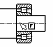
For example, you assembled a bushing on your drawing by the command "FR: Create Fragment", and now want to create a dimension on the outer diameter of the bushing.
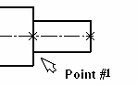
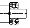
Since a dimension can't be created without nodes, you need to create two nodes from this fragment.
Nodes from fragment can be created in the command "N: Construct Node". With the object snapping mode engaged and the flag Fragment Nodes set (the tab Snap > Priority of the command "SO: Set System Options"), a node from fragment is created as follows. Move the cursor over an end of a fragment graphic line. A node will highlight at the end of the line, with a tooltip saying "Fragment Node". Clicking ![]() creates a node from fragment.
creates a node from fragment.
With the object snapping mode off, first select a fragment via either of the options, ![]() or
or ![]() . The selected fragment will be highlighted.
. The selected fragment will be highlighted.
If the fragment contains the named nodes, they will immediately be seen on the drawing. If necessary, it is also possible to display on the drawing the names of these nodes by enabling the option:
![]() <М> Show Fragment Node Names
<М> Show Fragment Node Names
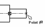
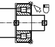
After that, nodes from fragment can be created by pointing the cursor to the desired nodes among the highlighted ones and clicking ![]() . Created nodes from fragment are displayed as crossed diamonds.
. Created nodes from fragment are displayed as crossed diamonds.

The option <A> highlights and makes available for selection all nodes that exist in the fragment.
![]() <A> Show all Fragment Nodes
<A> Show all Fragment Nodes
To assign a name to a node of a fragment drawing, use the following option under the command "EN: Edit Node":
![]() <Ctrl><N> Create Name for selected Element
<Ctrl><N> Create Name for selected Element
Any name is allowed. The node now becomes named and can later be "exposed" upon assembling this drawing elsewhere.
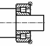
Once the nodes from fragment are created, make the dimension via the command "D: Create Dimension":
Nodes from 2D projections
To create nodes based on the entities of 2D projections, one can use the option ![]() . Upon calling the option, select the desired projection by
. Upon calling the option, select the desired projection by ![]() . The selected projection will be highlighted. After that, moving the cursor over the endpoints of graphic entities on the projection will highlight their nodes. Clicking
. The selected projection will be highlighted. After that, moving the cursor over the endpoints of graphic entities on the projection will highlight their nodes. Clicking ![]() creates a node from projection.
creates a node from projection.
Option ![]() allows the user also to project nodes from a 3D model. After calling the option and selection of projection, it is sufficient to indicate a required 3D node (in 3D window or in the tree of a 3D model). A free node, which is a projection of the given 3D node, will appear on 2D projection.
allows the user also to project nodes from a 3D model. After calling the option and selection of projection, it is sufficient to indicate a required 3D node (in 3D window or in the tree of a 3D model). A free node, which is a projection of the given 3D node, will appear on 2D projection.
Nodes lying on characteristic points of entities
Such nodes can only be created in the object snapping mode. This type of nodes includes nodes lying on dimension witness lines, leader notes, tolerances, as well as on the endpoints of graphic lines copied from or belonging to 2D projections.
The respective option should be checked on the Snap > Priority tab under the command SO: Set System Options.