Lines |
  
|
Lines |
|
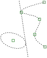
By "line", we mean infinite lines that belong to construction entities and serve as the parametric framework of a drawing. Lines are displayed as thin dashed lines.
Constructing lines
To construct a line, call the command "L: Construct Line".
Icon |
Ribbon |
|---|---|
|
Draw → Construct → Line |
Keyboard |
Textual Menu |
<L> |
Construct > Line |
The following options become available:
|
<P> |
Set Line Parameters |
|
<X> |
Creates two crossing Lines and Node |
|
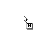
<H> |
Creates horizontal Line |
|
<V> |
Creates vertical Line |
|
<L> |
Selects related Line |
|
<N> |
Selects Node |
|
<C> |
Selects tangent Circle |
|
<E> |
Selects ellipse to create Line |
|
<S> |
Selects spline |
|
<O> |
Create orthogonal Line |
|
<T> |
Creates Proportional Line |
|
<U> |
Create Axis of Symmetry |
|
<A> |
Selects Axis of Symmetry (straight Line) |
|
<W> |
Select 2D projection |
|
<O> |
Create two Lines and Node in (0,0) |
|
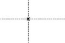
<Space> |
Creates a node at the nearest intersection of construction lines |
|
<F> or <Ctrl><1> |
Create insertion Point for Fragment (xn,yn) |
|
<F4> |
Executes edit Construction command |
Some of these options become available only after selecting certain construction entities.
There are different techniques of creating lines. Some lines are independent of other construction entities. These could be a standalone horizontal or vertical line. Usually, these are the very first lines on a drawing. By creating a vertical and a horizontal line, you define the base lines, to which all the rest will be related.
Other lines require the related elements to be selected at the time of creation. For example, a line tangent to two circles requires the circles to be selected and the tangency condition defined.

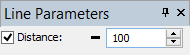
A number of line creation techniques require a certain geometric parameter to be defined. For example, consider constructing a line parallel to another line and passing at a certain distance from the other line. In this case, it is necessary, besides selecting the original line, to define the distance between the lines.
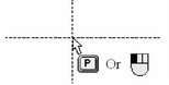
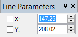
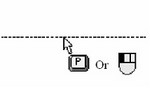
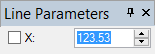
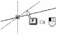
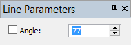
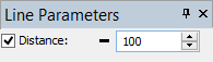
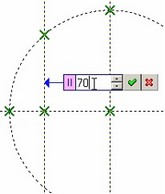
Exact values of the numerical geometric parameters can be entered in the property window in transparent mode. Besides, one can use the line parameters dialog box under the option ![]() , that, besides the geometric parameters, also allows defining general system ones, as level, layer, etc. If exact value is not required, one can simply point at the desired location on the drawing and click
, that, besides the geometric parameters, also allows defining general system ones, as level, layer, etc. If exact value is not required, one can simply point at the desired location on the drawing and click ![]() . In this case, the numerical parameter value is defined by the cursor position.
. In this case, the numerical parameter value is defined by the cursor position.
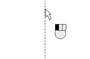
When constructing lines, one should keep in mind that after creating one line the command sticks in the selected line type creation mode. For example, once a pair of crossing lines was created under the <X> option, another pair of crossing lines can be created again without re-selecting the option. This feature helps speed up constructing same-type lines. To quit such a mode, right-click ![]() .
.
The line creation command allows making a variety of construction line configurations by combining the limited set of options, as follows:
<X>,<P> Crossing (vertical and horizontal) lines with a node at the intersection and exactly defined placement coordinates
<H>,<P> Horizontal line with exactly defined coordinates
<V>,<P> Vertical line with exactly defined coordinates
<L>,<P> Parallel to a line, the specified distance away
<N>,<P> Line at a specified angle with respect to X axis
<N>,<L>,<P> Through a node, at a specified angle with respect to a line
<N>,<L>,<O> Through a node, orthogonal to a line
<N>,<N> Through a pair of nodes
<H>,<N> or <N>,<H> Horizontal line through a node
<V>,<N> or <N>,<V> Vertical line through a node
<L>,<N> Parallel to a line, through a node <*>
<C>,<C> Tangent to two circles
<N>,<C> or <C>,<N> Through a node, tangent to a circle
<A>,<L> Symmetrical to another line <L> with respect to a specified axis <A>
<C>,<L>,<P> Tangent to a circle, at a specified angle with respect to a line
<U>,<L>,<L> Symmetry axis for a pair of lines
<L>,<C> Parallel to a line, tangent to a circle <*>
<T>,<N>,<N>,<P> Line orthogonal to the segment spanning two nodes, dividing the segment in specified proportion
<E>,<C> Line tangent to an ellipse and a circle
<E>,<E> Line tangent to two ellipses
<E>,<S> Line tangent to an ellipse and a spline
<S>,<S> Line tangent to two splines
<L>,<E> Line parallel to another line and tangent to an ellipse
<E>,<P> Line tangent to an ellipse, at a specified angle with respect to another line
<*> - Use of <L> equivalent to <Enter> or ![]() .
.
Note: Whenever the property window or the parameters dialog box is used for defining a numerical parameter of the line being constructed, variables or expressions can be entered as well as fixed values.
Whenever the <P> option is not present, the line does not have numerical parameters. For example, this would be a line trough a pair of nodes.
Let's review in details each of line creation techniques mentioned above. In following examples, we will show how to define these relations using the keyboard. Alternatively, one can work with the options via the automenu icons. Additionally, if object snapping is turned on, then the described actions of the command can be performed without use of icons or keyboard.
Line construction techniques
Follows is the description of various line construction techniques. Each technique implies using a sequence of certain options that include keyboard input and automenu icon picks.
The <P> option notation in the descriptions of line constructions means a numerical parameter is to be input. In this case, instead of calling the parameters dialog, one can use the property window or simply click ![]() within the drawing.
within the drawing.
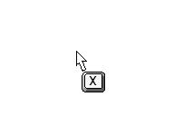
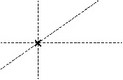
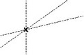
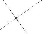
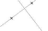
<X>, <P>
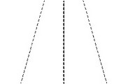
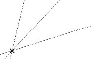
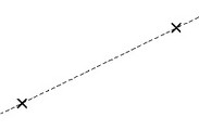
These options are used for creating a set of construction entities in one action, namely, a horizontal line, a vertical line and a node at their intersection.
First type <X>, then <P>.
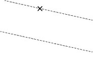
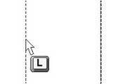
<H>, <P>
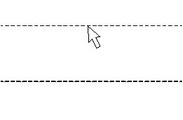
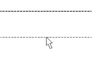
This option sequence creates horizontal lines at a specified distance from the X-axis. Type <H>, and then <P>.
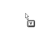
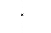
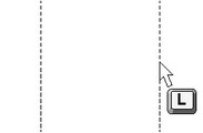
<V>, <P>
This key sequence creates vertical lines at a specified distance from the Y-axis. Type <V>, and then <P>.
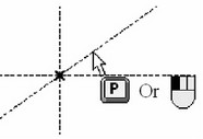
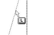
<L>,<P>
This key sequence creates a line, parallel to the selected line at a specified distance. Type <L>, and then <P> for defining the distance from the selected line.
As a rule, this line type is used in drawings most often. This is because the lines on a drawing usually make parallel pairs, with the distance between them being a design parameter.
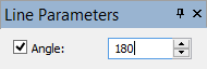
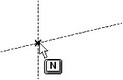
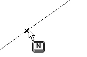
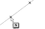
<N>, <P>
This key sequence creates a line at a specified angle to horizontal. Type <N>, and then <P>. The angle is entered in degrees.

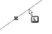
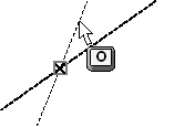
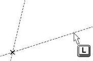
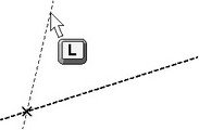
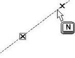
<N>, <L>, <P>
These options define a line passing through a node at a specified angle to a selected line. Move the cursor to the node and type <N>, and then to the line and type <L>. Thereafter, specify the angle between the lines (in degrees).
<N>, <L>, <O>
These options define a line passing through a node and orthogonal angle to a selected line. Move the cursor to the node and type <N>, and then to the line and type <L>. Thereafter, type <O>.
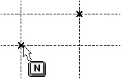
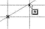
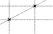
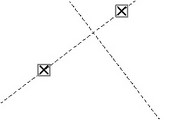
<N>, <N>
This combination defines a line passing through a pair of nodes. Move the cursor to the first node and type <N>. Repeat the same for the second node.
<N>, <H> or <H>, <N>
These option sequences create a horizontal line passing through a node. Move the cursor to the node and type <N>. Next, type <H>. These actions can be reversed.

<N>, <V> or <V>, <N>
These option sequences create a vertical line passing through a node. Move the cursor to the node and type <N>. Next, type <V>. The actions sequence can be reversed.
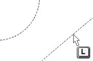
<L>, <N>
This option sequence creates a line parallel to a selected line and passing through a node. Move the cursor to the line and type <L>. Next, move over the node and type <N>.
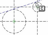
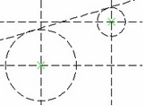
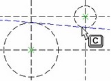
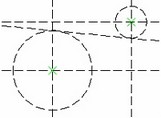
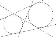
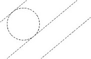
<C>, <C>
This combination defines a line tangent to two circles. Move the cursor to the first one and type <C>, then move to the second and type <C> again. Generally speaking, four distinct lines can be created in this situation, all of which would be two-tangent to the circles.
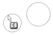
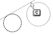

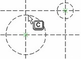
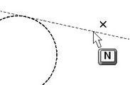
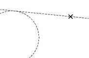
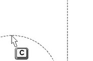
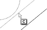
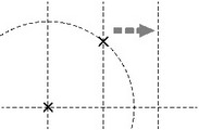
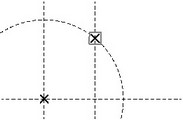
<C>, <N> or <N>, <C>
Using these combinations creates a line tangent to a circle and passing through a node. Move the cursor to the circle and type <C>, then move over the node and type <N>. Two distinct possibilities exist in this situation. One can do selections in the reversed order as well.
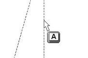
<A>, <L>
Use of such options creates a line (or lines) symmetrical to another one with respect to the selected axis. The symmetry axis is selected by typing the first key, <A>. Then, one can create a single line or multiple lines symmetrical with respect to the axis. A line to be mirrored is selected by typing <L>. Note that after typing <L> key once, the symmetry axis first stays selected, ready for mirroring more lines.
This mode stays active until canceled via <Esc> or ![]() .
.
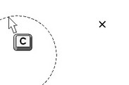
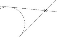
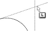
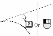
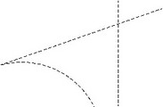
<C>, <L>, <P>
This combination creates a line tangent to a circle and passing at a specified angle to the selected line. Move the cursor to a circle and type <C>, then move over the line and type <L>. You will then see the angle value displayed in the coordinate field of the status bar. This is the angle between the selected and the rubberbanded lines. Now you have a choice of setting the parameter according to the cursor position or edit the parameter by entering a value, variable or expression. In the first case, simply click ![]() , and in the second – use the property window or the parameters dialog box for editing the angle parameter. Note that the angle value is entered in degrees.
, and in the second – use the property window or the parameters dialog box for editing the angle parameter. Note that the angle value is entered in degrees.
<U>, <L>, <L>
Use these options to create a line that is the symmetry axis for the two selected lines. In the case of intersecting lines, turn on the option <U>, move the cursor over one of them and type <L>. Then move over the other line and type <L> once more. A newly created line will bisect the angle between the two lines, acting as the symmetry axis. The same command works on parallel lines as well. After activating the option <U> move the cursor over one line and type <L>, then move over the other and again type <L>. A third parallel line will be created bisecting the distance between the two selected.
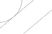
<L>, <C>
These options help define a lane parallel to a selected line and tangent to a circle. Move the cursor over a line and type <L>. Then move over a circle and type <C>. A new line will be created, parallel to the selected line and tangent to the circle.
Note: In this situation, as in some other cases, there are two possibilities for the line placement with respect to the circle. The system distinguishes them and at the creation instance settles with the configuration in which the line is closer to the selection point on the circle.
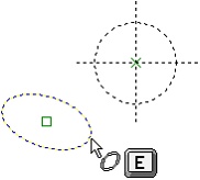
<E>, <C>
The options allow creating the line tangent to an ellipse and a circle at the same time. For constructing the line, bring the cursor to the given ellipse and press <E> (if the object snap mode is on, then it is sufficient just to press ![]() pointing at the ellipse). After that, dynamic image of the created line will end up being tangent to the ellipse for any cursor translations. Then point at the circle and press <C>. Tangency points with an ellipse and a circle (in case of non-uniqueness of the solution) will be selected by the system from the condition of maximum closeness to the cursor location upon selecting the ellipse and the circle.
pointing at the ellipse). After that, dynamic image of the created line will end up being tangent to the ellipse for any cursor translations. Then point at the circle and press <C>. Tangency points with an ellipse and a circle (in case of non-uniqueness of the solution) will be selected by the system from the condition of maximum closeness to the cursor location upon selecting the ellipse and the circle.
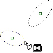
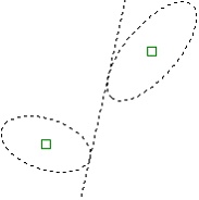
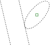
<E>,<E>
With the help of these options the line tangent to two ellipses can be constructed. For constructing the line, point at two ellipses successively: bring the cursor to the first ellipse and press <E>, then repeat the same operations for the second ellipse.
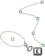
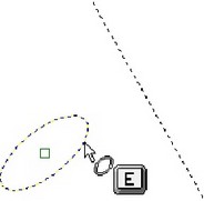
<E>,<S>
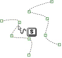
This option sequence allows creating a line tangent simultaneously to an ellipse and a spline. Bring the cursor to the required ellipse and press <E>. Dynamic image of the cursor will become tangent to the selected ellipse. After that, move the cursor to the spline, which a created line should be tangent to, and press <S>.
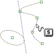
<S>,<S>
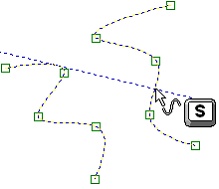
By using the option <S> twice, the line tangent to two splines will be created. For constructing the line, bring the cursor to the first spline and press <S>. Then repeat the same for the second spline. Similar to two previous cases, if different solutions for touching the splines and a created line can be found, tangency points will be selected by the system from the condition of maximum closeness to the cursor location upon selecting the splines.
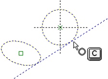
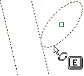
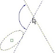
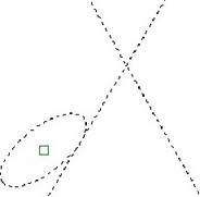
<L>,<E>
This option sequence allows creating the line parallel to another line and tangent to an ellipse. Bring the cursor to the line, which has to be parallel to the new line, and press <L>. Then move the cursor to the ellipse which a created line has to touch and press <E>.
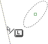
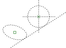
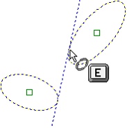
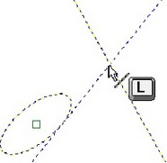
<E>,<L>
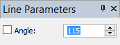
For constructing a line tangent to an ellipse and angular to another line, bring the cursor to the ellipse which the created line has to touch and press <E>. Then point with the cursor at the line at an angle to which the created line has to be drawn, and press <L>. After that, it is necessary to specify the angle between two lines (in degrees) directly in the drawing window or in the properties window.
<T>, <N>, <N>, <P>
This sequence defines a line orthogonal to the imaginary segment spanning two selected nodes. The line is constructed so as to divide the segment in specified proportion. This proportion value is the parameter of the line being created, defined in dimensionless units. For example, with the parameter equal 0, the line will be passing through the first node, with the value 1 – through the second one, while the value 0.5 sets the line through the midpoint between the nodes. Should the nodes change location, the line will adjust, keeping the defined proportion. This kind of construction is used, for example, for drawing a spring with a fixed number of coils and variable length. The distance between the coils of such a spring will vary in a fixed proportion to the total length.
To create this kind of line, in the automenu turn on the option <T>, move the cursor to the first node and type <N>, then over the second node and type <N>. A line starts rubberbanding after the cursor orthogonal to the segment spanning the two selected nodes. The coordinate field will be displaying the current proportion value. Use the property window or the parameters dialog box to specify this value, or simply click ![]() , if satisfied.
, if satisfied.
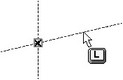
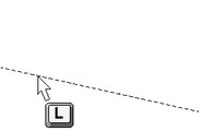
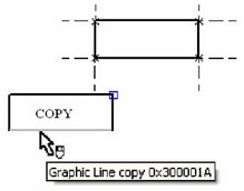
Lines created from 2D projection, 2D fragment, or copy
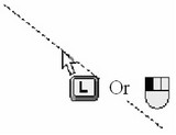
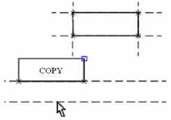
Such lines can be created in object-snapping mode, when the respective flag is set on the "Snap" tab of the "SO: Set System Options" command. Move the cursor to a graphic line that is a part of a 2D projection, 2D fragment or a copy. The line will get pre-highlighted. Click ![]() . A construction line will be created on top of the selected graphic line. Besides, nodes will appear by the end points of the graphic line. Meanwhile, the system will assume the parallel line creation mode.
. A construction line will be created on top of the selected graphic line. Besides, nodes will appear by the end points of the graphic line. Meanwhile, the system will assume the parallel line creation mode.
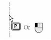
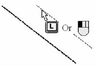
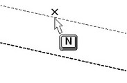
If the object-snapping mode is off, such lines can be created only based on 2D projection lines. To do so, select a desired projection on a drawing using the ![]() option. The selected projection will be highlighted, and the cursor will gain a glyph
option. The selected projection will be highlighted, and the cursor will gain a glyph ![]() . To create a line, simply point the cursor at a line on the projection and click
. To create a line, simply point the cursor at a line on the projection and click ![]() .
.
In this case, the following options will be accessible in the command automenu:
![]() <P> Set Line Parameters
<P> Set Line Parameters
![]() <Esc> Cancel selection
<Esc> Cancel selection
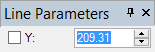
Line parameters
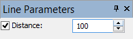
When creating and editing lines, it is often required to define various line parameters. The geometrical parameters, such as coordinates, the distance or the angle to the related line, can be entered in transparent mode in the property window. However, in order to define the general system parameters of the line, one has to use the option ![]() to bring up the dialog box of all line parameters.
to bring up the dialog box of all line parameters.
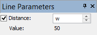
Distance. This is the distance between the newly constructed line and the line selected as the reference for the construction.
Level. Places the line being created on the particular visibility level. Levels help hiding certain elements from display. The level parameter can be assigned a variable.
Layer. This parameter allows placing the line being created on a certain layer.
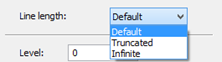
Line length. Defines the way of construction line representation in display. The detailed description of this parameter follows below. The available values of this parameter, provided in the list, are: Default (From Document);
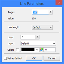
Truncated; Infinite. Color. This parameter defines the color used for displaying the line.
Set as default. Setting this flag means, the current parameter settings in this dialog box will be used from now on in construction line creation, with the exception of the "Distance" parameter.
Truncated lines
Normally, construction line entities appear on a drawing as infinite lines. However, as a drawing grows crowded, managing it becomes difficult. A means is provided for setting shortened representation of construction lines that allows working with lines as segments of limited length.
A trimmed, or truncated, construction line is bound by its two end nodes. The extents of trimmed construction line overhangs can be defined in the command "ST: Set Document Parameters" (the parameter View > Extents).
If a construction line does not have nodes, then it will always appear as an infinite line. If a construction line has only one node then the "Extents" parameter should better be set greater than zero, as otherwise the line will disappear from display.
The line display gets up to date after executing the following options of the "EC: Edit Construction" command:
![]() <T> Update selected Line(s) extents
<T> Update selected Line(s) extents
![]() <Q> Update all Line extents
<Q> Update all Line extents


The function of the "Line length" parameter significantly depends on the settings under the "ST: Set Document Parameters" command, parameter View > Length.
Four ways of line display are supported by the "ST: Set Document Parameters" command:
Default truncated. If a particular line has the parameter "Line length" set to "Default" value, then this line is displayed as a segment.
Default infinite. If a particular line has the parameter "Line length" set to "Default" value, then this line is displayed as an infinite line.
All truncated. Any and all lines will be displayed as segments, regardless of the "Line length" parameter settings.
All infinite. Any and all lines will be displayed as infinite lines.
Another special parameter under the "ST: Set Document Parameters" command is View > Search. It defines the line selection mode. The lines are selected either within the displayed limits or as infinite lines, regardless of other parameter settings.
Using numerical parameters
Entering the "Distance" parameter is a most common case of working with construction line parameters. The positive values of this parameter correspond to locations above the reference horizontal line, while the negative are below, respectively.
In the case of a vertical reference line, the positive values of this parameter are for the left hand-side locations, while the negative are for the right hand-side locations, accordingly.
These rules result from the use of the coordinate system in T-FLEX CAD. That helps keeping the once set relations between construction entities under any modifications of the parameter values.
Note that the "-" sign may be preset by the system before the parameter input box in the property window. The system is monitoring the rubberbanded line position with respect to the reference parallel line. When the new line is rubberbanded in the area of negative offsets, the negative sign is automatically set, and the user needs to enter only the absolute distance.
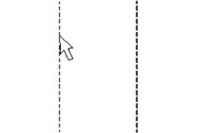
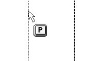
As an alternative to entering a specific distance value, one can use variables. The name of a variable is defined as a US ASCII string of no more than 10 characters. The names are case-sensitive, therefore, for example, the two names "Width" and "width" are different. Let's assign the distance between the two lines a variable "W".
A dialog box will come up then, for defining the value of the variable. The variable being created can be flagged as "External". The variable can have a positive or negative value, or assume the value of another variable or mathematical expression based on other variables. Let's enter the value "50" for the variable. If we flagged the variable as "External", then in future it will be accessible for assigning values from outside the document.
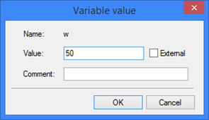
Such situations include, for example, use of external applications, or assigning a value from an assembly document upon inserting the present drawing as a fragment. In our particular example, the variable is not required to be external.
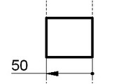
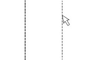
Once the value has been assigned to the variable, a line is created, parallel to the reference one, at the distance of 50 units on the left-hand side of the reference.
Now, one can verify the just defined relation between the lines. Enter the command "V: Edit Variables":
Icon |
Ribbon |
|---|---|
|
Title Block → Additional → Variables |
Keyboard |
Textual Menu |
<V> |
Parameters > Variables |
The Variable editor dialog box will come up on the screen. The only variable displayed in the dialog box will be the just created "W", with the value "50". The Variable editor has four fields (columns): "Name", "Expression", "Value" and "Comment". Since we entered a numerical value for the variable, the "Value" and "Expression" readings are the same.
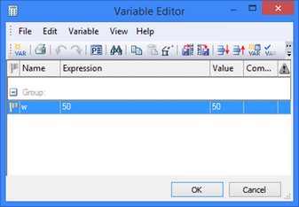
The quantity in the "Expression" field can be modified as necessary. After that, exit the editor by pressing [OK]. The drawing will instantly update per the new value of the "W" variable. An expression can be used for the parameter "Distance" just in the same way. For example, suppose, the new line is constructed on the right-hand side of the vertical line. Then, to work around the "-" sign in the value of the variable, the variable can be assigned the expression “-W”. Generally speaking, one can use formulas with several variables in the expressions.
For viewing and editing the values of the variables, one can use an additional window “Variables” which allows working with variables in transparent mode.
Editing lines
The "EC: Edit Construction" command is provided for editing construction lines. It is one of most often used commands. This is the command that supports creation of new drawing configurations by providing a dialog box for varying necessary construction parameters. The command allows editing all kinds of construction entities.
The command is called as:
Icon |
Ribbon |
|---|---|
|
Draw → Additional → 2D Construction |
Keyboard |
Textual Menu |
<EC> |
Edit > 2D Construction |
To modify location of some construction entity, simply select it using ![]() , move the cursor over the desired location, and click
, move the cursor over the desired location, and click ![]() again. To specify the exact value of the placement parameter, use the property window or the parameters dialog box via the
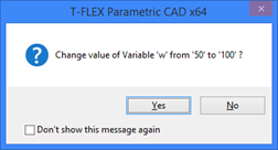
again. To specify the exact value of the placement parameter, use the property window or the parameters dialog box via the ![]() option. If the entity was driven by a variable, the system will output a warning.
option. If the entity was driven by a variable, the system will output a warning.
To avoid the system warnings, call the option ![]() before selecting any entities. A dialog box will come up, in which the item "Auto change Variables" needs to be checked.
before selecting any entities. A dialog box will come up, in which the item "Auto change Variables" needs to be checked.
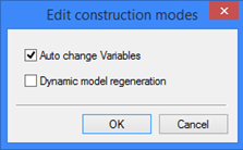
When modifying the values of construction parameters it is possible to use Relations that appear on element selection. These Relations are temporary. They will automatically disappear on editing finish. To modify the values of construction parameters with the help of Relations it is necessary to turn off “Dynamic recalculation” mode (option ![]() , see below).
, see below).
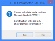
It is possible that some construction entity can't be recreated after modifying parameter values due to geometrical incompatibilities among the entities. In such a case, the system will output an error message and specify the particular failing relation.
The selected line is highlighted on the drawing. Besides, other construction entities are highlighted that were used as references for the line creation. The following options are available in the command "EC: Edit Construction":
|
<> |
Dynamic model regeneration mode |
|
<P> |
Set command options |
|
<O> |
Create Name for selected Element |
|
<M> |
Modify Construction Line relations |
|
<T> |
Update selected Line(s) extents |
|
<Q> |
Update all Line extents |
|
<K> |
Break link with variable |
|
<I> |
Select Other Element |
|
<R> |
Select element from list |
|
<*> |
Select All Elements |
|
<Del> |
Delete selected Element(s) |
|
<Esc> |
Cancel selection |
<Shift><Enter> |
Add Construction Element to Selected for Editing |
|
<Ctrl><Enter> |
Exclude Construction Element from Selected List |
|
The option ![]() (<K>) allows switching all parameters of the selected construction line from dependency on variables to the constant values.
(<K>) allows switching all parameters of the selected construction line from dependency on variables to the constant values.
The option <O> allows specifying names for construction lines in order to define advanced parametric dependencies. Such a name will help exactly identify a construction line and, in particular, directly access certain proprietary data of the line in the variable editor via the command "V: Edit Variables", using the function "get". The name is not required for common situations of parametric design.
Modifying relations between construction lines
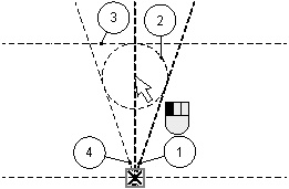
If for some reason you would like to modify the existing relations between the construction lines, this can be easily done using the ![]() option. Let's review an example of using this option. The line 1 is created at a given angle to a vertical line. Besides, it is passing through a node at the intersection of the vertical and a horizontal line. The circle 2 was constructed tangent to the lines 1 and 4, while the line 3 tangent to the circle 2.
option. Let's review an example of using this option. The line 1 is created at a given angle to a vertical line. Besides, it is passing through a node at the intersection of the vertical and a horizontal line. The circle 2 was constructed tangent to the lines 1 and 4, while the line 3 tangent to the circle 2.
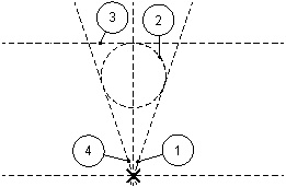
Suppose, you would like to make the line 1 parallel to the vertical line. Since other construction entities are created using the former line as a reference, the line may not be simply deleted and then differently created anew. The deletion of this line would require also removing the line 3, followed by removal of the circle 2. This is exactly the case when the option <M> is to be used. Enter the command "EC: Edit Construction" and select the line 1 for editing. This line will get highlighted along with another line and the node used as references for this line creation.
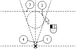
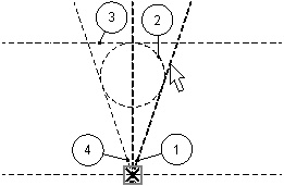
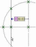
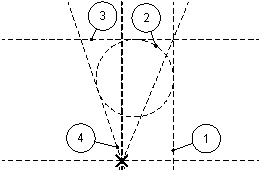
After selecting the line, type <M> for modifying the definition of the line 1 construction. Note that the system brought you into the construction line creation command, "L: Construct Line". Now you can create this line as if anew. The difference from constructing a line without using the <M> option is that both the line being modified and the reference line are both highlighted on the screen. Select a line - the reference for the line 1 to be parallel to. Then rubberband the new line to the desired distance from the reference and fix that location by clicking ![]() .
.
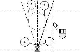
Line 1 will appear in the new position, while all the rest of entities using the line as a reference will keep their relations with the line, as, for instance, the circle 2 will remain tangent to the line 1. The only restriction on modifying relations between construction lines is a ban on recursive definition, that is, the line may not reference itself. Should this occur, a message will be displayed about recursion, and the modification will be cancelled. With this exception, any relations between lines and circles may be modified at any time. This functionality is especially useful on importing drawings from other systems, such as, for example, *.DXF or *.DWG files of the AutoCAD system.
Deleting construction lines
To delete a construction line, simply select the line using ![]() and call the <Del> option. If the line is not referenced by any other drawing elements, it will be deleted. Should there be other elements defined based on the selected line, a warning will appear about deletion of all elements related with the line.
and call the <Del> option. If the line is not referenced by any other drawing elements, it will be deleted. Should there be other elements defined based on the selected line, a warning will appear about deletion of all elements related with the line.