Circles |
  
|
Circles |
|
Circles in T-FLEX CAD are constructed similarly to lines, that is, by defining their geometrical relations with other construction entities. Examples of such relations include placement of the circle center at a node, tangency to a line, tangency to a circle, passing through a node, concentricity with another circle, symmetry to another circle.
The T-FLEX CAD circles can be divided into two main groups:
- circles, whose radius can be assigned a number (for example, a circle with the center placed at a node, or a circle tangent to two non-parallel lines);
- circles, whose placement and radius are defined by construction (for example, a circle passing through three given nodes).
If a circle has a numerical parameter (the radius), then the parameter can be defined by a constant, a variable or an expression. To assign the numerical parameter, one can use the property window. The circles are created in the command "C: Construct Circle". The relations defined at the time of circle construction can be modified in the command "EC: Edit Construction" in a similar to line way of handling.
Circle construction examples
Before discussing all capabilities of the command "C: Construct Circle", let's consider examples of constructing most common types of circles. Additionally, the command "L: Construct Line" will be used in constructions. This command was described in the previous chapter.
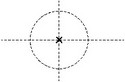
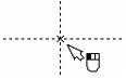
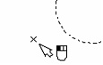
Enter the command "L: Construct Line". Select the option <X>, represented in the automenu by the icon ![]() . Move the cursor over the center of the graphic window and click
. Move the cursor over the center of the graphic window and click ![]() . This creates two lines, a vertical and a horizontal one, and a node at the intersection. After that, enter the command "C: Construct Circle".
. This creates two lines, a vertical and a horizontal one, and a node at the intersection. After that, enter the command "C: Construct Circle".
Icon |
Ribbon |
|---|---|
|
Draw → Construct → Circle |
Keyboard |
Textual Menu |
<C> |
Construct > Circle |
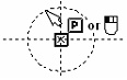
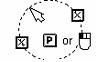
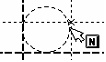
Move the cursor to the just created node and click ![]() . Thus you define the circle center. Internally, the system stores the relation between the circle center and the node. The node will be highlighted, and a circle will start rubberbanding after the cursor. Meanwhile, the radius of this circle will be dynamically updating on the status bar ("R=..."). Clicking
. Thus you define the circle center. Internally, the system stores the relation between the circle center and the node. The node will be highlighted, and a circle will start rubberbanding after the cursor. Meanwhile, the radius of this circle will be dynamically updating on the status bar ("R=..."). Clicking ![]() completes construction of the circle with the current radius.
completes construction of the circle with the current radius.
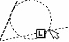
For a simple way of defining an exact value of the circle radius while rubberbanding, use the property window in transparent mode. Besides, one can call a dialog box with the complete set of circle parameters via the ![]() option of the automenu. The parameters dialog box allows defining, besides the radius, the circle's general system parameters, such as visibility level, layer and color. For instance, the default drawing settings of visibility are such that construction entities with the level defined in the range 0-127 are visible (see the command "SH: Set Levels"). This means, changing the level value of the circle being created to "-1", will hide the circle from display, as the level value is not in the range 0-127. For already created circles, in command waiting mode point the cursor at the circle and double-click
option of the automenu. The parameters dialog box allows defining, besides the radius, the circle's general system parameters, such as visibility level, layer and color. For instance, the default drawing settings of visibility are such that construction entities with the level defined in the range 0-127 are visible (see the command "SH: Set Levels"). This means, changing the level value of the circle being created to "-1", will hide the circle from display, as the level value is not in the range 0-127. For already created circles, in command waiting mode point the cursor at the circle and double-click ![]() . The circle parameters dialog box will appear on the screen. Change the level value to "-1" and press [OK] to confirm the input. Note that the circle disappeared from display. However, this does not mean that the circle is completely removed from the model Move the cursor to the location where the circle used to be, and once again click
. The circle parameters dialog box will appear on the screen. Change the level value to "-1" and press [OK] to confirm the input. Note that the circle disappeared from display. However, this does not mean that the circle is completely removed from the model Move the cursor to the location where the circle used to be, and once again click ![]() . The circle will be selected, in spite of being invisible. Call the parameters dialog box again and set a different value for the visibility level, for example, "0" (zero). Now, as you press [OK], the circle becomes visible again.
. The circle will be selected, in spite of being invisible. Call the parameters dialog box again and set a different value for the visibility level, for example, "0" (zero). Now, as you press [OK], the circle becomes visible again.
Note: to actually make the hidden drawing elements unselectable, set the appropriate value for the parameter View > Element selection" in the ST: Set Document Parameters command.
Another way of making a circle invisible is by using layers. Place the circle on a certain layer, and then set the layer invisible in the command "QL: Configure Layers". To place the circle on a layer, enter the layer name either in the "Layer" entry of the circle parameters dialog box, or in the respective field of the system toolbar.
Another type of a circle often used in base geometry construction is a circle tangent to two lines. In order to try creating this type of a circle, begin again with the "C: Construct Circle" command.
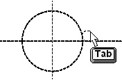
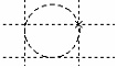
First, move the cursor over the vertical line that already exists on the drawing, and type <L>. The line will get highlighted, and the cursor will start rubberbanding a circle locked tangent to the selected line. Now move the cursor over the horizontal line and once again type <L>. The second line will be selected, and the rubberbanded circle will now be tangent to two lines.
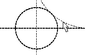
The dynamically changing circle radius will be displayed in the coordinate field of the status bar. Note that you can move the cursor to any of the four quadrants defined by the lines, and the rubberbanded circle will correctly follow the cursor.

Now, you can set the circle radius by simply clicking ![]() , or by inputting in the property window or the circle parameters dialog box (<P>). It is also possible to snap the circle to a 2D node with the help of the
, or by inputting in the property window or the circle parameters dialog box (<P>). It is also possible to snap the circle to a 2D node with the help of the ![]() option of the automenu (<G> “Specify snapping to a node”). The snapped circle will always be positioned in such a way that the distance to the indicated node is minimal. Thus, it is possible to specify the required location of the circle with respect to original lines.
option of the automenu (<G> “Specify snapping to a node”). The snapped circle will always be positioned in such a way that the distance to the indicated node is minimal. Thus, it is possible to specify the required location of the circle with respect to original lines.
Once the circle is created tangent to two lines, this relation will always be maintained. To witness this, do, for example, the following. Exit the command "C: Construct Circle". In command-waiting mode, move the cursor over the created circle and click ![]() . The system will enter the editing command ("EC: Edit Construction"). The circle will be highlighted. Now the user can easily modify its radius by moving the cursor. Meanwhile, the tangency to the lines will be maintained. Try doing this several times, moving the circle over other quadrants.
. The system will enter the editing command ("EC: Edit Construction"). The circle will be highlighted. Now the user can easily modify its radius by moving the cursor. Meanwhile, the tangency to the lines will be maintained. Try doing this several times, moving the circle over other quadrants.
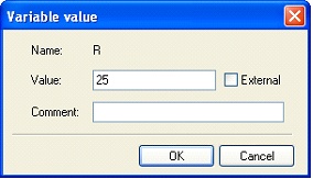
At any moment while rubberbanding the circle in the command "EC: Edit Construction", one can modify the parameter value (the radius). This can be done in transparent mode in the property window, or in the parameters dialog (the option ![]() ) Instead of a numerical value, a variable name or an expression can be used. For example, instead of the radius value, one can enter a variable name "R". After pressing [OK] the system will request the value for the newly created variable "R". One can accept the system default value or modify it as desired. In future, this will allow using the variable for data exchange with external applications or for configuring the drawing when inserting into an assembly. Upon confirming the value of the new variable, the drawing will be regenerated per the entered radius value.
) Instead of a numerical value, a variable name or an expression can be used. For example, instead of the radius value, one can enter a variable name "R". After pressing [OK] the system will request the value for the newly created variable "R". One can accept the system default value or modify it as desired. In future, this will allow using the variable for data exchange with external applications or for configuring the drawing when inserting into an assembly. Upon confirming the value of the new variable, the drawing will be regenerated per the entered radius value.
From now on, the circle radius is driven by the variable "R". The value of this variable can be easily modified in the command "V: Edit Variables". Call the command "V: Edit Variables".
Icon |
Ribbon |
|---|---|
|
Title Block → Additional → Variables |
Keyboard |
Textual Menu |
<V> |
Parameters > Variables |
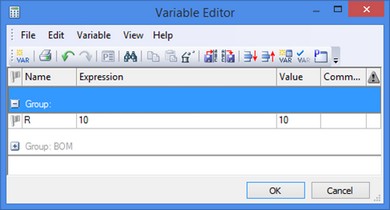
The variable editor window will come on the screen (see the chapter "Variables"), containing four columns: "Name", "Expression", "Value", "Comment". The "Name" entry contains the only existing variable, the "R". The "Expression" entry displays the number defined at variable creation. The same number is displayed in the "Value" field. Let's change the value of this variable. Enter a new value, say, "50". Upon confirming the input by <Enter>, the new value will be displayed in the third column, titled "Value".
The "Comment" field may be used for entering information text about the current variable. This information is called "the variable comment". The comment is not used in defining geometrical relations or regeneration per se, however, it may be quite helpful to the user at the time of modifying the drawing.
Modify the "R" variable several times, exiting the variable editor each time by pressing [OK]. The drawing will regenerate each time according to the new entered value of the variable.
Constructing circles
The command "C: Construct Circle" provides various options from the following list, depending on the current state:
|
<Enter> |
Select a node as the circle center |
|
<P> |
Set circle parameters |
|
<L> |
Select tangent line |
|
<N> |
Select a node for the circle to pass through |
|
<C> |
Select tangent circle |
|
<E> |
Select tangent ellipse |
|
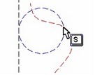
<S> |
Select tangent spline |
|
<A> |
Select symmetry axis (line) to mirror the circle. |
|
<O> |
Select concentric circle |
|
<W> |
Select 2D projection |
|
<Z> |
Change construction tangency |
|
<Space> |
Construct a node at the nearest intersection of two construction entities |
|
<F4> |
Execute Edit Construction command |
|
<Esc> |
Cancel selection |
|
<Esc> |
Exit command |
T-FLEX CAD supports the most common circle construction modes, which are:
- constructing a circle with the center at a selected node
- constructing a circle passing through a selected node
The following options initiate these modes:
![]() <T> Select a node as the center of the circle
<T> Select a node as the center of the circle
![]() <T> Select a node for the circle to pass through
<T> Select a node for the circle to pass through
Upon calling the command, one of the modes is activated by default, as indicated by the pushed icon in the automenu.
Just as with the construction lines, various combinations of a small set of options with a specific circle construction mode yield a variety of geometrical dependency sets in the constructed circles:
<Enter>, <P> Circle with center at a node, with a specified radius <*>
<Enter>, <С> Circle with center at a node, tangent to a circle
<Enter>, <L> Circle with center at a node, tangent to a line
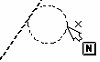
<Enter>, <N> Circle with center in the nearest node, passing through a node
<L>,<L>,<P> Circle tangent to two lines, with a specified radius <*>
<N>,<L>,<P> Circle tangent to a line, passing through a node, with a specified radius <*> <**>
<N>,<C>,<P> Circle tangent to a circle, passing through a node, with a specified radius <*> <**>
<N>,<N>,<P> Circle passing through two nodes, with a specified radius <*> <**>
<C>,<L>,<P> Circle tangent to a line and a circle, with a specified radius <*> <**>
<C>,<C>,<P> Circle tangent to two circles, with a specified radius <*>
<N>,<N>,<N> Circle passing through three nodes
<L>,<L>,<L> Circle tangent to three lines
<N>,<L>,<L> Circle tangent to two lines, passing through a node <**>
<C>,<L>,<L> Circle tangent to two lines and a circle <**>
<C>,<C>,<N> Circle tangent to two circles, passing through a node <**>
<C>,<L>,<N> Circle tangent to a circle and a line, passing through a node <**>
<N>,<N>,<L> Circle tangent to a line, passing through two nodes <**>
<N>,<N>,<C> Circle tangent to a circle, passing through two nodes <**>
<L>,<S> <L>,<E> Circle tangent to a line and a spline or ellipse <**>
<C>,<S> <C>,<E> Circle tangent to a circle and a spline or ellipse <**>
<S>,<S> Circle tangent to two splines
<E>,<E> Circle tangent to two ellipses
<S>,<E> Circle tangent to a spline and an ellipse <**>
<O>,<P> Circle, concentric with another circle, with a specified radial offset
<A>,<C> A circle mirrored about a symmetry axis
<*> - Use of <P> equivalent to <Enter> or ![]() .
.
<**> - The options <C>,<L>,<N>,<S>,<E> can be used in any order, besides the listed.
In both circle construction and editing, typing <Z> can be conveniently used for traversing configurations within the chosen type of circle construction. For example, two configurations are possible when constructing a circle tangent to a line and another circle, with the same cursor position. The <Z> key can be used for switching between these two configurations.
Similarly, during editing, a circle configuration can be flipped as well.
When creating circles tangent to two elements (two lines, line and circle, two circles), the options used for creation and cancellation of snapping to a node are available in the automenu:
|
<G> |
Apply snapping to a node |
|
<B> |
Cancel snapping to a node |
The ![]() option is used for snapping circles tangent to two construction lines to an additional node that will determine the circle’s tangency choice. After this option is invoked you need to specify the required node with the help of
option is used for snapping circles tangent to two construction lines to an additional node that will determine the circle’s tangency choice. After this option is invoked you need to specify the required node with the help of ![]() . As a result of applying this option, upon change in the drawing the circle will be reconstructed in such a way that its location is as close as possible to the node. This allows us to uniquely specify location of the circle with respect to the original lines.
. As a result of applying this option, upon change in the drawing the circle will be reconstructed in such a way that its location is as close as possible to the node. This allows us to uniquely specify location of the circle with respect to the original lines.
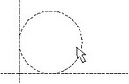
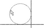
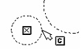
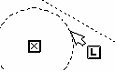
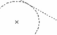
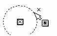
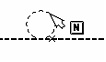
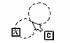
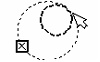
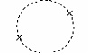
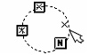
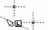
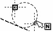
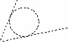
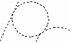
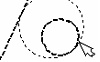
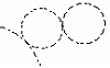
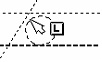
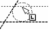
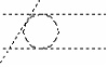
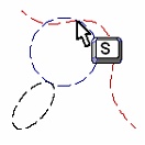
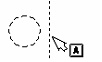
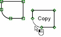
Example given below shows us how this capability can be used. Location of straight lines on the drawing with respect to the line-symmetry axis is controlled by the value of the variable K. Two circles are constructed as tangent to two lines. In addition, the circle that is shown with a solid line is snapped to the indicated node. The snapping node is not specified for the second circle. The first figure shows the initial location of the drawing’s elements (K=1).
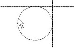
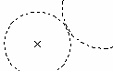
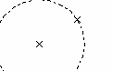
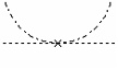
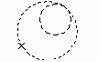
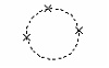
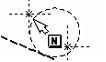
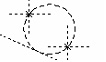
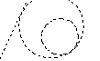
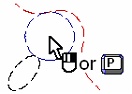
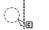
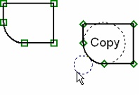
The second figure shows how the drawing will be changed when the variable’s value is К=-1. The circle that was snapped to the node was reconstructed correctly. The second circle that is constructed without spanning to a node changed its location with respect to the symmetry axis.
If it is necessary to cancel or reselect the snapping node, use the ![]() option.
option.
Let's review each way of constructing circles in details.
Various ways of constructing circles
Begin with setting the option:
![]() <T> Select a node as the circle center
<T> Select a node as the circle center
<Enter>, <P>
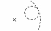
This combination creates a circle with the center in the selected node and the radius defined by either placing the cursor and clicking ![]() or entering an exact value in the property window or parameters dialog box (the option <P>). To create this type of a circle, point the cursor at the desired node and click
or entering an exact value in the property window or parameters dialog box (the option <P>). To create this type of a circle, point the cursor at the desired node and click ![]() . The node will be highlighted, and a circle with the center in this node will start rubberbanding. The circle can then be fixed manually, by clicking
. The node will be highlighted, and a circle with the center in this node will start rubberbanding. The circle can then be fixed manually, by clicking ![]() , or exactly, by specifying the radius value in the property window or parameters dialog box.
, or exactly, by specifying the radius value in the property window or parameters dialog box.
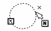
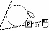
<Enter>, <N>
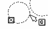
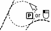
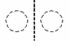
This combination creates a circle with the center at a specified node, and tangent to another circle. Move the cursor to an existing node or use the <Space> option for creating a node at the nearest intersection of construction entities. Click ![]() . This results in rubberbanding a circle with the center in the selected node. Move the cursor to a circle to become the tangency reference for the one being created, and type <C>. The required circle will be created. Two different configurations are possible, depending on where on the tangent circle the cursor was pointing at the time of entering the <N> option.
. This results in rubberbanding a circle with the center in the selected node. Move the cursor to a circle to become the tangency reference for the one being created, and type <C>. The required circle will be created. Two different configurations are possible, depending on where on the tangent circle the cursor was pointing at the time of entering the <N> option.
 or
or 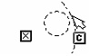
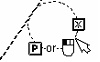
<Enter>, <L>
This combination creates a circle with the center at a node, tangent to a construction line. Move the cursor to an existing node or use the <Space> option for creating a node at the nearest intersection. Click ![]() . A circle will start rubberbanding with the center in the selected node. Move the cursor over the line to become the tangency reference for the circle, and type <L>. The required circle will be created.
. A circle will start rubberbanding with the center in the selected node. Move the cursor over the line to become the tangency reference for the circle, and type <L>. The required circle will be created.
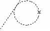
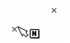
<Enter>, <N>
This combination creates a circle with the center at a node, passing through another node. Move the cursor to an existing node or use the <Space> option for creating a node at the nearest intersection. Click ![]() . This allows you to rubberband a circle with the center in the selected node. Move the cursor to the node for the circle to pass through, and type <N> or
. This allows you to rubberband a circle with the center in the selected node. Move the cursor to the node for the circle to pass through, and type <N> or ![]() . The required circle will be created.
. The required circle will be created.
<L>, <N>, <P> for use in the mode of constructing a circle with the center at a node.
<N>, <L>, <P> for use in the mode of constructing a circle passing through a node.
Either of the two option combinations creates a circle of a specified radius, tangent to a line and passing through a node. Subsequently select a line and a node, using the options <L> and <N> respectively. Then specify the radius either by a click ![]() or by inputting the exact value in the property window or parameters dialog box (the option <P>).
or by inputting the exact value in the property window or parameters dialog box (the option <P>).
Please note that the node may belong to the line, which is often the case in drawings.
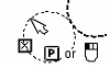
<C>, <N>, <P> for use in the mode of constructing a circle with the center at a node.
<N>, <C>, <P> for use in the mode of constructing a circle passing through a node.
Either of the two option combinations creates a circle of a specified radius, tangent to a circle and passing through a node. Subsequently select a circle and a node, using the options <N> and <N> respectively. Then specify the radius either by a click ![]() or by inputting the exact value in the property window or parameters dialog box. Please note that different configurations are possible, depending on where on the entities the cursor was pointing at the selection time.
or by inputting the exact value in the property window or parameters dialog box. Please note that different configurations are possible, depending on where on the entities the cursor was pointing at the selection time.
Now set the option:
![]() <T> Select a node for the circle to pass through
<T> Select a node for the circle to pass through
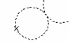
<N>, <N>, <P>
This combination creates a circle of a specified radius, passing through two nodes. Move the cursor over the first node and type <N>. Repeat for the second node. Then define the circle radius. Do this by specifying approximately by clicking ![]() or exactly in the property window or parameters dialog box (the option <P>).
or exactly in the property window or parameters dialog box (the option <P>).
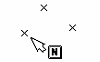
<N>, <N>, <N>
This combination creates a circle passing through three nodes. Move the cursor over the first node and type <N>. Repeat for the second and third node.
<L>, <L>, <N> for use in the mode of constructing a circle with the center at a node.
<N>, <L>, <L> for use in the mode of constructing a circle passing through a node.
This combination creates a circle tangent to two lines and passing through a node. Move the cursor over the first line and type <L>. Repeat for the second line. Then specify the node via <N>. Note that the order of typing the option keys may vary.
<L>, <N>, <N> for use in the mode of constructing a circle with the center at a node.
<N>, <L>, <N> for use in the mode of constructing a circle passing through a node.
<N>, <N>, <L> for use in the mode of constructing a circle passing through a node.
This combination creates a circle tangent to a line and passing through two nodes. Move the cursor over the line and type <L>. Then use the option <N> twice for selecting the nodes. Note that the order of typing the option keys may vary.
Regardless of what construction mode the system is in, the circles can also be created in the following ways:
<L>, <L>, <P>
This combination creates a circle of a specified radius, tangent to two non-parallel lines. To create a circle, move the cursor over the first construction line and type <L>. Repeat for the second line. Then define the circle radius either by clicking ![]() or by inputting in the property window or parameters dialog box (the option <P>). Four various configurations are possible.
or by inputting in the property window or parameters dialog box (the option <P>). Four various configurations are possible.
Location of a circle can be made more precise by snapping to a node with the help of the ![]() option.
option.
<L>, <N>, <P>
<N>, <L>, <P>
Either of the two option combinations creates a circle of a specified radius, tangent to a line and a circle. Subsequently select a line and a circle, using the options <L> and <N> respectively. Then specify the radius either by clicking ![]() or by inputting in the property window or parameters dialog box (the option <P>). Various tangency configurations are possible.
or by inputting in the property window or parameters dialog box (the option <P>). Various tangency configurations are possible.
Location of a circle can be made more precise by snapping to a node with the help of the ![]() option.
option.
<N>, <N>, <P>
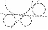
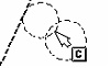
This combination creates a circle of a specified radius, tangent to two circles. Move the cursor over the first circle and type <С>. Repeat for the second circle. Then specify the radius – approximately, by clicking ![]() , or exactly, by inputting in the property window or parameters dialog box (the option <P>). This type of circle construction is most plentiful in resulting circle configurations. Getting the desired one among various tangency types is done by appropriately positioning the cursor when selecting. In some cases, as, for instance, in the case of a surrounding circle, an appropriate selection gets easier when zoomed well out with the command "ZW: Zoom Window".
, or exactly, by inputting in the property window or parameters dialog box (the option <P>). This type of circle construction is most plentiful in resulting circle configurations. Getting the desired one among various tangency types is done by appropriately positioning the cursor when selecting. In some cases, as, for instance, in the case of a surrounding circle, an appropriate selection gets easier when zoomed well out with the command "ZW: Zoom Window".

Location of a circle can be made more precise by snapping to a node with the help of the ![]() option.
option.
<L>, <L>, <L>
This combination creates a circle tangent to three lines. Move the cursor over the first line and type <L>. Repeat for the second and the third line. When selecting the lines, pay attention to the cursor position, which should be on the side of line intended for the circle location.
<L>, <S>, <P> or <S>, <L>, <P> for constructing a circle tangent to a line and a spline.
<L>, <E>, <P> or <E>, <L>, <P> for constructing a circle tangent to a line and an ellipse.
This combination creates a circle tangent to a line and a spline or an ellipse. Subsequently select a line and a spline (ellipse), using the options <L> and <S> (<E>) respectively. Then specify the radius either by a click ![]() or by inputting in the property window or parameters dialog box (the option <P>).
or by inputting in the property window or parameters dialog box (the option <P>).
<C>,<S>,<P> or <S>,<C>,<P> for constructing a circle tangent to a circle and a spline.
<C>,<E>,<P> or <E>,<C>,<P> for constructing a circle tangent to a circle and an ellipse.
This combination creates a circle tangent to another circle and a spline or an ellipse. Subsequently select a circle and a spline (ellipse), using the options <C> and <S> (<E>) respectively. Then specify the radius either by a click ![]() or by inputting in the property window or parameters dialog box (the option <P>).
or by inputting in the property window or parameters dialog box (the option <P>).

<S>,<E>,<P> or <E>,<S>,<P> for constructing a circle tangent to a spline and an ellipse.
<S>,<S>,<P> for constructing a circle tangent to two splines.
<E>,<E>,<P> for constructing a circle tangent to two ellipses.
This combination creates a circle, tangent to two splines or ellipses. Subsequently select the intended entities, spline(s) and/or ellipse(s), using the options <S> and/or <E>. Then specify the radius either by clicking ![]() or by inputting in the property window or parameters dialog box (the option <P>).
or by inputting in the property window or parameters dialog box (the option <P>).
<O>, <P>
This combination creates a circle, concentric to a selected one, with the specified radius offset. Move the cursor over a circle and type <O>. Then define the radius offset by a click ![]() , or by an input in the property window or circle parameters dialog box (the option <P>).
, or by an input in the property window or circle parameters dialog box (the option <P>).
The offset is considered negative for the circles within, positive for the ones outside the defining circle.
<A>, <C>
This combination creates a circle, mirrored from another circle about a straight line. To select the symmetry axis, move the cursor over a line and type <A>. Then select a circle using <С>.
Circles constructed based on 2D projection, 2D fragment or copy
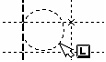
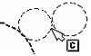
Such circles can be created in the object snapping mode, if the respective flag is set in the command "SO: Set System Options" on the "Snap" tab. Move the cursor over a graphic entity – a circle or an arc on a 2D projection, 2D fragment or a copy. The entity will be pre-highlighted. Clicking ![]() at that moment creates a circle based on the selected entity.
at that moment creates a circle based on the selected entity.
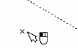
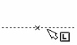
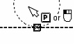
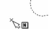
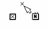
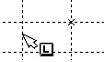
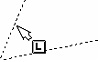
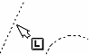
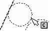
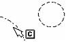
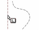
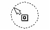
If the object-snapping mode is off, then circles can be created based on 2D projection entities only. To do so, use the option ![]() and select the desired projection on the drawing. The selected projection will be highlighted, and the cursor will gain the glyph
and select the desired projection on the drawing. The selected projection will be highlighted, and the cursor will gain the glyph ![]() . Now, to create a circle, simply point the cursor at a projection entity – arc or circle - and click
. Now, to create a circle, simply point the cursor at a projection entity – arc or circle - and click ![]() .
.
The following options will then become available in the automenu:
![]() <P> Set Circle parameters
<P> Set Circle parameters
![]() <Esc> Cancel selection
<Esc> Cancel selection
Circle parameters
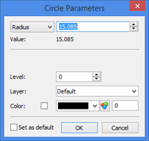
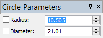
Various parameters need to be defined when creating or editing circles. The geometrical parameters – the radius or the offset for concentric circles can be defined in the transparent mode via the property window. However, the general system parameters can only be accessed via the ![]() option that provides access to all circle parameters via a dialog box.
option that provides access to all circle parameters via a dialog box.
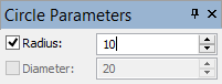
Radius. Defines the circle radius. Allows numerical value, variable or expression input.
Level. Places the circle being created on a certain visibility level, used for hiding certain elements from display when necessary.
Layer. Is used for linking the circle being created to a certain layer.
Color. This parameter defines the color of displaying the circle on the screen.
Set as default. When this flag is set, the parameters defined in this dialog box will be used in creation of new construction entities (except the "Radius" parameter).