Variables |
  
|
Variables |
|
This chapter describes the uses of variables in T-FLEX CAD, the ways of defining parametric relations between the drawing elements and the idea of parameterization without programming. The variables allow extending the concept of parameterization on a deeper level. This chapter describes how to perform complex mathematical calculations within a drawing, how to define relations between construction entities, and other very useful capabilities of the system.
Main concepts
The T-FLEX CAD variables – are auxiliary elements of the system which enable to specify different types of non-geometrical interconnections between the elements of a drawing.
For example, the variables can serve as parameters of construction lines. In this case, the value of the construction line parameter will be determined by the value of the variable. If the value of the variable changes, then the value of the construction line parameter connected to it will be automatically modified (for example, radius of a circle or line location). With the help of variables, it is possible to assign color or visibility of the elements of a drawing, parameters of hatches, the text content, various parameters, etc. The variables can be also used upon creating a 3D model.
By assigning interconnections between the values of the variables, which determine parameters of the drawing's construction elements and drawing's image elements, it is possible to achieve automatic modification of the entire drawing when changes in the values of one or several basic variables are made.
Creating Variables
T-FLEX CAD system provides various ways of creating variables:
●using variable editor;
●while creating and editing construction line parameters and also other elements of the drawing or 3D model;
●using text editor;
●while defining textual strings for parameters of certain elements;
●while defining practically any of the numerical parameters of the system elements (levels, priorities, etc.)
The main tool for handling variables is the variable editor. It allows a user to perform any manipulations over the variables. Thus, we will commence describing the work with the variables exactly with the description of the variables editor. All other methods for creating variables will be described later, in the section “Using variables in the TFLEX CAD”.
Variables Characteristics
Before getting to description of the variables editor itself and how to work in it, let's consider the main characteristics of any variable of the T-FLEX CAD.
Upon creating any variable of the T-FLEX CAD, it is necessary to indicate:
-a unique name of the given variable which enables to uniquely identify it in the document and also determine the type of the given variable (text or real);
-expression, based on which the system will calculate the current value of the variable.
Moreover, there is also a number of additional characteristics of variables, which can be specified in case of need. Several of them enable to impart additional properties to the variables (for example, the indication of external variable). Others are used exclusively for simplifying the work with a large number of variables in the document (comment of variable, group of variable).
Rules for assigning variables' names
The name of any T-FLEX CAD variable must represent itself a string of characters. The letters, numbers and the character “_” (underlining) can be used in the name. There is no limitation on the length of the variable's name.
The variable's name determines the type of the variable: real or text. The type of the variable shows what sort of values the given variable may take. The type is determined by the first character in the name of the variable. The name of the real variable must start with the letter, text variable – with the symbol $.
Examples of correct variable names:
VAR1; VVVVVVVVVV; VAR_1; $TEXT; WIDTH; width;
Note that the two last variable names are considered different, as the names are case-sensitive. Local language extensions of US ASCII are supported for the names. Local language users shall keep in mind that some language characters (particularly, Cyrillic and Greek) resemble the standard US ASCII, while their system codes may be different. Therefore, care should be taken in entering names, as the system will not recognize a name with the same appearance yet actually composed of different characters.
Examples of inappropriate variable names:
1_VAR (the first character is not a letter);
!_VAR! (inadmissible “!” character is used);
V A R (the name may not contain “space” characters).
Expression for variable
An expression is specified for each variable so that the system could calculate the value of the variable at any moment of time. An expression – is a mathematical formula, containing standard algebraic operations, logical operations, conditional operations, calls to mathematical functions and the T-FLEX CAD functions, various constants (real or character, depending on the type of variable), the values of other variables. As a result of the expression calculation, the value of the variable is obtained.
The rules for composing expressions for the T-FLEX CAD variables and description of the functions that can be used inside the expressions are described in chapter "Functions for Working with Variables".
Upon specifying the expression for the variable, the type of the variables should be taken into account. Real variables can take only numeric values (12; 125; -234; 781.234; 3.834e+6), text variables – only character values (“Text”; “String”; “Name”).
An expression can represent itself just a constant (numeric or character depending on the type of variable).
Variables-functions
Besides various mathematical and special functions, predetermined in the system, upon compose the expressions for the variables, it is possible to define and use user's own functions. For example, if, upon defining the variables, many similar, bulky expressions, differing only in separate arguments, are used in the expression, it is possible to define user's own function, a call to which can replace the expressions. User's functions are defined with the help of variables of a special kind – variables-functions.
Variable-function represents itself the definition of the user's function. The expression for the variable-function is composed according to the same rules as those for the standard variable. The entry of the arguments of the function into the expression is denoted in the following way (the number of the arguments is not limited):
#1 – the first argument,
#2 – and second argument and so on.
The function defined in such way can be used in the variables editor upon specifying the values of other variables. Upon calling this function, the names of the variables and numeric expressions serve as the arguments. The number of actual arguments must be equal or more than the number of formal arguments.
For example, if the variable-function was defined in the following way:
FUNC=(#1+#2)*10,
the call FUNC (L, 20, 30) will not be a mistake.
In the list of the variables of the current document, the empty brackets “()” are automatically added to the name of the variable-function.
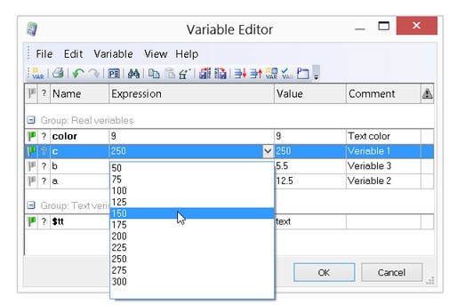
The list of variable's values
For any T-FLEX CAD variable it is possible to define a list of values. To be more precise – a list of expressions since the list for the variable can include any values, not necessarily the constants. The list of various expressions can be defined even for a variable-function. After that, the value of any variable, more precisely, of any expression, determining this value, can be selected from the created list.
The list is created as a set of lines, containing required constants or expressions. Moreover, the list can be created on the basis of already existing file, internal database, the list of materials in the 3D version or the calendar two last items are available only for text variables.
The list defined for the variable will appear in all places in which the value of the given variables is specified (in the variables editor, in the command “М: Edit model parameters”, upon assigning the variables of a fragment). The field for the entry of the values of such variable will include the graphic button ![]() which enables to call the list of values. To access the list of values, it is enough to point at this button with the cursor of the mouse and press
which enables to call the list of values. To access the list of values, it is enough to point at this button with the cursor of the mouse and press ![]() . As a result, the list will pop up on the screen, and the new value (expression) can be selected from the list.
. As a result, the list will pop up on the screen, and the new value (expression) can be selected from the list.
Comment of variable
If necessary, for any variable the comment can be specified. It represents itself an arbitrary text string. The comment enables to “attach” certain clarifications to the variable. For example, the comment may clarify the variable's designation (the width of the part, the radius of the circle, etc.) or the range in which the value of the variable is changed.
The comment of the variable, if it is specified, will appear in the dialog for inserting a variable (this dialog can be called, for example, from the context menu of all fields of the system dialogs), and also from the list of the values of the fragment upon its insertion into a drawing or 3D model.
Group of variables
If necessary, for any variable the group can be identified. When the variables are broken down into the groups, it becomes easier to control the large list of variables of the complicated drawing.
The Group, as well as the comment, is an additional characteristic of the variable specified for simplifying the work with a large number of variables. The fact that the variable belongs to a certain group does not affect in any way the use of this variable.
External Variables
Any variable, the value of which is specified by a constant (numeric or character), can be given an attribute “external”. External variables are used for organizing parametric connection between the assembly document and the fragments. The values of the external variables, defined in the fragment, can be modified from the assembly document.
The variables, marked as external, can be exported to the external text file with the possibility of reading from this file afterwards. This enables to use external variables for organizing connection between the T-FLEX CAD and other systems and application programs.
Hidden Variables
For regulating the work with a large number of variables, the mechanism of hidden variables can also be used.
Any variable, created in the T-FLEX CAD document, can be marked as hidden. By default, such variables are not displayed in the window of the variables editor or in the windows of other T-FLEX CAD dialogs dealing with the variables. Thus, it is possible to hide various auxiliary variables.
All standard templates of the T-FLEX CAD documents already contain a list of hidden variables providing automatic cross-reference between the fields of the drawing format (the title block) and the BOM data. In other words, the textual strings of these variables are substituted in both the appropriate title block fields and the respective entries of the BOM data.
Used and used variables
In order that the value of the variable could affect the structure of the drawing (or 3D model) of the given document, it is not sufficient just to create this variable in the T-FLEX CAD document. The given variable has to specify a characteristic of the elements of the drawing or 3D model: location of a line or a node, the radius of a circle, the level of visibility of the image line or 3D bodies, etc.
The variables the values of which take part in specifying characteristics of other elements will be further called used. Also, the variable is considered to be used, when its value is used for evaluating the value of another variable.
Consequently, the variables the values of which are not used anywhere on the drawing or in the 3D model and also upon calculation of the values of other variables are considered to be unused. Such variables, being equal variables of the T-FLEX CAD document, do not have any influence on its content.
Work in Variables Editor
Window of Variables Editor
The work with the editor can be carried out in two ways. The first way – the work in the main window of the variables editor, called with the help of the command “V: Edit variables”. The dialog box of the given window enables to use the entire functionality of the variables editor and possesses a convenient interface. However, all changes made in the given window will be applied to the model only after closing the window of the dialog box.
The second way – is to use a special service window of the system – the window “Variables”. This window enables to work with the variables in the transparent mode.
In this chapter the description of work with the variables editor will be further presented by taking the standard window of the variables editor as an example. However, the same operations can be performed in the window “Variables”. The work with the window “Variables” will be discussed in the section “Working with variables editor in transparent mode” in a more detailed manner.
To call the main window of the variables editor, the command “V: Edit variables” is used:
Icon |
Ribbon |
|---|---|
|
Title Block → Additional → Variables |
Keyboard |
Textual Menu |
<V> |
Parameters > Variables |
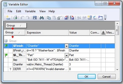
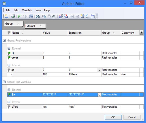
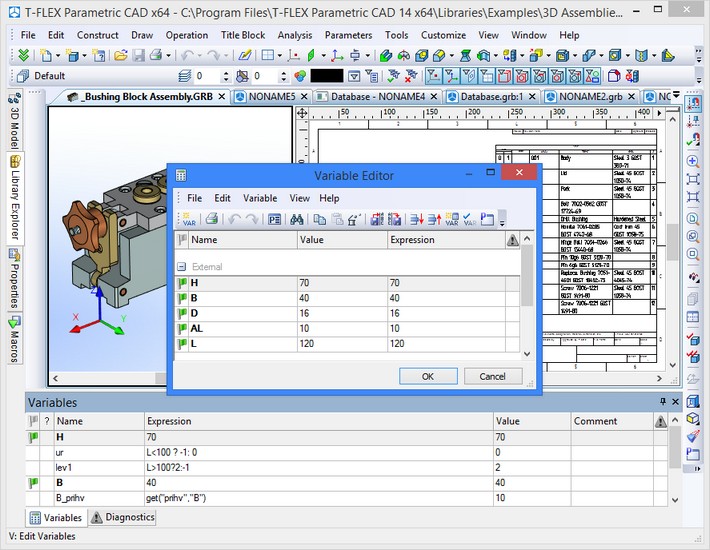
The window of the variables editor contains the list of all variables of the current T-FLEX CAD document no matter in what way they were created (recall that the new variables can be created not only in the variables editor). Upon calling this command, the window of the variables editor will be empty if no single variable has been created in the document.
In the editor window, the variables list is displayed as a table, the form of which can be freely edited by a user. It is possible to modify the number and content of the displayed columns, the parameters for grouping and sorting the rows of the table, parameters of the grid of the table.
The variables editor has its own textual menu and the toolbar containing the main commands for working with the variables.
Creating Variable
In the variables editor the new variable can be created by using the command “New Variable”:
Keyboard |
Textual menu |
Icon |
|---|---|---|
<Ctrl><N> |
«Variable|New» |
|
After calling this command, the window for specifying properties of the variable being created appears. For creating a variable it is necessary to indicate the name, type of the variable (real or text), and also specify an expression, which will determine the value of the given variable.
The field “Name” and the toggle “Real/Text” work in a synchronized manner. For example, if the specified name of the variable starts with the symbol “$”, then the type toggle is automatically switched to the value “Text”. And vice versa – upon changing the type of the variable, the symbol “$” is automatically added/removed to/from the name of the variable.

Parameters “Comment” and “Group” do not have to be specified.
By default, the parameter “Group” takes the same value as the variable selected in the table of variables upon calling the command “New Variable”.
The flag “External” is turned on if the variable being created has to be external.
In the table of variables the names of the external variables are marked with bold font.
The flag “Hidden” is turned on if the variable being created has to be hidden.
The flag “Function” is set on only in case it is necessary to create a variable-function. In this case the expression has to be made up with the use of the notation for the arguments of function (#1, #2, #3…).
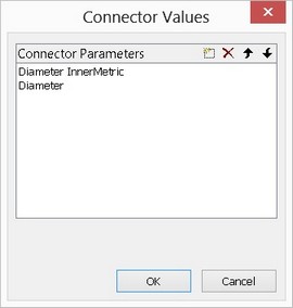
If the current document is going to be used as a fragment, then for its external variables, the assembly variable name and/or the list “connector values”. can be also indicated in the dialog “Variable's Properties”. What that means will be discussed in detail in the chapter “Creating assembly drawing”. The name of the assembly variable is defined in the field of a single-named parameter, and the list of connector values – in the dialog box “Connector values” emerging upon pressing the button [Connector values…].
The list “Connector Values…” is filled up for external variable of a document, used as a fragment with fixing by connector. Upon inserting such fragment into an assembly, the system has to automatically change the value of the fragment's external variable in accordance with the given (“values”) of the indicated connector. The system selects the name of the required value of the connector in the list “Connector values” for the external variable. Upon fixing the fragment to the connector, the system will be first looking for the first name from the list, among the named connector values, and if it is not found – the second name and so on.
The list of connector values may contain arbitrary number of elements. For creating a new element of this list, the button |
|
The group of parameters “Value List” enables to create and edit the list of values for a variable. If a given variable does not have the list, then the value “No” will be specified in the drop-down menu of the given group. For creating the list it is necessary to select from the menu the required creation method: “Text”, “Database”, “File”, “Data”, “Materials”. More detailed description of various methods of creating the list of variable’s values is presented below in the section “Creating List of Variable’s Values”.
After pressing [OK] the created variable appears in the list of variables.
It is recommended to use uncomplicated names for the variables in order not to write lengthy expressions. It is a good thing to write a comment for each variable.
The command “New Variable” can be also called from the context menu at any place of the list of variables.

Besides the use of the aforementioned method, it is possible to create a new variable by other means. It is enough to put the name of yet non-existing variable into the expression of some variable. After recalculation of the given expression the system will find that such variable (for example, the variable “С”) has not been defined, and a message will pop up on the screen: “Create variable “C”?”. If the question is answered positively, the new variable will automatically appear in the list of variables, and the focus of input will be moved to its field “Expression” – for specifying the expression for this variable. In case of a negative answer, the new variable is not created and the error message is generated.
Creating List of Variable's Values
The list of variable’s values is created with the help of the parameter “Value List” in the variable’s properties window. The method by which the variable’s list is created is chosen from the pull down menu of this parameter: “Text”, “Database”, “File”, “Data”, “Materials”.
After selecting the list creation method on the basis of text, the window of the text editor will appear, in which the necessary list of values can be formed. Each value has to be located in a separate line. Upon creating the list, all options of the text editor become available.
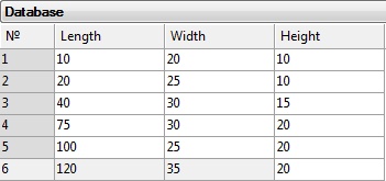
When the list is created on the basis of database, already existing internal database is used. For example, let's suppose there is database shown on the picture. After calling the command for creating the list on the basis of database, the dialog window will appear. The parameters for forming the list have to be indicated in this window. One has to choose: -the name of the database from the list of databases for the current document; |
|
|||
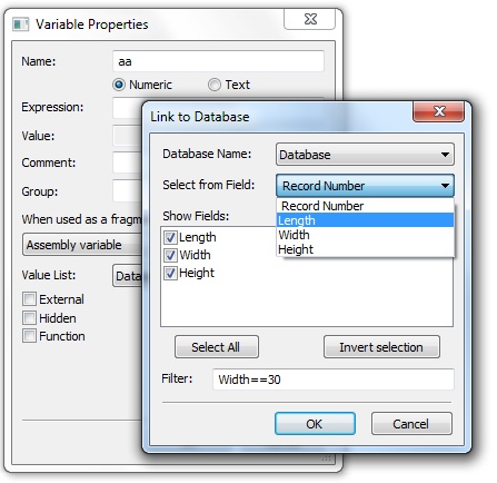
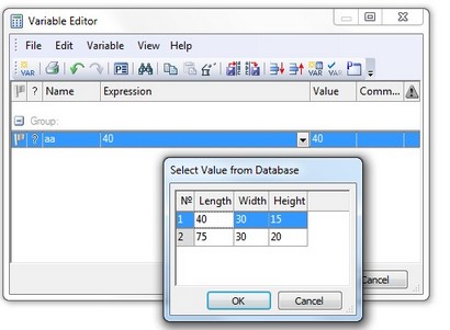
-the column in the database from which the values will be selected. The first line of the list – “Record number” can be also chosen. In this case, the selected record number will be a value being returned; -columns which will appear upon creating the list. The field “Filter” enables to specify conditions for the values selected from the database (upon creating the list of values). These conditions are specified with the help of logic expressions, which are made up by the same rules as those for the expressions for the variables (see chapter "Functions for Working with Variables"). For example, the use of the expression, shown on the picture above, will lead to the result shown on the picture below (for comparison, the list obtained in the same example without specifying the condition in the field “Filter” is shown as well). |
|
|||
|
|
|||
List on the basis of database obtained with the use of filter |
List on the basis of database obtained without using the filter |
|||
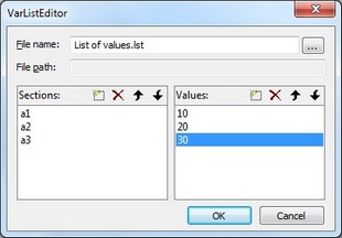
When the list is created on the basis of file, the dialog window for selecting already existing or creating the new file appears. The data in the file must be stored in the form of sections with the lists of values. Upon creating the list, the required section is indicated. Also, it is possible to create the new section or remove already existing section from the file with the help of buttons The list of values for the selected section is shown in the field on the right. The buttons |
|
|||
The created file can be used while working with other TFLEX CAD documents.
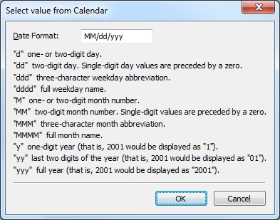
When the list is created on the basis of date, the dialog window pops up, in which the date representation format can be specified, for example, “DD.MM.YY”. The variable, for which this list is specified, has to be a text variable. After that, upon making a selection from the list, the window in the form of a calender will emerge, in which any required date can be chosen.
|
|
Also, it is possible to form the list on the basis of materials list (only in 3D version of the system). Such list can be formed only for the text variable. Upon creating the list, the window of the text editor appears, in which all materials, used in the 3D model of the current document, are included by default. If necessary, the list can be edited manually.
In order to edit the created list, it is necessary to use the button [Edit…] of the group “Value List”. For each type of the list, the corresponding edit method will be called.
For removing any list of values, it is enough to put again the value “No” in the drop-down list of the group “List”. If the list is created on the basis of database, then only connection with the database will be broken, the database itself will be preserved.
Window “Assistant”
To specify the values of the variables, the user can use a special auxiliary window “Assistant”:
Keyboard |
Textual menu |
Icon |
|---|---|---|
<Ctrl><H> |
«View|Assistant» |
|
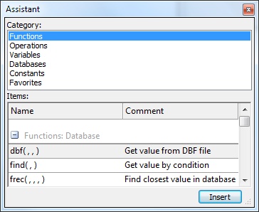
Assistant is used for quick insertion of functions’ names, records from the databases, variables already existing in the document, frequently used constant, etc. into the expressions of variables.
For convenience the contents of the Assistant is divided into several categories. The list of available categories is displayed in the upper part of the Assistant window in the field “Category:”. The contents of the category selected in the field “Category” is displayed in the lower part of the window. For example, on the picture to the right the list of standard mathematical function of the T-FLEX CAD is shown in the Assistant window. For each function there is a short description. To insert a function (a link to a field in the database, an operation, a variable, etc.), the user needs to select a desired category in the Assistant window, then select a required line in the category contents list and finally press When working with the variables’ editor, the window “Assistant” can be placed on the screen permanently. |
|
Properties of Variable
For changing the name, expression or other characteristics of variables, the variable's properties dialog box, called with the command “Properties”, is used:
Keyboard |
Textual menu |
Icon |
|---|---|---|
|
«Variable|Properties …» |
|
The command “Properties” can be also called from the context menu, activated with the ![]() upon choosing the variable in the list of variables. Or it can be called just by pointing with the cursor at the variable's name in the list of variables and pressing
upon choosing the variable in the list of variables. Or it can be called just by pointing with the cursor at the variable's name in the list of variables and pressing ![]()
![]() .
.
After calling this command, the window of the dialog “Variable's Properties” will appear. Inside this window it is possible to modify the name of the variable, its expression, comment and group, by using corresponding fields of the dialog. It is possible to mark this variable as external or hidden (flags “External” and “Hidden”).
The command “Properties” can be also accessible when several variables are selected simultaneously. In this case, when this command is called, the window emerges in which for selected variables the only parameter: group can be specified. Selection of several variables is carried out with the help of <Ctrl>+![]() , <Shift>+
, <Shift>+![]() .
.
Removing Variable
It is possible to delete the variable with the help of the following command of the variables editor:
Keyboard |
Textual menu |
Icon |
|---|---|---|
|
«Edit|Delete» |
|
The command “Delete” can be also called from the context menu upon choosing the variable in the list of variables.
After calling this command, the variable, for which this command was called, will be removed. Note that, only unused variables can be removed (in the column “Not used” a symbol “?” will be standing next to such variable). The command “Delete” is not available for used variables.
In case if the variable is currently used, the user has an option of either deleing the chain of dependent elements or replacing the selected variable with a constant value.
Diagnostics of Errors
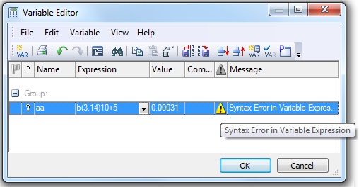
Upon creating the new variables and also the further work with the variables, various errors can arise. Usually these are the syntax errors in the expression of the variable. In this case, for the problem variable the sign ![]() will be shown in the column “State”. Upon bringing the cursor to this sign, a tooltip about the type of the error will appear. At the same time, the color of the field “Value” will be changed to red manifesting the existence of the error. In addition, for the given variable a detailed description of the arisen error will appear in the column “Message” (by default this column is turned off).
will be shown in the column “State”. Upon bringing the cursor to this sign, a tooltip about the type of the error will appear. At the same time, the color of the field “Value” will be changed to red manifesting the existence of the error. In addition, for the given variable a detailed description of the arisen error will appear in the column “Message” (by default this column is turned off).
In spite of the existence of errors, it is possible to finish the work in the variables editor, and get back to their correction later. The existence of errors in the variables editor does not affect the recalculation of the 2D/3D model elements of which depend on the incorrect variables.
If necessary, you can track the use of any variable in the model with the help of the “The use of a variable” command found in the context menu of the variable.
Canceling Operations in Variables Editor
Any actions in the variables editor can be canceled/repeated with the help of step-by-step commands:
Keyboard |
Textual menu |
Icon |
|---|---|---|
<Ctrl><Z> |
«Edit|Undo |
|
<Ctrl><Y> |
«Edit|Redo» |
|
The number of cancellation steps is limited only by general setting of the system (parameter “Undo/Redo Buffers” in the dialog of the command “Customize|Options…”, the tab “Preferences”).
Show/Hide Hidden Variables
Command «Show/Hide hidden variables» ![]() shows or hides hidden document variables in one click. State is maintained in user settings.
shows or hides hidden document variables in one click. State is maintained in user settings.

Customizing Window of Variables Editor
The appearance of the table of variables in the window of the variables editor can be customized with the help of command:
Keyboard |
Textual menu |
Icon |
|---|---|---|
|
«View|Options…» |
|
Moreover, this command can be also called from the context menu at any place of the variables editor.
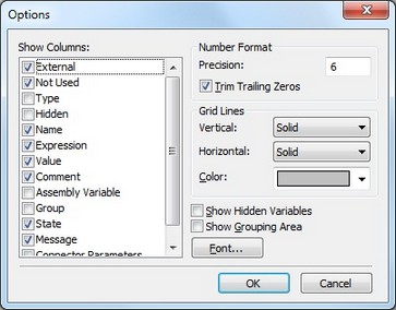
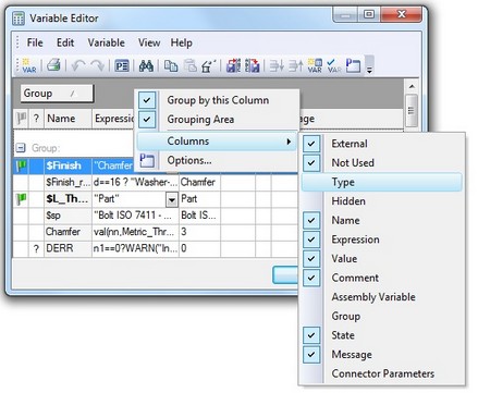
After calling this command the window “Options” opens up. At the left pane of the window, the list of all possible columns from the table of variables will be displayed.
The majority of the columns correspond to some characteristic of the variable (name, type, usability, expression, current value, and so on). The columns “State” and “Message” are used for output of system messages about errors upon evaluation of the value of variable. The columns displayed at the current moment are marked with a tick before the name. To add the column into the table, it is enough to select it in the list and with the help of In the right pane of the window “Options” there are other various parameters of the table of variables: |
|
The group “Number Format” sets the format for the real numbers in the column “Value”: “Precision” and “Trim Trailing Zeros”.
The group “Grid Lines” defines the appearance of the grid of the table of variables:
Vertical. The appearance of vertical lines of the grid of the table: “No”, “Small dots”, “Large dots”, “Dashed”, “Solid”.
Horizontal. The appearance of horizontal lines of the grid of the table: “No”, “Small dots”, “Large dots”, “Dashed”, “Solid”.
Color. The color of grid lines of the table of variables.
Show Hidden Variables. This flag controls the view of hidden variables in the table of the variables editor.
Show Grouping Area. This parameter controls the view of the grouping area over the table of variables (see below).
The button [Font…] enables to set the font used upon displaying the table of variables in the window of the variables editor.
The visibility of single columns of the table can be customized without calling the command “Options”. To do that, it is enough to call the context menu from any place on the header of the table of variables. Submenu “Columns” enables to quickly turn off/turn on the display of the columns.
The order in which the columns are displayed in the table of variables can be easily changed just by pulling over the columns into the required places. To do that, it is enough just to bring the cursor to the column, hit ![]() and without releasing the mouse button, drag the header of the column to the required place. Red arrows on the screen suggest where the column will be inserted.
and without releasing the mouse button, drag the header of the column to the required place. Red arrows on the screen suggest where the column will be inserted.
Grouping Area. Grouping of Variables
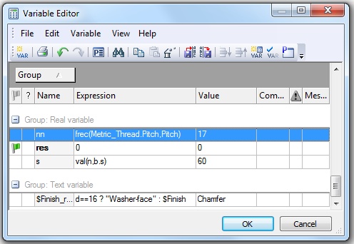
By default, in the variables editor all variables are grouped by the characteristic “group” (if this characteristic is specified for variables of the current document). However, it is possible to use other parameters of variables for grouping, including several parameters at the same time.
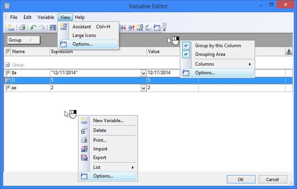
For customizing the grouping parameters it is convenient to use the grouping area. It is turned on via the dialog of the command “View|Options…” or via the context menu in the header area of the table of variables. The grouping area is situated over the table of variables. By default, the label “Group” is displayed in the grouping area. This means that the variables are grouped by the characteristic “group”.
In order to turn off the grouping, it is enough to point with the cursor at the label in the grouping area, press ![]() and without releasing the mouse button, drag the label to any other place outside the grouping area. If the label is moved to the headers' bar of the table of variables, the column with the same name will be added to the table. If the label is moved while holding the key <Ctrl>, the label will be copied – it will remain in the grouping area, and at the same time the corresponding column will appear in the table.
and without releasing the mouse button, drag the label to any other place outside the grouping area. If the label is moved to the headers' bar of the table of variables, the column with the same name will be added to the table. If the label is moved while holding the key <Ctrl>, the label will be copied – it will remain in the grouping area, and at the same time the corresponding column will appear in the table.
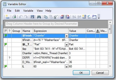
When the mode of grouping is turned off, the message “Drag Column Header here to group by Desired Parameter” is displayed in the grouping area.
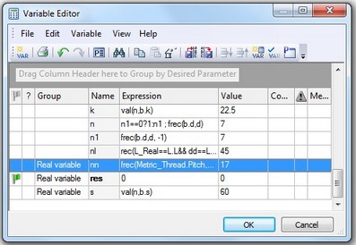
To activate the mode of grouping by some characteristic, it is enough to point at the header of the corresponding column of the table of variables, press ![]() and without releasing the mouse button, drag the header of the column to the grouping area. After that, the label of the chosen characteristic will appear in the grouping area, and the variables in the table will grouped by this characteristic. If the headers of two columns of the table are moved to the grouping area, the grouping will be carried out by two characteristics simultaneously. Location of the labels in the grouping area shows the order of grouping.
and without releasing the mouse button, drag the header of the column to the grouping area. After that, the label of the chosen characteristic will appear in the grouping area, and the variables in the table will grouped by this characteristic. If the headers of two columns of the table are moved to the grouping area, the grouping will be carried out by two characteristics simultaneously. Location of the labels in the grouping area shows the order of grouping.
Note that upon moving the header of the column into the grouping area, the column is removed from the table. In order to keep this column in the table, it is necessary to hold the key <Ctrl> while moving the header.
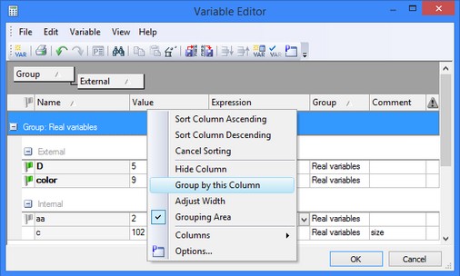
It is also possible to control grouping with the help of the context menu. It is sufficient to point the cursor at the column header of the table of variables and call the context menu with the help of ![]() . The flag “Group by this Column” will be accessible in the context menu. In order to activate grouping by this column, this flag should be set on. To cancel grouping by selected column, it is enough to take this flag off.
. The flag “Group by this Column” will be accessible in the context menu. In order to activate grouping by this column, this flag should be set on. To cancel grouping by selected column, it is enough to take this flag off.
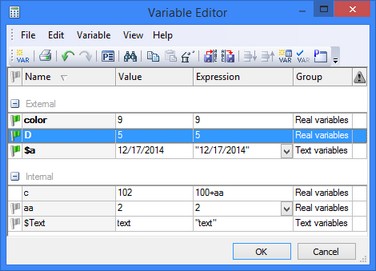
Sorting Variables
In addition to grouping, for the list of variables it is possible to specify sorting by any column. By default, the sorting is turned off. To turn it on, it is enough to bring the cursor to the header of that column of the table of variables by which the variables are to be sorted. The tooltip “Sorting by: …” with the name of the selected column will appear on the screen. If one hits ![]() pointing at the header of the column, then the rows of the table of variables will be sorted by the selected characteristic. In the header of the column, by which the sorting is carried out, an additional symbol in the form of a triangle will appear, showing the direction of the sorting:
pointing at the header of the column, then the rows of the table of variables will be sorted by the selected characteristic. In the header of the column, by which the sorting is carried out, an additional symbol in the form of a triangle will appear, showing the direction of the sorting: ![]() – for sorting in ascending order,
– for sorting in ascending order, ![]() – for sorting in descending order.
– for sorting in descending order.
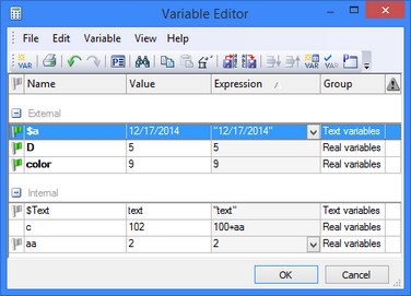
By default the mode of sorting in an ascending order is turned on initially. Pressing ![]() on the header of a column repeatedly turns on the sorting in a descending order. For sorting by another characteristic, it is enough to press
on the header of a column repeatedly turns on the sorting in a descending order. For sorting by another characteristic, it is enough to press ![]() on the header of the corresponding column.
on the header of the corresponding column.
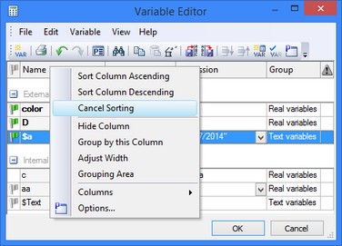
Sorting can be canceled with the help of the command “Cancel Sorting” in the context menu called from the headers' bar of the table of variables (i.e. in the area of the header of any column of the table). This command is available only when the mode of sorting is turned on. Also, in the context menu the commands “Sort Column Ascending” and “Sort Column Descending” are available. They activate sorting by the column for which, in the column header, the context menu was called.
Sort parameters are saved in the file of the document and restored upon reentry into the variable editor. To change the order of rows in a table the buttons can also be used:
●![]() - Move downwards.The current row will be moved to the row below.
- Move downwards.The current row will be moved to the row below.
●![]() - Move upwards.The current row will be moved to the row above.
- Move upwards.The current row will be moved to the row above.
These commands are also accessible via the text menu of the variables’ editor:
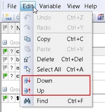
When sorting capability is turned off the user can also utilize <Ctrl>+<ArrowUp>, <Ctrl>+<ArrowDown> to change the order of the lines in the variable editor. The changes in the sequence of the lines are saved in the document’s file separately for the main window of the variable editor and for the auxiliary window “Variables” (see section “Working with variable editor in transparent mode”).
Finding Variables
Upon working with a large list of variables, it is sometimes convenient to use the command of searching for variable by name:
Keyboard |
Textual menu |
Icon |
|
Edit > Find |
|
After calling this command the dialog window pops up, in which the search parameters are required to be specified. After specifying the parameters, the button [Find Next] has to be pressed. If the search process was completed successfully, the cursor is moved to the column “Expression” for the found variable. If the variable was not found, the cursor stays at the same place, and in the message line of the editor the message appears: “Cannot find specified string”. |
|
Upon specifying parameters it is important to pay attention to the state of the flag “Match Case”. By default, this flag is activated. In this case the system looks for the variable, the name of which coincides exactly with the specified string in the field “Find what”. When this flag is off, the system searches for the variable for which the text, specified in the field “Find what”, enters the variable's name as a substring.
In all columns. The option allows finding of the specified string in all columns.
Copying Variables
The T-FLEX CAD makes it possible to copy variables from one document to another with the help of the clipboard.
For copying one variable to the clipboard it is necessary to select it in the table of variables with the help of ![]() , and after that call the command “Copy”:
, and after that call the command “Copy”:
Keyboard |
Textual menu |
Icon |
|---|---|---|
<Ctrl><C> |
«Edit|Copy» |
|
For inserting the already copied variable, the command “Paste” is used:
Keyboard |
Textual menu |
Icon |
|---|---|---|
<Ctrl><V> |
«Edit|Paste» |
|
If the document, in which the insertion is performed, already contains the variable with the same name as that of the variable being inserted, the message “Some Variables have equal Names” pop up.
If the document, in which the insertion is performed, already contains the variable with the same name as that of the variable being inserted, the message “Some Variables have equal Names” pop up.
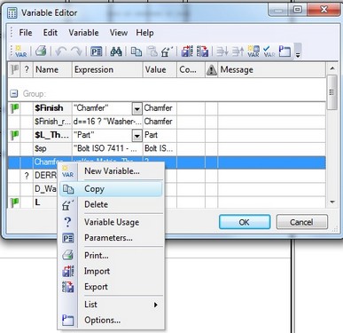
The commands of copying/insertion can be also called from the context menu for the variable:
For copying several variables simultaneously, a multiple selection with the help of <Shift>+![]() and <Ctrl>+
and <Ctrl>+![]() is used. For selecting all variables of the given document at once, the following command is used:
is used. For selecting all variables of the given document at once, the following command is used:
Keyboard |
Textual menu |
Icon |
|---|---|---|
<Ctrl><A> |
«Edit|Select All» |
|
Writing Variables to External File
The values of variables can be written into the file of parameters by using the command “Export Parameters”:
Keyboard |
Textual menu |
Icon |
|||
|
«File|Export» |
|
|||
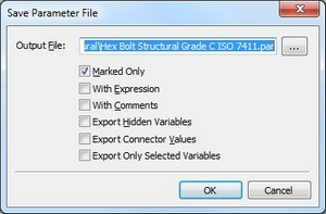
Upon calling this command the dialog window appears. One needs to specify the name of the file, into which the information will be written. By default, the filename coincides with the name of the current drawing, file extension is – “par”. It is possible to specify an arbitrary filename. Each variable is written in a separate line. The format of the record is the following: <name of variable> = <value> [/*<comment >*/] The name and the value of the variable are always written down. |
|
||||
The comment is written on condition that one of the following parameters has been set on: “With Expressions” or “With Comments”.
If in the export dialog box the flag “Marked Only” is activated, then only external variables of the given document will be written into the resulting file. When the flag is taken off, all visible variables are exported.
Hidden variables are not exported by default. In order to write them into the external file as well, it is necessary to set on the flag “Export Hidden Variables”.
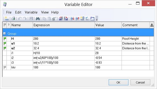
For example, suppose there is the following list of variables in the editor:
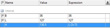
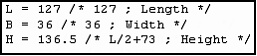
Upon writing the file, the following parameters have been activated: output all variables except hidden ones, with expressions and comments. This has to result in the file with the following content:
If you select "Export connector values", the output file will have values added from the corresponding column.
If you select "Export only selected variables", the output file will have only selected rows.
The values of external variables can be read from the file of parameters by using the command “Import Parameters”:
Keyboard |
Textual menu |
Icon |
|||
|---|---|---|---|---|---|
<Ctrl><R> |
«File|Import» |
|
|||
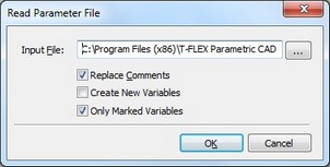
After calling this command the dialog window pops up. If the variable present in the file of parameters is absent in the current drawing, it will not be read. Also, the variables that are not defining in the drawing as external will not be read. How can files of parameters be used? |
|
||||
Files of parameters can be used when you need to save several versions of the same drawing. In this case you save several files of parameters with the values of external variables and, if necessary, read the values from a specific file. As a result, a finished drawing with the required parameters is obtained.
It is convenient to use the files of parameters for connection of the T-FLEX CAD with other computational software. In the system you can create a parametric drawing with certain set of parameters. Your computational procedure receives the values of these parameters through the file. You calculate the remaining parameters of the drawing in your software and create either a new file of parameters or update the old one. From the TFLEX CAD you read the file and obtain a modified drawing on the basis of the parameters calculated by you. Thus, the file of parameters serves as an intermediate link for connection between the T-FLEX CAD and your software.
Printing List of Variables
For printing the content of the variables editor the command “Print” can be used:
Keyboard |
Textual menu |
Icon |
|---|---|---|
<Ctrl><P> |
«File|Print…» |
|
After calling this command the standard printing options dialog appears. As a result, all content of the variables editor will be sent to printer in the same form as it was displayed on the screen.
Before calling this command, separate lines from the table of variables can be picked out in the window of variables editor with the help of ![]() , <Ctrl>+
, <Ctrl>+![]() , <Shift>+
, <Shift>+![]() . Then by setting on the flag “Print range|Selection” in the printing options dialog, it is possible to print out only selected lines and not the entire content of the editor.
. Then by setting on the flag “Print range|Selection” in the printing options dialog, it is possible to print out only selected lines and not the entire content of the editor.
Working with Variables Editor in Transparent Mode
To work with the variables editor in the transparent mode (while working simultaneously in the drawing or 3D model window), the service window of the system “Variables” can be used. Similar to other service windows of the system, the window “Variables” can operate in floating and popup mode. Also it can be placed along one of the sides of the main window of the system.
By functionality the window “Variables” duplicates the main window of the variables editor, called with the command “V: Edit variables”. But the textual menu and the toolbar are absent in the window “Variables”. All operations with the variables in the window “Variables” can be carried out only with the help of the context menu and hot buttons. Such simplification of the interface is completely compensated for by the transparent operation with the variables. With the help of the window “Variables”, it is possible to edit variables while being in any command. Upon changing the expression of the variable in the window “Variables”, automatic recalculation of the drawing (or 3D model) is carried out. All changes are immediately displayed in the window of the system.
Editing External Variables
External variables are usually widely used in the T-FLEX CAD documents for organizing parametric connection between assembly document and fragments, and also for organizing connection of the TFLEX CAD with other systems and applications.
For editing variables, marked as external, besides the variables editor, the command “M: Model Parameters” can be used:
Icon |
Ribbon |
|---|---|
|
Parameters → GUI Control → Model |
Keyboard |
Textual Menu |
<M> |
Parameters > Model |
In contrast to the variables editor, only those variables of the current document which are marked as external are displayed in this command. This command does not allow a user to create new variables. Thus, if there are no external variables in the drawing, the message “No external variables” is produced and the command is not called.
The kind of the dialog box used in this command depends on the attribute setting “External variable editor” in the command “ST: Set Document Parameters” (the tab “External Variables”). This attribute can assume one of the following settings:
●Internal Editor. Upon calling the command “М: Model Parameters”, the Variable Editor dialog box comes up for editing external variables, that looks similar to the normal variable editor window;
●External Program. In this case, the appearance of the dialog box is defined by the external custom application;
●Control. The user might have created a custom dialog box using interface elements (see the chapter “Control Elements. Creating User Defined Dialog Boxes”). In such a case, calling the command “М: Model Parameters” brings up this dialog box.
The command “M: Model Parameters” can be used for modeling the process of editing external variables of the fragment in an assembly. One more possible way of using this command – when too many expressions are specified in the current drawing. In this case it is possible to mark the variables on which the remaining variables depend as external ones, and, if necessary, modify their values in the external variables editor.
Upon changing the values of the external variables with the help of the command “М: Model parameters”, only constants can be used as admissible values of variables.
After completing the command, all variables are recalculated per the changes to the external variables, and the drawing is regenerated with the new parameters.
Use of variables in T-FLEX CAD
The variables and expressions created within the variable editor do not affect the drawing in any way per se. The variable editor in itself is merely a powerful calculator. However, the variables can be used in T-FLEX CAD system in many various ways.
Variables and construction lines
The main application for numerical variables is their use as construction line parameters.
A variable can be assigned as a parameter to a construction line in the following two ways:
When creating construction lines in the commands "L: Construct Line", "C: Construct Circle" and "EL: Construct Ellipse". This can be done in the dialog of the properties window for the given commands or in the dialog of the construction line parameters, called with the help of the option <P>.
When editing construction lines in the command "EC: Edit Construction". To do that, it is necessary to choose a line in the edit command. After that, it is possible to specify the variable as a line parameter in the dialog of the properties window or in the dialog of the line parameters, called with the help of the option <P>.
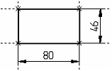
Your actions for defining a construction line parameter via a variable are the same in both cases. Therefore, consider only the example of editing construction lines. In this example, the left and bottom lines are constructed as vertical and horizontal respectively. The right and top lines are constructed as parallel, accordingly.
Save this drawing with a certain name, say, TEST, as it will be further used for describing variable uses.
Call the command "EC: Edit Construction". Select the right vertical line. In the dialog of the properties window place the cursor into the field of the parameter “Distance”.
The distance from the reference line is a parameter of a parallel line, and, by default, this distance was specified as constant. Replace the value by the expression "-A".


Hit ![]() at any place of the drawing. Two outcomes are then possible: - if the variable A exists, then the construction line will adjust to the variable value. - if the variable does not exist, then the dialog box will appear on the screen for defining the value of the new variable. You can then also mark the variable as external.
at any place of the drawing. Two outcomes are then possible: - if the variable A exists, then the construction line will adjust to the variable value. - if the variable does not exist, then the dialog box will appear on the screen for defining the value of the new variable. You can then also mark the variable as external.
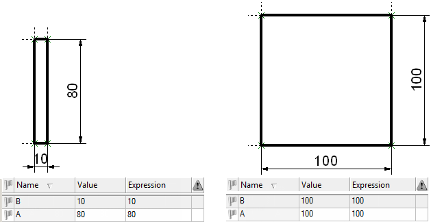
After pressing [OK] the construction line will be adjusted in accordance with the value of variable. By doing the same with the top horizontal line and defining its parameter by a variable B, you establish relation between the variables and the construction lines. From now on, the construction line positions will be driven by modifications in the variables A and B.
Note that construction line parameters can be defined by variables only when the option ![]() or <P> is available. (Refer to the commands "L: Construct Line", "C: Construct Circle", "EL: Construct Ellipse").
or <P> is available. (Refer to the commands "L: Construct Line", "C: Construct Circle", "EL: Construct Ellipse").
To clearly witness the relation between the construction lines and the variables, let's complete the drawing.
Draw the graphic lines using the command "G: Create Graphic Line" and apply the dimensions between the vertical and the horizontal lines using the command "D: Create Dimension". After that, in the window “Variables” or in the main window of the variables editor (called with the command “V: Edit Variables”), change the value of variables A and B.
Note that modifications in variables and expressions driving the construction lines, also affect the dimension display and dimension values. The dimensions themselves can be also used for modifying position of the construction lines, with which these dimensions are connected, and as a consequence, values of the variables determining parameters of these lines. To do that, it is necessary to point the cursor at the dimension value and hit ![]() . Chosen dimension value is selected for editing. Upon modifying the dimension value, the system automatically changes position and parameters of construction lines, on which the given dimension is based. If position of the given line was determined by a variable, the value of this variable will be also changed.
. Chosen dimension value is selected for editing. Upon modifying the dimension value, the system automatically changes position and parameters of construction lines, on which the given dimension is based. If position of the given line was determined by a variable, the value of this variable will be also changed.
When using variables as construction line parameters, try not to use complicated expressions. The recommended approach is defining construction line parameters via a standalone variable or a simple expression. All complicated mathematical relations can then be defined within the variable editor. This helps keeping definitions in one place, without need of visiting all possible commands and searching through all elements for handling.
Variables and visibility levels
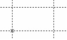
It is often convenient to define visibility level values by variables. This helps covering a wider variety of configurations by a single parametric model. Consider, for example, the parametric drawing on the diagram. The two views are interdependent. The slanted line was constructed as passing through a node, at a specified angle to the horizontal. A variable AL is introduced as the parameter of the line. The configuration on the diagram corresponds to the value of AL = 130. Let's modify the variable value to AL = 60.
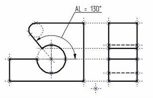
The upper dashed graphic line on the side view stays after modifications, which is wrong. This graphic line was originally created on top of a construction line parallel to the horizontal line and tangent to the circle. This flaw can be fixed by using the variable LEVEL as the value of the visibility level of the dashed graphic line. The value of this variable can be defined by the following expression: LEVEL = AL > 90 ? 0 : -1
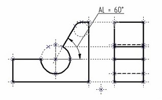
The visibility interval for graphic lines is set from 0 to 127 (inclusive). In our case, if the variable AL is greater than 90, then LEVEL equals 0, which is within the visibility interval. Therefore, the graphic line will be drawn. If AL is less than 90, then LEVEL = -1, which is outside the visibility interval, and the graphic line will not be drawn. This drawing sample can be found in the directory "Examples/Parametrization\Variables\Variables and visibility on levels.GRB".
This approach allows creation of models representing a family of product modifications. An example could be a drawing of a bolt with various head styles.
Variable dependency
Variable interdependencies with other elements can be examined with the help of the command "SR: Show Variable links". The command is called as follows,
Icon |
Ribbon |
|---|---|
|
Parameters → GUI Control → Links… |
Keyboard |
Textual Menu |
<SR> |
Parameters > Links… |
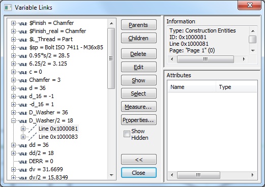
As a result of calling the command, the dialog box appears, listing all the variables of the drawing and their values in a tree layout. By default, only the visible variables are in the list. To view all variables of the given document (including hidden), set the flag "Show Hidden Variables".
The "+" glyph in a box before a variable indicates a collapsed branch. Such a branch contains a list of one or more drawing elements that rely on the variable. To expand the list, point and click the left mouse button over the box. The list contains element types and Ids.
The listed elements, in turn, may be constructed based on other elements. In such a case, their branches will also be preceded by the box with the plus inside. The base (independent) elements in construction hierarchy are on plain branches, not prefixed with the box. The pane on the right-hand side of the dialog box displays information about the selected element. Besides that, the selected element is highlighted in the drawing or in the 3D window.
Besides viewing relations of variables with drawing elements, you can additionally perform certain manipulations with 2D or 3D elements selected in the list, using the following buttons:
[Parents] Upon clicking this button, the dialog window displays the tree of parent elements for the element selected in the list, instead of the list of all variables. This button is unavailable for the elements without parents.
[Children] Works similar to the previous button, but instead of the parent element tree displays the children's tree for the selected element.
[Delete] Closes the command window and calls the command to delete the selected element.
[Edit] Closes the command window and calls the command to edit the selected element.
[Show] Closes the command window. The current drawing (model) working window is adjusted so as to fully display the selected element on the screen.
[Select] Closes the command window. The selected elements stay selected for further manipulations.
[Measure…]. Calls the command "PM: Measure Element or relation between two Elements" for the selected element.
[Properties…] Calls the parameters dialog for the selected element. After finishing working with the dialog, the "SR: Show Variable links" command window is resumed.
[Close]. Exits the command.
[<<] [>>] Open and close an additional console in the «Information» dialog window, containing the following fields:
Information. This field displays a brief information about the selected object.
Attributes. This field displays information about the attributes assigned to the selected element.