Dimensions |
  
|
Dimensions |
|
T-FLEX CAD supports all types of dimensions, recommended by the standards ISO, ANSI and AR_ANSI.
T-FLEX CAD dimensions are tied to straight construction and graphic lines and nodes, except for the radius and diameter dimensions, whose position is defined by the circle they dimension.
Applying dimensions
To apply a dimension, use the command "D: Create dimension":
Icon |
Ribbon |
|---|---|
|
Draw → Title Block → Dimension |
Keyboard |
Textual Menu |
<D> |
Construct > Dimension |
The user then gets access to the following options:
|
<P> |
Set Dimension parameters |
|
<Alt+P> |
Copy Properties from Existing Element |
|
<N> |
Select Node |
|
<L> |
Select Line |
|
<C> |
Select Circle |
|
<Y> |
Create radial Dimension with stepped line |
|
<A> |
Create Arc dimensions |
|
<Q> |
Create Dimensions by one Image Line |
|
<F> |
Angular Dimensions by Four Nodes |
|
<T> |
Linear Dimensions by Three Nodes |
|
<O> |
Set Cone Dimension |
|
<B> |
Create Dimensions from one baseline |
|
<Ctrl+B> |
Create Dimension Chain |
|
<S> |
Create ordinate dimension |
|
<E> |
Leader Dimension |
|
<X> |
Dimensions from Axis |
|
<Ctrl+C> |
Dimension between two circles |
|
<F4> |
Edit Dimension |
|
<Esc> |
Exit command |
Upon calling the dimension creation command, one can click ![]() near any construction or graphic line. The line will be highlighted. Alternatively, point the mouse at a line and type <L>. In addition, one can select a node (the key <N>) or a circle (the key <C>).
near any construction or graphic line. The line will be highlighted. Alternatively, point the mouse at a line and type <L>. In addition, one can select a node (the key <N>) or a circle (the key <C>).
Depending on what was selected at this step, different options are provided for further construction.
Dimensions between two straight lines or between line and node
If the first selected element was a line, proceed with defining the second dimension reference element. To construct a linear dimension, the second element can be another line parallel to the first one, or a node. To construct an angular dimension, select another line positioned at an angle to the first line.

Upon drawing dimension between two lines, the system itself finds the nearest nodes lying on these lines and ties the origins of the extension lines to them. While doing it, however, there is always a possibility to reassign the nodes to which the dimension will be tied.
The following set of icons will be available in the automenu:
![]() <L> Select Line
<L> Select Line
![]() <N> Select Node
<N> Select Node
![]() <Esc> Cancel selection
<Esc> Cancel selection
Obviously, the second dimension reference element can be selected using the common T-FLEX technique. One can click ![]() or type <L>, while pointing the mouse at a construction line. One can select a node using the option
or type <L>, while pointing the mouse at a construction line. One can select a node using the option ![]() . This creates a dimension between the line and the node.
. This creates a dimension between the line and the node.
Once the second dimension reference element was selected, regardless of the selection technique, a dimension will start rubberbanding on the screen following the pointer movement. The start point and the end point of the dimension line will be marked by numbers: “1” – the start point of the dimension line, “2” – the end point of the dimension line.

You may use special floating toolbar with options - icons and markers that allow changing dimension position, arrows style and dimension text.

You can enter text Before, After and Under on the toolbars that appear after clicking on one of the ![]() icons. Drop-down lists
icons. Drop-down lists ![]() includes standard texts Before, After and Under. Context menu appears, when you press right mouse button in the text field.
includes standard texts Before, After and Under. Context menu appears, when you press right mouse button in the text field.

You can apply Before and After text insertion by pressing <Enter>. You can cancel text insertion using <Esc>.
You can select sign for the dimension value from the drop-down list after clicking ![]() icon.
icon.

You can set parameters for the arrows in the special toolbar that appears after clicking ![]() icon under the arrow.
icon under the arrow.

Option ![]() allows to clear background. Option
allows to clear background. Option ![]() enables/disables the same arrows for the dimension.
enables/disables the same arrows for the dimension.
You can move toolbars. Place cursor on ![]() icon and move cursor, holding
icon and move cursor, holding ![]() button.
button.
Dynamic toolbar with Place leader ![]() , Center dimension text
, Center dimension text ![]() , Dimension with jog
, Dimension with jog ![]() options appears under the dimension, when you place cursor on it.
options appears under the dimension, when you place cursor on it.
To specify dimension location and to align it according to another dimension you can use the special control marker.

If dimension is on a jog, you can specify the jog length using special control marker.

Options Hide jog ![]() and Remove jog
and Remove jog ![]() are available for the dimension with jog.
are available for the dimension with jog.
Option Remove leader ![]() is available for dimension on leader.
is available for dimension on leader.
The new options that appear in the automenu, hint of further possible actions. This relates to either the linear or the angular dimension (in the case when the two selected lines intersect).
The available options after specifying the dimension references are:
|
<P> |
Set Dimension parameters |
|
<Alt+P> |
Copy Properties from Existing Element |
|
<Shift+D> |
Select Linked Dimension |
|
<Z> |
Change leader line jog orientation |
|
<Z> |
Change Dimension Orientation (for angular dimension) |
|
<Spacebar> |
Place Dimension in absolute coordinates |
|
<T> |
Tie Dimension to Node |
|
<J> |
Center Dimension Text |
|
<D> |
Change Sign |
|
<N> |
Select insertion Node |
|
<M> |
Change Dimension Type |
|
<K> |
Break relations (available if dimension is tied to the node) |
|
<Esc> |
Cancel selection |
After selecting two lines to be dimensioned, one can click ![]() , while pointing the mouse at the desired position of the dimension. Before clicking, one can define parameters of the given dimension by calling the option
, while pointing the mouse at the desired position of the dimension. Before clicking, one can define parameters of the given dimension by calling the option ![]() , as well as specify position of strokes of the dimension entity. This can be done primarily with the options
, as well as specify position of strokes of the dimension entity. This can be done primarily with the options ![]() <Spacebar> and
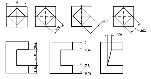
<Spacebar> and ![]() <T>. Presented below are several examples of dimensions that can be created between two lines or a line and a node. Parameter definition is described below, after the description of other dimension types.
<T>. Presented below are several examples of dimensions that can be created between two lines or a line and a node. Parameter definition is described below, after the description of other dimension types.
Let’s review the process of tying the dimension witness lines using the options ![]() <Spacebar> and
<Spacebar> and ![]() <T>. This process is optional and necessary only when the dimension entity strokes must be strictly tied to the construction elements in the drawing.
<T>. This process is optional and necessary only when the dimension entity strokes must be strictly tied to the construction elements in the drawing.
Example of option Tie Dimension to Node ![]() usage:
usage:
Let's create a dimension by two lines and press <T> once. The dimension will be fixed in the position next to the node. After that we move cursor up and create a leader line extension.
The Center Dimension Text ![]() option should be disabled.
option should be disabled.
If we press <T> one more time, the leader will be tied to the nearest node.

Example of option Place Dimension in absolute coordinates ![]() usage:
usage:
When you type <Spacebar> for the first time the dimension will be fixed at the specified distance from the object. If you move cursor up, create a leader line extension and press <Spacebar> again, a leader jog will be created.
If the Center Dimension Text ![]() option is enabled, the second spacebar pressing will create a leader line extension.
option is enabled, the second spacebar pressing will create a leader line extension.

The third subsequent use of the option <Spacebar> causes creation of the leader jog attached to the center of the leader line.
The fourth subsequent use of <Spacebar> will switch dimension into “invisible leader” mode. There will be no leader lines but text will remain and will behave like if it is located on a leader. This mode allows locating text in arbitrary place.

The fifth subsequent use of <Spacebar> reverts the dimension to the original state.
Note, that use of options <Spacebar> and <T> is recommended, when you want to strictly define the dimension position through parametric modifications of the drawing. When modifying positions of the nodes to which the dimension strokes are tied, the dimension position will be changing accordingly.
To break a tie to a node, use the option ![]() . If you click on the marker that indicates node to which the dimension is tied, the relation will be broken automatically and the option will not appear.
. If you click on the marker that indicates node to which the dimension is tied, the relation will be broken automatically and the option will not appear.

The option ![]() allows explicitly assigning the tying nodes for dimension strokes created on the construction lines (by default, the system selects the node on the selected line nearest to the dimension position). Suppose, the lower witness line in the first drawing is tied to the default node. Let's specify another tying node using the option <N>. The modified dimension is shown on the right hand side diagram.
allows explicitly assigning the tying nodes for dimension strokes created on the construction lines (by default, the system selects the node on the selected line nearest to the dimension position). Suppose, the lower witness line in the first drawing is tied to the default node. Let's specify another tying node using the option <N>. The modified dimension is shown on the right hand side diagram.

With the option ![]() turned on, the dimension text will be centered between the witness lines. Without the option, the dimension text is positioned wherever the mouse click occurred.
turned on, the dimension text will be centered between the witness lines. Without the option, the dimension text is positioned wherever the mouse click occurred.
The option ![]() allows quickly changing the dimension prefix symbol ("R", "Ж", "M", "", "o"), without calling the dimension parameters dialog box.
allows quickly changing the dimension prefix symbol ("R", "Ж", "M", "", "o"), without calling the dimension parameters dialog box.
When creating a dimension with a jog, the option ![]() (<Z>) will help changing the shape and position of the jog.
(<Z>) will help changing the shape and position of the jog.
Pressing ![]() (<Z>) results in a change of a quarter in which the dimension is drawn. In this case, the mouse should be pointing to the quarter where the dimension should be placed.
(<Z>) results in a change of a quarter in which the dimension is drawn. In this case, the mouse should be pointing to the quarter where the dimension should be placed.

Dimensions between two nodes
Creating a dimension between two nodes is mostly similar to creating a dimension between two lines. The exception is multiple possibilities for the witness line positions. These possibilities are shown on the diagram below.

To select nodes, use the option:
![]() <N> Select Node
<N> Select Node
If two nodes to be dimensioned are connected by a graphic line, the option ![]() is used. Upon calling the option, select the desired segment, and its end nodes will be automatically selected for dimension creation.
is used. Upon calling the option, select the desired segment, and its end nodes will be automatically selected for dimension creation.

To toggle through the various types of dimensions between two nodes, the option <M> is provided in the automenu:
![]() <M> Change Dimension Type
<M> Change Dimension Type

This option toggles the various dimension types. Besides, the desired dimension type can be selected from the pull-down list. The parameters of the dimension being created can be defined using the option:
![]() <P> Set Dimension parameters
<P> Set Dimension parameters
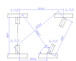
Angular Dimension by Four Nodes
Placing a dimension by four nodes represents itself basically a variation of the angular dimension between two segments (lines). The lines between which the dimension will be drawn are defined by the end nodes.
For drawing the dimension by four nodes the following option is used:
|
|
After choosing this option in the automenu, the option for selecting the nodes appears:
![]() <N> Select Node
<N> Select Node
Tooltips in the status bar show the order in which nodes are selected. The dimension will be tied to the first nodes of both lines.
After specifying all nodes, it is necessary to indicate location of the created dimension with the help of ![]() . While doing it, the following options will be available in the automenu:
. While doing it, the following options will be available in the automenu:
|
<P> |
Set dimension Parameters |
|
<Alt+P> |
Copy Properties from Existing Element |
|
<Z> |
Change leader line jog orientation |
|
<Shift+D> |
Select Linked Dimension |
|
<Z> |
Change Dimension Orientation |
|
<Spacebar> |
Place Dimension in absolute coordinates |
|
<T> |
Tie Dimension to Node |
|
<J> |
Center Dimension Text |
|
<K> |
Break relations (available if dimension is tied to the node) |
|
<Esc> |
Cancel selection |
The use of these options has been described above.
Linear Dimension by Three Nodes
Linear dimension by three nodes represents itself a variation of the linear dimension between a line (a segment) and a point. This means that the dimension will be drawn between the line defined by first two nodes (end points of the segment of the line) and the third node selected.
For drawing dimension by three points, the following option is used:
|
|
After choosing this option in the automenu, the option for picking the nodes appears:
![]() <N> Select Node
<N> Select Node
Tooltips in the status bar indicate the node selection order. After specifying all nodes, it is necessary to indicate the location of the dimension being created with the help of ![]() . While doing it, the following options are available in the automenu:
. While doing it, the following options are available in the automenu:
|
<Alt+P> |
Copy Properties from Existing Element |
|
<Shift+D> |
Select Linked Dimension |
|
<D> |
Change Sign |
|
<Spacebar> |
Place Dimension in absolute coordinates |
|
<T> |
Tie Dimension to Node |
|
<Z> |
Change leader line jog orientation |
|
<J> |
Center Dimension Text |
|
<K> |
Break relations (available if dimension is tied to the node) |
|
<Esc> |
Cancel selection |
The use of these options was described above in the section “Dimensions Between Two Straight Lines or Between a Line and a Node”.
Creating Arc Length Dimension
To dimension the length of a circular arc, use the option ![]() . The following items become available in the automenu after selecting the option:
. The following items become available in the automenu after selecting the option:
![]() <N> Select Node
<N> Select Node
![]() <Esc> Cancel selection
<Esc> Cancel selection
Dimensioning a whole arc starts with selecting an appropriate graphic entity.
In the case of dimensioning a portion of an arc or circle between two nodes, subsequently do the following:
1. Select the start node of the arc being dimensioned.
2. Select the end node of the arc being dimensioned.
3. Select the arc or circle passing through these nodes. An additional option is provided in the automenu:
![]() <C> Select Circle
<C> Select Circle
After selecting the arc by any means, the automenu provides the options:
|
<P> |
Set Dimension parameters |
|
<Alt+P> |
Copy Properties from Existing Element |
|
<Shift+D> |
Select Linked Dimension |
|
<Z> |
Change leader line jog orientation |
|
<Spacebar> |
Place Dimension in the absolute coordinates |
|
<J> |
Center Dimension Text |
|
<T> |
Tie Dimension to Node |
|
<K> |
Break relations (available if dimension is tied to the node) |
|
<H> |
Parallel/Radial Dimension Lines |
|
<Esc> |
Cancel selection |
As in the case of creating a dimension between two lines, the option <Spacebar> allows specifying the positions of dimension strokes. The option ![]() is used for tying the dimension to a node, while the option
is used for tying the dimension to a node, while the option ![]() - for breaking the tie. To set parameters of the dimension being created, use the option
- for breaking the tie. To set parameters of the dimension being created, use the option ![]() .
.
The option ![]() allows flipping the orientation of the dimension leader line jog.
allows flipping the orientation of the dimension leader line jog.
With the option ![]() turned on, the dimension text will be centered between the witness lines. With the centering off, the dimension text is position wherever the mouse click occurred.
turned on, the dimension text will be centered between the witness lines. With the centering off, the dimension text is position wherever the mouse click occurred.
Additionally, one can choose between the types of the dimension witness lines (parallel or radial) by using the options ![]() /
/![]() . To complete a dimension creation, click its position by
. To complete a dimension creation, click its position by ![]() . If the dimension is already tied to a node, clicking
. If the dimension is already tied to a node, clicking ![]() simply confirms its creation.
simply confirms its creation.

Creating dimension by cone
A dimension by cone is created based on two non-parallel graphic lines. The selected lines are considered silhouette edges of a cone (cone projection). In this case, the dimension measures the distance between the ends of the selected lines, in the direction orthogonal to the cone axis. Thus, one can dimension a cone base on a projection view without creating additional nodes at the line ends.
To create a dimension by cone, use the option ![]() . After selecting the option, the following items are available in the automenu:
. After selecting the option, the following items are available in the automenu:
![]() <G> Select line
<G> Select line
![]() <Esc> Cancel selection
<Esc> Cancel selection
The dimension creation starts with subsequent selection of two non-parallel graphic lines. Once the lines are selected, the following options appear in the automenu:
|
<P> |
Set Dimension parameters |
|
<Alt+P> |
Copy Properties from Existing Element |
|
<Shift+D> |
Select Linked Dimension |
|
<Z> |
Change leader line jog orientation |
|
<Spacebar> |
Place Dimension in the absolute coordinates |
|
<J> |
Center Dimension Text |
|
<D> |
Change Dimention Sign |
|
<M> |
Change Dimension type |
|
<T> |
Tie Dimension to Node |
|
<K> |
Break relations (available if dimension is tied to the node) |
|
<Esc> |
Cancel selection |
Line ends selection for attaching a dimension is done automatically by the system. However, if necessary, this can be modified using the option <M> (![]() ) that helps quickly toggle through all possible pairs of line ends.
) that helps quickly toggle through all possible pairs of line ends.
As in the case of creating a dimension between two lines, the option <Spacebar> allows specifying the positions of strokes of a dimension. The option ![]() is used for tying a dimension to a node, while the option
is used for tying a dimension to a node, while the option ![]() – for breaking such a tie. The option
– for breaking such a tie. The option ![]() serves for specifying dimension parameters.
serves for specifying dimension parameters.
The option ![]() allows flipping the dimension leader jog orientation, and the option
allows flipping the dimension leader jog orientation, and the option ![]() – quickly changing the dimension prefix (the default symbol is "D"). Centering dimension text is set by the option
– quickly changing the dimension prefix (the default symbol is "D"). Centering dimension text is set by the option ![]() .
.

Dimensioning a single graphic entity
To dimension a single graphic entity (a line segment or an arc), you do not have to call the option ![]() or
or ![]() . You can simply select a line segment or an arc by clicking
. You can simply select a line segment or an arc by clicking ![]() . Then, while still holding down the left mouse button, slightly move the pointer. The command will then automatically assume the mode of creating a line segment length or an arc dimension.
. Then, while still holding down the left mouse button, slightly move the pointer. The command will then automatically assume the mode of creating a line segment length or an arc dimension.
Creating dimension chains
The option ![]() allows creating dimension chains for a group of parallel lines, as well as appending dimensions to already existing chains. Upon selecting the option, the following icons become available in the automenu:
allows creating dimension chains for a group of parallel lines, as well as appending dimensions to already existing chains. Upon selecting the option, the following icons become available in the automenu:
|
<D> |
Select Dimensions in Chain |
|
<L> |
Select Line |
|
<N> |
Select Node |
|
<Bkspace> |
Сancel last element selection |
|
<Esc> |
Cancel selection |
To create a new dimension chain, select subsequently the construction lines, the graphic lines or the nodes to be dimensioned. Complete the entity sequence selection by pushing the option:
|
<E> |
End Dimension Chain input |
After that, the following options will appear in the automenu:
|
<P> |
Set Dimension parameters |
|
<Alt+P> |
Copy Properties from Existing Element |
|
<T> |
Tie Dimension to Node |
|
<K> |
Break relations (available if dimension is tied to the node) |
|
<Esc> |
Cancel selection |
The option ![]() help tying dimension position to a node, while the option
help tying dimension position to a node, while the option ![]() breaks this tie. To define parameters of a dimension being created, use the option
breaks this tie. To define parameters of a dimension being created, use the option ![]() .
.
To complete a dimension chain creation, specify its position by clicking ![]() . If the chain was tied to a node, then clicking
. If the chain was tied to a node, then clicking ![]() simply confirms the creation. Note that each dimension in the chain referencing a pair of lines, is a separate entity and can have its own parameters.
simply confirms the creation. Note that each dimension in the chain referencing a pair of lines, is a separate entity and can have its own parameters.

To add more dimensions to an existing chain of dimensions, upon calling the option ![]() select one of the dimensions in the chain to be appended. By doing so, you define the base for the dimensions to be created. The further steps will be similar to the previous case. The chains can have gaps. Should this be the case, select a line or node as the first entity of the chain continuation that is not referenced by the last existing dimension in the chain.
select one of the dimensions in the chain to be appended. By doing so, you define the base for the dimensions to be created. The further steps will be similar to the previous case. The chains can have gaps. Should this be the case, select a line or node as the first entity of the chain continuation that is not referenced by the last existing dimension in the chain.
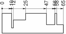
Creating Dimensions from One Baseline
The option ![]() serves for creating dimensions from one base. The creation procedure for this dimension type is mostly similar to the previous case (creating a chain of dimensions from the common base), except the number of additional features.
serves for creating dimensions from one base. The creation procedure for this dimension type is mostly similar to the previous case (creating a chain of dimensions from the common base), except the number of additional features.


The following items are available in the automenu after selection of lines and nodes for the dimension creation and pressing ![]() :
:
|
<P> |
Set Dimension’s Parameters |
|
<Alt+P> |
Copy Properties from Existing Element |
|
<Z> |
Hide Axis Origin |
|
<S> |
Sign of Dimensions’ Orientation |
|
<Space> |
Location Autocorrection Mode |
|
<M> |
Change Dimension’s Type |
|
<L> |
Value next to Leader/Value on Leader/Value on Leader inside Lines |
|
<T> |
Tie Dimension to Node |
|
<K> |
Break relations (available if dimension is tied to the node) |
|
<Esc> |
Cancel Selection |
The ![]() option allows us to display/hide zero tick mark for given dimension chain. When option
option allows us to display/hide zero tick mark for given dimension chain. When option ![]() is enabled, dimensions are drawn with the negative values of their values. This option works only dimensions that were created from top to bottom or from right to left.
is enabled, dimensions are drawn with the negative values of their values. This option works only dimensions that were created from top to bottom or from right to left.
Option ![]() /
/![]() /
/![]() is toggled cyclically and allows to choose variant of placement for dimensional size: nominal near jog/nominal at jog/nominal at jog inside lines.
is toggled cyclically and allows to choose variant of placement for dimensional size: nominal near jog/nominal at jog/nominal at jog inside lines.
|
|
|
Nominal near Jog |
Nominal at Jog |
Nominal at jog inside lines |
Dimensions from one base can be of two types: normal and ordinate. The dimension type can be modified either at the time of creation or at editing. This is done by the option:
|
<М> |
Change Dimension type |
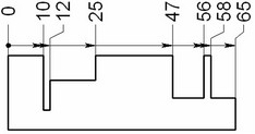
In the case of ordinate dimensions, only the witness lines are drawn, while the leader lines are not.
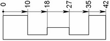
Normal dimension Ordinate dimension
![]() <Space> Leaders autocorrection
<Space> Leaders autocorrection
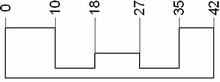
This option helps avoiding overlapping text of the dimensions from one base when those are placed near to each other. A jog is introduced in the dimensions that "creep" on the predecessors.
Autocorrection is off Autocorrection is on
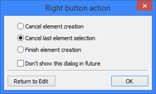
In the process of creating a dimension chain or base dimensions, pressing <Esc> or ![]() displays a dialog box for selecting the action to execute.
displays a dialog box for selecting the action to execute.
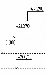
Creating Ordinate dimensions (level markers)
To create a construction dimension, use the option ![]() . Upon calling the option, the following icons become available in the automenu:
. Upon calling the option, the following icons become available in the automenu:
|
<D> |
Select ordinate dimension |
|
<L> |
Select Line |
|
<N> |
Select Node |
|
<Esc> |
Cancel selection |
Creating a series of dimensions from the same base starts with selecting the base ("zero") dimension. To do this, upon calling the option ![]() simply select a horizontal construction or graphic line, or a node. As a result, a dimension starts rubberbanding on the screen, following the pointer.
simply select a horizontal construction or graphic line, or a node. As a result, a dimension starts rubberbanding on the screen, following the pointer.

Meanwhile, the following options become available in the automenu:
|
<P> |
Set Dimension parameters |
|
<Alt+P> |
Copy Properties from Existing Element |
|
<Shift+D> |
Select Linked Dimension |
|
<Z> |
Change leader line jog orientation |
|
<T> |
Tie Dimension to Node |
|
<Ctrl+T> |
Link String to Node |
|
<K> |
Break relations (available if dimension is tied to the node) |
|
<Esc> |
Cancel selection |
As in the case of a normal dimension creation, the option ![]() flips the orientation of the dimension leader jog. The option
flips the orientation of the dimension leader jog. The option ![]() allows defining the positions of the dimension strokes by tying them to drawing nodes. In the letter case, use of the option <T> for the first time defines horizontal positioning, that is, the position of the vertical stroke of the dimension jog. The second use of the option <T> defines the dimension height, that is, the level of the horizontal stroke of the jog. To undo a tie, use the option
allows defining the positions of the dimension strokes by tying them to drawing nodes. In the letter case, use of the option <T> for the first time defines horizontal positioning, that is, the position of the vertical stroke of the dimension jog. The second use of the option <T> defines the dimension height, that is, the level of the horizontal stroke of the jog. To undo a tie, use the option ![]() . The dimension creation can be completed by pointing the mouse at the desired position and clicking
. The dimension creation can be completed by pointing the mouse at the desired position and clicking ![]() .
.
The thus created dimension becomes the base dimension. Meanwhile, the option of creating ordinate dimensions stays active, with the automenu providing the options for a line ![]() and node
and node ![]() selection. By selecting next horizontal line or node, you begin creation of another dimension relative to the base. It's creation steps are same as the described above. To complete creation of a series of base dimensions, return from the option
selection. By selecting next horizontal line or node, you begin creation of another dimension relative to the base. It's creation steps are same as the described above. To complete creation of a series of base dimensions, return from the option ![]() into the main command menu. On a subsequent call for the option, selecting a horizontal line or a node will create a new base, with the subsequently created dimensions referencing the new base.
into the main command menu. On a subsequent call for the option, selecting a horizontal line or a node will create a new base, with the subsequently created dimensions referencing the new base.
To create dimensions relative to an existing base, upon calling the option, select the desired base dimension, or a dimension referencing the base. All dimensions created thereafter will be referencing that base.
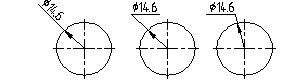
Dimensioning a circle
When dimensioning a circle, there is only one reference, which is the circle being dimension. After calling the command "D: Create dimension", point the mouse at the desired circle and click ![]() or <C>. The circle will be highlighted, and a radius or diameter dimension will start rubberbanding with the pointer.
or <C>. The circle will be highlighted, and a radius or diameter dimension will start rubberbanding with the pointer.

The following set of options will become available in the automenu:
|
<P> |
Set Dimension parameters |
|
<Alt+P> |
Copy Properties from Existing Element |
|
<Shift+D> |
Select Linked Dimension |
|
<Z> |
Change leader line jog orientation |
|
<Spacebar> |
Place Dimension in absolute coordinates |
|
<T> |
Tie Dimension to Node |
|
<D> |
Change Dimension Symbol |
|
<M> |
Change Dimension Type |
|
<Esc> |
Cancel selection |
The type of the dimension being created is chosen in the drop-down list of the option Change Dimension Symbol. The following types are available ![]() ,
, ![]() ,
, ![]() ,
, ![]() ,
, ![]() .
.
The type of the dimension may be selected from the drop-down list ![]() Change Dimension Type
Change Dimension Type ![]() ,
, ![]() ,
, ![]() . The list differ for the radial dimension
. The list differ for the radial dimension ![]() and includes the following options:
and includes the following options: ![]() ,
, ![]() ,
, ![]() .
.

Once the necessary settings are defined, the created dimension will appear on the drawing. Follows are some types of dimensions on a circle supported by the system.

Creating radial dimension with jog on leader line
For circles of a large radius, a radial dimension can be created with a jog on the leader line. To do this, use the option ![]() of the command top-level automenu. Upon calling the option, select the circle to be dimensioned. As a result, the select a circle will be highlighted and a dimension will start rubberbanding following the pointer. As the pointer moves, the end of the leader line and the whole dimension position will be adjusting accordingly. Meanwhile, the following options are available in the automenu:
of the command top-level automenu. Upon calling the option, select the circle to be dimensioned. As a result, the select a circle will be highlighted and a dimension will start rubberbanding following the pointer. As the pointer moves, the end of the leader line and the whole dimension position will be adjusting accordingly. Meanwhile, the following options are available in the automenu:
|
<P> |
Set Dimension parameters |
|
<Alt+P> |
Copy Properties from Existing Element |
|
<Shift+D> |
Select Linked Dimension |
|
<K> |
Break relations (available if dimension is tied to the node) |
|
<X> |
Create Group of Radial Dimensions |
|
<Esc> |
Cancel selection |
To create the dimension, move the pointer to position the dimension as desired, and click ![]() . In this case, the default size and position of the dimension jog are set.
. In this case, the default size and position of the dimension jog are set.

If necessary, the size and position of dimension components can be arbitrarily modified, including tying nodes.
Use special markers for this purpose. Upon selecting the circle, a fixation marker appears. You need to select a node to which the dimension will be tied.
After the dimension position selection, you may change the dimension leader jog position. Select the special marker on the dimension leader jog, press ![]() and move the cursor. The dimension leader jog will follow the cursor along the dimension line.
and move the cursor. The dimension leader jog will follow the cursor along the dimension line.

The additional option ![]() turns on the mode of continuous radius dimension creation at a common fixing point. This mode can be used for creating radius dimensions, originating at the same point, on several concentric circles. With the option on, upon completing one dimension creation (the one on the first circle), the system waits for dimensioning another circle.
turns on the mode of continuous radius dimension creation at a common fixing point. This mode can be used for creating radius dimensions, originating at the same point, on several concentric circles. With the option on, upon completing one dimension creation (the one on the first circle), the system waits for dimensioning another circle.

If the fixing point of the first circle dimension was tied to a 2D node, then the dimensions on all following circles are tied to this node automatically. However, if the first dimension was fixed arbitrarily, then a free node is created at that point, with all the rest of the dimensions tied to it.
Drawing Leader Dimension
For drawing dimension similar to one shown on the picture on the right, the option ![]() is used.
is used.
After calling this option, it is necessary to indicate the fixing point (2D node) for tying the dimension. In the automenu the following option for picking the node appears:
![]() <N> Select Node
<N> Select Node
After specifying the fixing point, it is necessary to specify location of the leader of the dimension. Dimension parameters are specified manually in the dialog of the command's properties or with the help of the option ![]() .
.
In addition, the following options are available in the automenu:
|
<P> |
Set Dimension parameters |
|
<Alt+P> |
Copy Properties from Existing Element |
|
<Shift+D> |
Select Linked Dimension |
|
<Z> |
Change leader line jog orientation |
|
<D> |
Change Sign |
|
<T> |
Tie Dimension to Node |
|
<Ctrl+T> |
Link String to Node |
|
<Esc> |
Cancel selection |
Creating dimensions from Axis
Diameter dimensions, which are created from the axis, look like standard linear dimensions with diameter sign and doubled nominal values set in their parameters. There is no arrow near axis; it is replaced with the outline with length half of the font size.

The ![]() option is used for creation of such dimensions. After activation, you should define axis for the dimension creation. The following option is used for this purpose:
option is used for creation of such dimensions. After activation, you should define axis for the dimension creation. The following option is used for this purpose:
|
<L> |
Select Line |
Straight construction or graphic line can be chosen as axis.
When axis was selected, you should define object for creation of the dimension. It can be a construction line, a graphic line or a 2D node. The following items become available in automenu:
|
<L> |
Select Line |
|
<N> |
Select Node |
After defining axis and object used for creation of dimension, it is necessary to set its location. Parameters of dimension can be set manually in the dialog box of the command properties or with the help of option ![]()
The following options are available in automenu:
|
<P> |
Set Dimension parameters |
|
<Alt+P> |
Copy Properties from Existing Element |
|
<Shift+D> |
Select Linked Dimension |
|
<Z> |
Change leader line jog orientation |
|
<Space> |
Place Dimension in absolute coordinates |
|
<J> |
Center Dimension Text |
|
<D> |
Change Sign (change prefix) |
|
<T> |
Tie Dimension to Node |
|
<K> |
Break relations (available if dimension is tied to the node) |
|
<Esc> |
Cancel selection |
Dimensions Between Two Circles
The command ![]() allows creating linear dimensions between two circles. After activation of the command, you need to select two circles between which the dimension will be created.
allows creating linear dimensions between two circles. After activation of the command, you need to select two circles between which the dimension will be created.
The following options are available in automenu:
|
<P> |
Set Dimension parameters |
|
<Alt+P> |
Copy Properties from Existing Element |
|
<Shift+D> |
Select Linked Dimension |
|
<Z> |
Change leader line jog orientation |
|
<Space> |
Place Dimension in absolute coordinates |
|
<J> |
Center Dimension Text |
|
<D> |
Change Sign (change prefix) |
|
<T> |
Tie Dimension to Node |
|
<Esc> |
Cancel selection |
There are three dimension types for non-coaxial circles dimensions:
●Distance between centers
●Distance between the closest points of the circles
●Distance between the farthest points of the circles
Use ![]() option to change the dimension types.
option to change the dimension types.
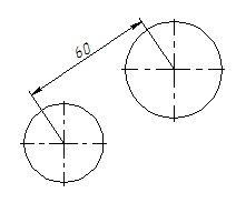


Difference of the radii is measured for coaxial circles. You can use special control marker on the larger circle to move dimension.

Dimension parameters
Dimension parameters are defined in the command's properties window before finishing dimension creation (or editing).
Dimension parameters are arranged by several sections in the properties window according to the parameter type. Depending on the type of the created dimension (angular, linear, radius, ordinate, arc length), the sets of parameters in the sections may vary.
«Value» section
Value. This group parameters determine, how the nominal dimension value will be defined. You can select the following choices from the drop-down list:
●Auto. The dimension value is calculated automatically based on drawing elements on which it is created. This allows a dimension to automatically change its value upon any modification to the drawing. The field on the right-hand side for the manual dimension value input is inaccessible.
●Manual. The dimension value is defined by the user manually in the input field at the right of the drop-down list. Regardless of drawing modifications, such dimension value will stay unchanged. This option is used when you need to introduce a dimension value in the drawing, that does not match the calculated dimension value.
●Manual with Corrections. The dimension value is specified manually by a user similar to the previous case. However, on the drawing the dimension value for the given dimension will be shown taking into consideration the specified scale and corrections (see below).
●By Source Lines. This option is available for 2D dimensions, drawn on the elements of any associative copy. Upon selection of this option, the dimension value is determined by the original elements of the copy (if for such dimension the case “Auto” is selected, then the value of the dimension is evaluated on the basis of those elements of the copy to which the dimension is tied to).
The option “By Source Lines” can be used, for example, for dimensioning on the lines of the associative copies (including the drawing views) without taking into account the scale of the copy.
●None. The dimension value string does not show on the dimension.
●From lines. This option is available for dimensions created manually on the 2D projection lines (or their associative copies) corresponding to the thread (special 3D operation created with the help of the command “3AT: Create Thread”). Also, this option is available for 3D dimensions drawn on the threaded surfaces of the 3D model.When selecting this option, the text displayed on the dimension originates from the thread parameters (that is, the thread notation is displayed instead of the dimension value string).

From 3D parent. This option is available only for dimensions created manually on the 2D projection lines (or their associative copies) and on condition that 3D dimensions are drawn on the corresponding to those lines faces, edges and vertexes of the original 3D model. Upon selection of this option, the text and parameters of the dimension will be inherited from the parameters of the 3D dimension.
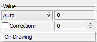
The inaccessible for editing field found below the group “Value” is informative. It shows how the dimension has been created and how its value and parameters have been determined:
●“On Drawing ” – standard 2D dimension drawn by nodes or by lines of a 2D drawing. The value of the dimension is evaluated by the geometry of the drawing or specified manually;
●“On Copy: On Drawing” – dimension is drawn on the elements of the associative copy of the nodes and the lines of a 2D drawing. Similar text string also appears if the dimension is drawn on the elements of the associative copy of the 2D projection lines, and for this dimension the field “Value” has an arbitrary value except “By Source Lines” (that is, the value of the dimension is determined either by the elements of the copy itself or specified manually);
●“On Copy: On Projection” – dimension is drawn on the elements of the associative copy of the 2D projection lines and for this dimension the field “Value” has the value “By Source Lines”. In this case, the value of the dimension is evaluated by original objects of the copy, i.e. by the 2D projection lines;
●“On Projection” – dimension is drawn on the 2D projection lines. If on the faces of a 3D model corresponding to given projection lines there is a 3D dimension, and for the 2D dimension the field “Value” has the value “From 3D parent”, then “(*3D)” is added to the information string;
●“On Operation” – this text string appears for 3D dimensions drawn on the vertexes, edges and faces of a 3D model (see the chapter “3D Annotations” of the manual on 3D modeling)
●“Projected” – this string appears for 2D dimensions created via the command of auto-dimensioning of 2D projections (see the chapter “3D Annotations” of the manual on 3D modeling).
Correction. This parameter defines the correction amount that will always be added to a dimension value. It is available only if the options “Auto” or “Manual with Correction” were chosen for specifying dimension value.
Please note that in the case when a scale is defined, the correction is added to the already scaled dimension value.
The info field at the end of the "Value" group indicates the position of the dimension placement: "On drawing" (for the dimensions created on common construction or graphic elements), "On projection" (for dimensions on 2D projections), "On operation" (for 3D dimensions).
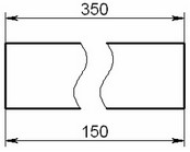
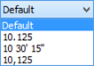
The "Scale" group serves to define the value of the scale factor. The scale factor provides control over the dimension value. For example, suppose, some portion of a drawing was performed to a different scale. Since the units are the same throughout the drawing, you shall specify a scale factor for the dimensions in the said portion of the drawing. Then the dimension value will be displayed according to the specified scale (that is, multiplied by the specified scale factor). The value of the scale is not taken into account if the parameter “Value” was set the value “Manual”.
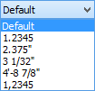
You can select the desired option from the drop-down list:
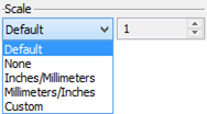
Default. The dimension value will be affected by the settings made on the "Dimensions" tab of the ST: Set Document Parameters command dialog.
None. The dimension doesn't have a scale factor.
Inches/Millimeters, Millimeters/Inches. These are the standard scale factors introduced for the user convenience. When selecting one of those items, the appropriate scale factor is set automatically to make the conversion to other units.
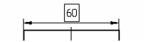
Custom. This option is used when it is necessary to set an arbitrary scale factor. The factor value is entered in the input field to the right of the drop-down list. For example, the case shown on the figure at the right has the, задан scale factor equal to "5" for both dimensions (the top dimension also having the correction of "100").
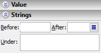
«Strings» section
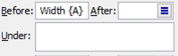
This section of the properties window collects the parameters that serve to define the text that shall be placed before, after or under the dimension value string.
Those strings can be defined manually, or substituted by numerical or text variables. Besides that, one can use all capabilities of text line formatting described in the "Text" chapter.
To insert a variable into one of the dimension strings, you need to enter its name in the respective string, surrounded in braces. For example, if you need to make the "A" variable value appear in the dimension text on the drawing, enter {A} in the respective dimension string.
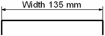
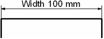
For example, in the string "Before" enter the desired text: width {A} mm
Note that the variable "A" is entered in braces. Suppose, its value is equal to 100. Set the parameter "Dimension text" (described above) to the value "No parameters". As a result, the dimension on the drawing will appear as shown on the diagram at the right.
For complete information on use of the variables, refer to the chapter "Variables".
Besides, special symbols can be entered in the text strings via <Alt><F9>. To do this, click inside a text string input box and press <Alt><F9>. Then, select the desired symbol and hit <Enter>.
Special symbols are various conventional textual and drawing notations. The symbols are represented by the textual font used in the parameter dialog box. On selecting a special symbol from the dialog box, it will be entered in the parameter string input box as a double percent character (%%) followed by the symbol code. However, upon placing the cursor into the parameter string which contains special symbols, a popup tooltip with a real image of the line contents will appear on the screen. On the drawing the special symbols will be also displayed precisely.
Note that the special symbols can be used as part of any parameter, which is a textual string, for various system elements.
String parameters of the dimension may be set using other parameters of the same dimension. You need to use $(VALUE) record, where VALUE – name of the parameter (as it is called in the PM: Measure operation)

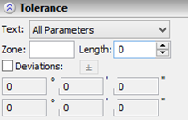
«Tolerance» section
This section of the properties window defines the tolerance zones and deviation limits.
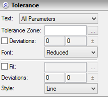
The "Text" parameter, which is coming first in the section, defines what parameters will be displayed together with the dimension nominal value:
Nominal. Only the dimension value is displayed |
|
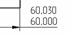
Limits (ANSI standard). The dimension value is composed of the two main values, each being the sum of the dimension value and the corresponding deviation limit. |
|
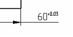
Nominal + Deviations. The deviation limits are displayed next to the dimension value. |
|
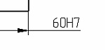
Nominal + Tolerance. The tolerance notation will be displayed next to the dimension value. |
|
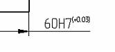
All parameters. In this case, both the tolerance notation and the deviation limits are displayed. |
|
No parameters. In this case, the dimension text is not displayed. This is convenient when the user intends to enter one's own text instead of the dimension value. |
|
Deviations can be defined manually or calculated automatically based on the specified tolerance zone. Automatic deviations calculation is used by default. The change from the manual setting to the automatic is done by toggling the "Deviations" flag (when the flag is off, the deviations are calculated automatically, when it is on – those are defined manually).
When using the automatic mode of calculating tolerances, you just need to specify the tolerance zone. Please note that the values of the calculated deviations depend on the measurement units defined in the ST: Set Document Parameters command menu. Automatic calculation of deviations works only for the millimeters or inches settings.
When the dimension value is modified, the deviations populated from tolerances will be adjusted automatically.
A variable can be entered in place of a deviation value just like in any other numerical field.
Various standards set the different requirements to the font size used to display value deviation limits in the drawing. Two choices are provided: reduced-height, which is half the font size, and full-height. To choose the desired one, use the "Font" parameter.
Fit parameters are defined similar to tolerance parameters.
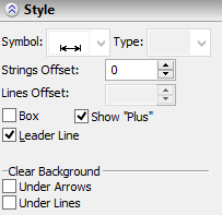
«Style» section
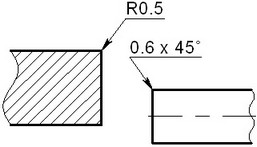
Sign. For a linear dimension, this parameter defines a special symbol to be displayed before the dimension value. This is necessary to create, for example, a radius, diameter or thread dimension.


This parameter is not available for the circular arc length dimension.

Type. This parameter is required if you need to have a linear dimension without extension (witness) lines (this is often used when creating dimensions from a centerline). This parameter can also be used to create one-sided dimensions (used for dimensioning on cut views or for dimensions on large-size parts).
Strings offset. This parameter defines the distance by which the dimension value string and the string beneath the dimension will be separated from the dimension line or from the leader jog (by default = 0).
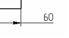
Lines offset. This parameter defines the offset of extension (witness) lines of a dimension from the object when creating dimensions per the ANSI and AR_ANSI standards. Whenever this parameter is not defined, the offset amount will depend on the size of the dimension line arrows.
The next diagrams correspond to the values of this parameter equal to "0" and "5".
![]()
![]()
Box. Turning on the "Box" flag outlines the dimension text by box.
Outside Arrows. When this flag is set, the dimension arrows are always drawn outside of the extension (witness) lines. When the flag is disabled (the default), the arrows position is determined automatically depending on the distance between the extension lines of the dimension. If arrows don't fit inside, then those will be automatically switched to outside.
Show when zero value. When this parameter is enabled, dimension will be displayed on the drawing even when its value is zero.
The "Clear Background" group provides controls for the dimension display mode in which drawing portions are erased around the dimension strokes:
Under Arrows. Turning on this item erases the drawing portions under and around the leader lines and leader arrows (at the distance equal to the thickness of the main continuous line).
Under Lines. Turning on this item erases the drawing portions under and around the witness lines (at the distance equal to the thickness of the main continuous line). In the case of the radial dimensions, the background is also erased under the cross marking the circle center.
«Arrows» section
In this section you define the type and size of arrows on either end of a dimension line. The value in square brackets means the arrow size will be per the value defined on the Lines > Arrow (End) Size tab of the ST: Set Document Parameters command dialog. Button |
|
«Units» section
Standard. This parameter allows selecting the dimension display standard: ANSI, AR_ANSI, ISO or Default. When the “Default” value is used, the dimension standard is copied from the parameter value in Dimensions > Standard of the ST: Set Document Parameters command.

![]()


Minimum Digits. This parameter determines the minimum number of decimal digits displayed in a dimension. For example, if the value “3” is specified, then the dimension 28.5 will be displayed as 28.500. If the “Default” is set, then the value is taken from the “Dimensions” tab of the ST: Set Document Parameters command.
Units. This defines the units in which the dimension value is displayed. Mostly, this item is important for inch dimensions. When the “Default” value is used, the dimension is displayed in the units defined in the ST: Set Document Parameters command.

Precision. Sets the rounding accuracy of dimension values. The accuracy "0.01" means the dimension values will be rounded to the second decimal digit. For example, if there is a dimension 28.4482, and the accuracy is 0.01, then the value 28.45 will be displayed in the drawing. If this item is set to Default, then its setting is defined on the «Dimensions» tab of the ST: Set Document Parameters command dialog.
«Alternative dimension» section
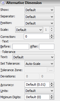
Show. This parameter determines the presence or absence of an alternative dimension in the drawing. When the parameter is set to "Default", then its setting is defined on the "Alternative dimensions" tab of the ST: Set Document Parameters command dialog.
Separator. This parameter sets the appearance of separators that are used in the drawing to separate the alternative and the main dimension values:
●Default. In this case, the separator assumes the type defined in the command ST: Set Document Parameters.
●None. The alternative dimension text will not be separated.
●[Brackets]. The alternative dimension text will appear in brackets.
●{Braces}. The alternative dimension text will appear in braces.
●(Parentheses). The alternative dimension text will appear in braces.
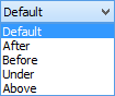
Position. This parameter defines the mode of displaying the alternative dimension value in the drawing at a relative location of the main dimension value. According to the choice made, the alternative dimension value will appear in the drawing "After", "Before", "Under" or "Above" the main dimension value string. If the parameter is defined as "Default", then its value is assumed from the "Alternative dimensions" setting of the command ST: Set Document Parameters.
Scale. This parameter defines the scale factor of an alternative dimension (which is fully analogous to the scale factor of the main dimension value).
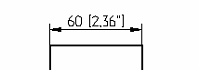
Why are «Alternative scale» and «Scale factor», respectively? Suppose, dimension values need to be created in two measurement systems at the same time, inches and metric. For this purpose, a special expression is introduced in the system - #DIM#. If this expression is used in any of the dimension lines (strings), then a dimension value will appear instead of it in the drawing, which will be multiplied by the alternative scale factor.
To follow the example on the right, set the «Alternative scale» to «Millimeters/Inches» and enter the following text in the «Text|After» field: [#DIM#%%119].
Correction. Parameter defines correction of the alternative dimension value compared to the calculated value. Correction is calculated similarly to the nominal value: displayed value = calculated value*scale factor + correction.
The "Text" group of parameters allows defining the text that will be displayed before or after the dimension value of an alternative dimension. Such strings can be entered manually or substituted by numerical or text variables. You can familiarize yourself with this capability in detail by reading the description of the counterpart parameter in the "String" section. If no parameter values are set in this group, then those are taken from the "Alternative dimensions" tab of the ST: Set Document Parameters command.
The "Tolerance" group of parameters allows defining tolerance zones (ranges) and value deviation limits of alternative dimensions:
Text. This parameter defines the included members of the dimension value string of an alternative dimension (the dimension value only, the dimension value with tolerance, etc.). A value can be selected from the list. The "Default" setting means the appearance of an alternative dimension will be determined by the "Text" parameter setting in the "Tolerance" section.
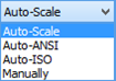
The tolerance zone is defined by the same-name parameter. The value deviation limits can be either defined manually (in the respective input fields) or calculated automatically. The method of defining deviations is controlled by the "Set Tolerance" parameter:
●Auto-Scale. The deviation limit values are calculated by the tolerance zone of the main dimension (while accounting for the measurement units of the alternative dimension – millimeters or inches). The definition of the tolerance zone value of an alternative dimension does not affect the calculation of its value deviation limits.
●Auto-ANSI. Deviations are calculated by the defined tolerance zone of an alternative dimension per the ANSI standard.
●Auto-ISO. Deviations are calculated by the defined tolerance zone of an alternative dimension per the ISO standard.
●Manually. The deviation values are defined by the user. Variables can be used instead of deviation values.
●When using the automatic modes of calculating deviations (Auto-Scale, Auto-ANSI or Auto-ISO), you just need to define the tolerance zone. The deviations will be calculated automatically.
Accuracy. Defines the rounding precision of the dimension values of the alternative linear dimensions. For example, the accuracy 0.01 means the dimension values will be rounded to the second decimal digit. Accuracy 0 means no rounding. If set to "Default", the accuracy assumes the settings from the "Alternative dimensions" tab of the ST: Set Document Parameters command.
Units. Defines the way of displaying the dimension values of alternative linear dimensions. This item is primarily used when working in inches. Just as in the previous case, the "Default" setting means the dimension will be displayed in the units defined on the "Alternative dimensions" tab of the ST: Set Document Parameters command.
Minimum Digits. This parameter determines the minimum number of decimal digits that is displayed for the alternative dimension value (similar to the "Minimum Digits" parameter of the main dimension value). If "Default" is set, then the value is taken from the "Alternative dimensions" tab of the ST: Set Document Parameters command.
«Options» section
The section contains only one auxiliary parameter– "Show Dialog for each Created Dimension". If this parameter is enabled, then the dimension parameters dialog will automatically appear after defining the dimension position in the dimension creation command (the option ![]() )
)

This mode allows working in the same way as in previous versions of T-FLEX CAD – by specifying the dimension position in the drawing first, and then defining its parameters.
Automatic alignment. If the option is enabled, the system automatically places the dimension number and the arrows outside when the dimension size is reduced to certain values.

Show toolbar with options. If the option is enabled, additional markers and options for will appear near dimension when you put cursor on it.

Special about defining angular dimension parameters
Linear and angular dimension parameters are mainly same. Described below are the existing differencies.
The set of tolerance parameters for angular dimensions is different from the respective parameters of other dimensions.
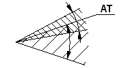
Since angular dimension tolerance calculation depends on the length, the parameter "Length" is provided for angular dimensions. When calculating deviations automatically, the following formula of defining the tolerance zone is used: +AT8, AT8 or -AТ8, where 8 is the tolerance grade, while a signed AT defines the tolerance type.
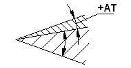
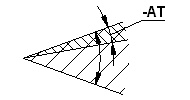
The deviations are calculated in degrees, minutes and seconds, respectively. The angular dimensions use special units for displaying the dimension value.
For angular dimensions you cannot specify an alternative scale, nor any other parameters related to an alternative dimension.
Special about defining parameters for dimensions on circles
The "Style" allows manipulating the display of the little cross at the center of the circle being dimensioned, (the parameter "Cross in center"). This is required by some standards. Otherwise, the parameters for circles correspond with the parameters for linear dimensions.
Special about defining parameters of orditate dimensions
Ordinate dimension parameters are mainly same as those of linear dimensions. Described below are the existing differencies.
The ordinate dimensions do not have the parameters to define tolerances and deviation limits. In the "Style" section there are only the parameters, whose status is relevant to an ordinate dimension. Besides, there are the following additional parameters:
Leader Line. Controls the leader extension creation between the dimension and the attachment node.
Show "plus". Controls the display of the "+" sign in dimensions with positive offset from the base dimension.
Just as for angular dimensions, there is no alternative scale for ordinate dimensions, nor any other parameters related to an alternative dimension.
Working with the dimension parameters dialog
You can also define dimension parameters in the parameters dialog called by the automenu option:
![]() <P> Set Dimension Parameters
<P> Set Dimension Parameters
The parameters located on the tabs of this dialog duplicate the parameters in the properties window. Besides that, the parameters dialog has a number of additional settings. First of all, that's the system-wise parameters: level, layer, priority and color. The parameters dialog also has an additional tab that contains the font settings. This tab is standard for various system elements (dimensions, annotation leaders, roughness symbols, GD&T formlimits). It allows defining all necessary font settings used to display the dimension value string. If the value of some of the parameters on the tab is set as "Default", then it will be taken from the "Font" tab of the ST: Set Document Parameters command dialog.
Parameters for new dimensions (default parameters)
The default parameters that will be applied to all newly created dimensions can be defined in a number of ways.
First of all, those can be defined within the parameters dialog (the option ![]() ). To do this, call the dialog before creating a dimension. The parameters defined for the new dimensions will be copied to the parameters set of each created dimension.
). To do this, call the dialog before creating a dimension. The parameters defined for the new dimensions will be copied to the parameters set of each created dimension.
You can also save the parameters defined when creating (or editing) a dimension, as the default parameters, by clicking the button ![]() in the command's properties window.
in the command's properties window.
Note, that the tab "Dimensions" of the command ST: Set Document Parameters defines only those of the described parameters, that have the default option. As a rule, all dimensions should appear consistently. Therefore, a good strategy is defining their appearance in the command ST: Set Document Parameters, while using the default settings for the parameters of a particular dimension. This allows instantly changing appearance of all dimensions, if necessary.
Besides the described parameters, the command ST: Set Document Parameters defines two more parameters. "Tolerance Grade" defines the threshold precision, up to which the dimension values are displayed on the drawing. This means, for dimensions, whose tolerance grade is less or equal to the specified, only the nominal values will be displayed.
The "Symbols" provides for defining codes of the selected special font, corresponding to the symbols diameter, degree, and "±" sign. This can be helpful when exporting files, and when using fonts that use different codes for these symbols.
Copying parameters from existing dimensions
Parameters of the dimension being created can be quickly copied from an already existing dimension. To do this, use the option:
![]() <Alt+P> Copy Properties from Existing Element
<Alt+P> Copy Properties from Existing Element
This option is available in the command automenu prior to creating the dimension or during the creation process (before selecting the dimension placement on the drawing).
After calling the option, simply pick the dimension whose parameters are to be transferred on the new dimension. The parameters will be copied that are common for both the selected dimension and the dimension being created.
To make the copied parameter values assigned to all newly created dimensions, before selecting the source dimension activate an additional option:
![]() <S> Set Properties as Default
<S> Set Properties as Default
With the option active, the copied parameters will be saved as default parameters.
This option simplifies creation of dimensions with identical parameters. However, it does not allow to copy specific parameters or parameters from an object of a different type. In such cases, more convenient could be using the general mechanism of editing element parameters in the property window.
Setting link of dimension with another dimension
For any type of dimension you create, it is possible to link it with the other already existing dimension by means of the following automenu option:
|
<Shift+D> |
Select linked dimension |
|
|
After calling this option, you must specify the dimension which parameters will be used for the dimension being created. When setting such link, parameters of "linked" dimension, for example, the nominal value, other display options, will be taken from the original dimension. List of "linked" parameters can be controlled in the properties dialog by selecting corresponding values for the nominal mode - “Auto”, “Manually”, “Manually+Corrections”, “From selected dimension”. If you do not want to display the content of "Before", "After" and "Under" strings of the linked dimension, it is necessary to remove the flag to "Project string ...". The flag appears when you put the mouse cursor over a field of the corresponding parameter. |
|
|||
To break the link between the dimensions you can use option:
|
<Shift+K> |
Break link with dimension |
Option is available only for the linked dimensions.
This functionality can be used, for example, to display dimensions on a simplified view with the same nominal values and other parameters as on the original accurate view.
Dimensions Alignment
The options group Dimensions Alignment is available in the context menu when you select several dimensions. The options allow associating the selected dimensions to move them together on the drawing.


The Group option creates group of dimensions. When you move one of the dimensions, the rest dimensions also move, maintaining its position, retaining their original position relative to each other.

The Delete Alignment option appears for grouped dimensions. The option cancels the alignment of all dimensions in the group.
The In Line option aligns all dimensions in one line. The option allows you to quickly build a chain of dimensions.

The Adjust with offset option allows you to align the dimensions vertically in accordance with the specified spacing.

The spacing between dimensions is specified in the ST: Set Document Parameters on the Dimensions tab using Alignment spacing parameter. The parameter specifies the spacing for newly created groups of dimensions and does not affect spaces of the already created groups.
When you create a new dimension above or under another dimension, a snap in accordance with a predetermined alignment spacing is active.
The following options are available in the context menu for each of the dimensions in the group:

The same options are in the automenu of the Edit command for the dimension.

![]() Move with others. The selected dimension is moved with the other dimensions in the group. The option is enabled by default.
Move with others. The selected dimension is moved with the other dimensions in the group. The option is enabled by default.
![]() Move relative to others. After activation of this option, the selected dimension can be moved relative to other dimensions in the group. After that, the dimension will move with other dimensions again, but the new position will be preserved.
Move relative to others. After activation of this option, the selected dimension can be moved relative to other dimensions in the group. After that, the dimension will move with other dimensions again, but the new position will be preserved.
![]() Exclude from alignment. The selected dimension is excluded from the alignment.
Exclude from alignment. The selected dimension is excluded from the alignment.
![]() Change Direction. Changes the position of the dimensions relative to the selected dimension. If the remaining dimensions in the group are located above the selected dimension, then they will be located below after activation of the option and vice versa.
Change Direction. Changes the position of the dimensions relative to the selected dimension. If the remaining dimensions in the group are located above the selected dimension, then they will be located below after activation of the option and vice versa.

Editing dimensions
Dimension editing is done via the command "ED: Edit Dimension":
Keyboard |
Textual Menu |
Icon |
<ED> |
"Edit|Draw|Dimension" |
|
Upon calling the command, the following options become available:
![]() <Enter > Select dimension
<Enter > Select dimension
![]() <*> Select All Elements
<*> Select All Elements
![]() <Esc> Exit command
<Esc> Exit command
Select a dimension for editing by pointing and clicking the mouse ![]() . That highlights the dimension. This dimension parameters will be displayed in the properties window. Meanwhile, the automenu offers the following options:
. That highlights the dimension. This dimension parameters will be displayed in the properties window. Meanwhile, the automenu offers the following options:
|
<P> |
Set selected Element(s) parameters |
|
<Alt+P> |
Copy Properties from Existing Element |
|
<O> |
Create Name for Selected Element |
|
<Shift+D> |
Select Linked Dimension |
|
<Shift+K> |
Break Link with Dimension |
|
<Z> |
Change leader line jog orientation |
|
<Z> |
Change Dimension orientation (for angular dimension) |
|
<Spacebar> |
Place Dimension in the absolute coordinates |
|
<J> |
Center Dimension Text |
|
<D> |
Change Dimension Symbol |
|
<T> |
Tie Dimension to Node |
|
<Ctrl+T> |
Link String to Node |
|
<N> |
Select insertion Node |
|
<W> |
Move dimension |
|
<M> |
Change Dimension type |
|
<H> |
Change Dimension Symbol |
|
<K> |
Break relations |
|
<D> |
Change Dimension Type |
|
<I> |
Select Other Element |
|
<Del> |
Delete selected Element(s) |
|
<Esc> |
Cancel selection |
Availability of some of the above options in the automenu depends on the ways of creation and the type of the selected dimension.
The selected dimension can be moved, tied to other drawing elements or have its parameters modified, with respect to the original settings. To do this, select the appropriate option in the automenu.
The option ![]() allows you to modify orientation of the leader extension of the dimension text.
allows you to modify orientation of the leader extension of the dimension text.
The option ![]() changes orientation of angular dimension (i.e., the quarter of an angle on which the dimension is drawn).
changes orientation of angular dimension (i.e., the quarter of an angle on which the dimension is drawn).
The option ![]() sets the mode of centering the dimension text. When pushed, the dimension text will be automatically centered between the witness lines.
sets the mode of centering the dimension text. When pushed, the dimension text will be automatically centered between the witness lines.
The option ![]() helps quickly changing the dimension value prefix ("R", "Æ", "M","", "o"), without calling the dimension parameters dialog box. The option
helps quickly changing the dimension value prefix ("R", "Æ", "M","", "o"), without calling the dimension parameters dialog box. The option ![]() serves for changing the reference elements (lines, nodes) of the dimension being edited. The fixing position of the dimension created using the option
serves for changing the reference elements (lines, nodes) of the dimension being edited. The fixing position of the dimension created using the option ![]() , can be changed by selecting two nodes.
, can be changed by selecting two nodes.
Sometimes, it is necessary to change the witness line attachment point. To do this, select the dimension at the point of the intended origin node of the witness line, and pick the option ![]() .
.
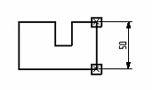
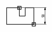
If a wrong dimension was selected, alter the selection using the option ![]() . The option
. The option ![]() or
or ![]() /
/![]() , depending on dimension type, allows changing its type without altering its references.
, depending on dimension type, allows changing its type without altering its references.
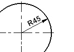
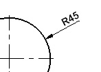
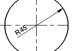
Note that if the dimension was tied to a node using the option ![]() , then to modify its fixing condition, first use the option
, then to modify its fixing condition, first use the option ![]() .
.
Option ![]() is used to assign a name to the selected dimension. The name is unique and allows you to uniquely identify this dimension.
is used to assign a name to the selected dimension. The name is unique and allows you to uniquely identify this dimension.
A selected dimension can be deleted using the option ![]() . Deleting chain dimensions or dimensions from one base can be done separately for each dimension. Deleting the parent dimension (which is the dimension between the first two lines) causes deletion of the whole dimension group. The same rule is used for ordinate dimensions, created on one base: any dimension in the series, except the base one, is deleted as a separate entity; when deleting the base dimension, all dependent dimensions are also deleted.
. Deleting chain dimensions or dimensions from one base can be done separately for each dimension. Deleting the parent dimension (which is the dimension between the first two lines) causes deletion of the whole dimension group. The same rule is used for ordinate dimensions, created on one base: any dimension in the series, except the base one, is deleted as a separate entity; when deleting the base dimension, all dependent dimensions are also deleted.
As in the case of other elements, multiple selection is done by the option ![]() , or using box selection or clicking
, or using box selection or clicking ![]() while holding down the <Shift> key (for adding to the list of selected) or <Ctrl> (for excluding from the list of selected).
while holding down the <Shift> key (for adding to the list of selected) or <Ctrl> (for excluding from the list of selected).
For editing parameters of a group of selected dimensions, use the option:
![]() <P> Set selected Element(s) parameters
<P> Set selected Element(s) parameters
First, select the set of parameters to be modified, in the dialog box that comes up on the screen. The standard dimension parameter dialog box will follow, allowing to define new parameter values. To define color, later, level and priority, one can also use the system toolbar. The option ![]() helps copying parameters from another existing dimension.
helps copying parameters from another existing dimension.
Remember, that a number of dimension settings are defined by default, which can be changed in the command ST: Set Document Parameters.
One can also enter the dimension editing command directly from the command "D: Create dimension", using the option:
![]() <F4> Edit Dimension
<F4> Edit Dimension
The third way of selecting a dimension for editing is available, when the system is in the command-waiting mode. Move the pointer over the dimension to be modified, and click ![]() . As a result, editing of the selected dimension begins. Besides, one can select the dimension and right click
. As a result, editing of the selected dimension begins. Besides, one can select the dimension and right click ![]() . The coming up context menu provides the commands for editing, deleting and modifying properties of the selected dimension.
. The coming up context menu provides the commands for editing, deleting and modifying properties of the selected dimension.
Working with dimensions in the 3D window
When using the 3D version of the system, you can create dimensions, just as well as leader notes and roughness symbols, in the 3D window, on the faces of the 3D model. This allows you to create fully functional three-dimensional drawings.
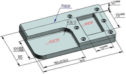
The parameters of such dimensions are automatically passed to the dimensions created in the 2D window on the respective lines of a 2D projection of a given model.
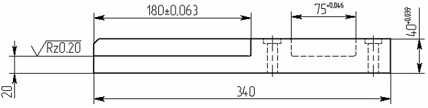
3D dimensions can serve as driving ("control") dimensions for 3D operations or construction elements. That means, when a dimension's nominal value is modified, the respective parameters of the operation or 3D construction element adjust to the change automatically.
You can also use the dimensions corresponding to the driving ones that are created on 2D projections, in order to modify the values of operation parameters. The system will match such pairs of dimensions automatically.
The detailed description of creating 3D dimensions and dimensions on projections is provided in the chapters "3D Annotations" and "2D Projections. Creating Drawings from 3D Models".