From Drawing to 3D Model Approach |
  
|
From Drawing to 3D Model Approach |
|
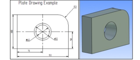
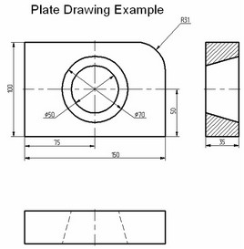
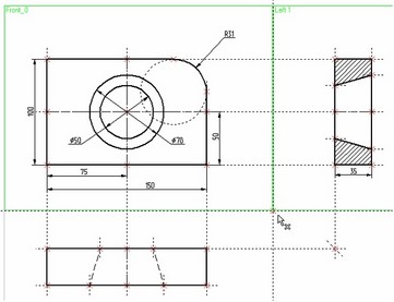
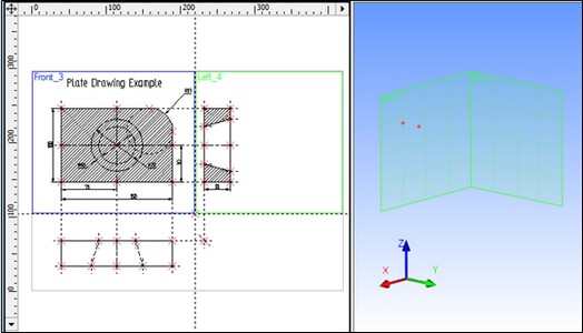
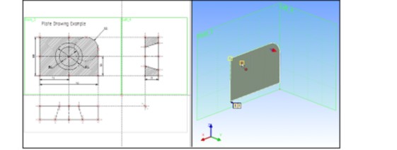
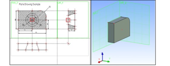
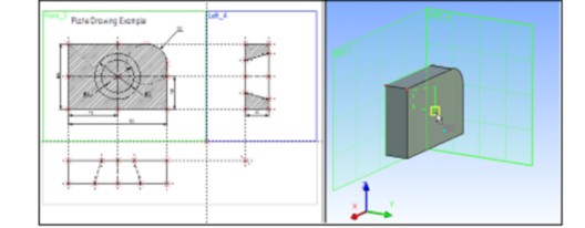
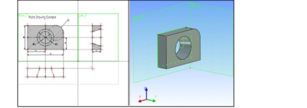
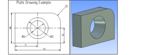
Let's create a 3D model from a 2D drawing. The model will be based on the familiar drawing of a plate with a conical hole. This drawing creation was reviewed in details within the brief introductory course of 2D design. The following diagram presents the 2D drawing and the 3D model of the plate to be created.
The drawing documents are located in the library “T-FLEX Parametric CAD 15 x64\Libraries\Examples\Documentation examples. Introductory course\Detail with drawing detailing; Step 1. Plate drawing; Step 2. Hatch and Profile; Step 3. Extrusion; Step 4. Rotation; Step 5. Boolean operation”.
We will pass through several design steps in order to create the 3D model of the plate. The first design step includes creation of the workplanes that will further be used for all the rest of 3D element construction. In the second step, we will perform extrusion of the defining contour of the plate at the specified depth in order to obtain the three-dimensional body of the plate. This will be done by extrusion operation. The next design step is creation of the tool body for the conical hole. We will create it using rotation operation. Finally, we will use Boolean operation in order to create the three-dimensional model of the plate in its final shape. We will subtract the second, tool body, created by rotation operation, from the original body created by extrusion.
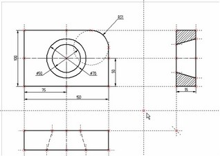
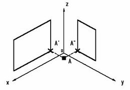
The first step in 3D model creation will be creation of the workplanes, as was mentioned earlier. Note that the workplanes should be constructed in such a way to maintain projective relationship between the views.
If not explicitly defined within the drawing, the projective relationship between the views can be established by fitting the drawing with associative auxiliary construction.
The 3D model creation process requires two workplanes. Let's begin with creating a 2D node defining the separation point of the views. To make the node, first create two orthogonal lines. Place these lines as shown on the diagram below.
Then create the workplanes.
Call the command
Icon |
Ribbon |
|---|---|
|
3D Model→ Construct → Model |
Keyboard |
Textual Menu |
<3W> |
Construct > Workplane |
Set the automenu option
![]() <S> Construct standard Workplane
<S> Construct standard Workplane
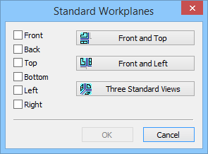
In the coming dialog box, press the button [![]() Front and Right]
Front and Right]
The cursor on screen gains the node mark ![]() . This mark means the system is now in selection mode. Move the cursor to the newly created node to be used for workplane snapping, and click
. This mark means the system is now in selection mode. Move the cursor to the newly created node to be used for workplane snapping, and click ![]() or type <N> key. Two horizontal workplanes will be created on screen for the main (elevation) and the left side view.
or type <N> key. Two horizontal workplanes will be created on screen for the main (elevation) and the left side view.
Then quit the command by clicking ![]() or pressing
or pressing ![]() icon in the automenu. One can also type the <Esc> key.
icon in the automenu. One can also type the <Esc> key.
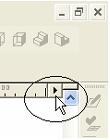
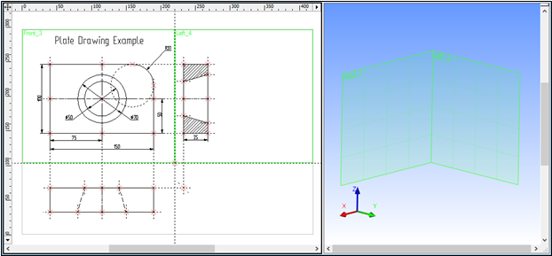
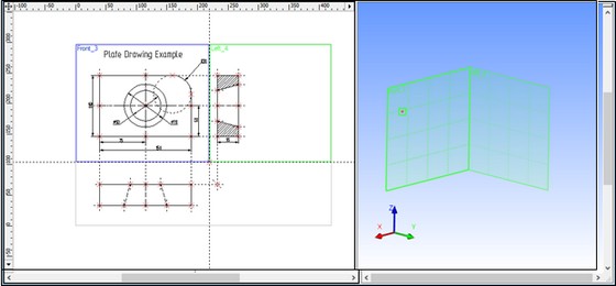
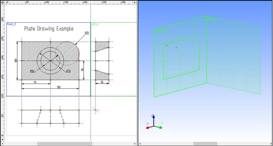
Now we can proceed with creation of 3D auxiliary elements. First, open the 3D view window of the T-FLEX CAD 3D system. The 3D view can be opened by clicking on a button with a triangular arrow in either the top-right or the bottom-left corner of the current drawing window next to the scroll bars. Place the cursor over such a button in the top-right corner, and click on it with ![]() . The current drawing window will be split vertically into two windows. One of the windows will be displaying the two-dimensional drawing, while the other, 3D view one, reflect the three-dimensional elements and bodies as they appear in the process of the 3D model creation.
. The current drawing window will be split vertically into two windows. One of the windows will be displaying the two-dimensional drawing, while the other, 3D view one, reflect the three-dimensional elements and bodies as they appear in the process of the 3D model creation.
Set the workplanes property "Show in 3D View" in order to have them displayed in the 3D window. To do it, it is necessary to select these planes in the tree of the 3D model, call the context menu with the help of ![]() and invoke the command “Parameters” in it.
and invoke the command “Parameters” in it.
To create the main body of the 3D model of the plate, extrude the perimeter contour at the length equal to the plate depth. To define the extrusion based on the existing 2D drawing, we need to create auxiliary 3D elements: a 3D profile and 3D nodes in a special way.
Let's create 3D nodes using existing 2D nodes and the workplane mechanism. To create a 3D node, one can specify either one node on one workplane, or two nodes on two different workplanes. In the latter case, the two nodes must be relatively located as two projections on their respective workplanes of one would-be 3D node.
Call the command:
Icon |
Ribbon |
|---|---|
|
Draw → Construct → 3D Node |
Keyboard |
Textual Menu |
<3N> |
Construct > 3D Node |
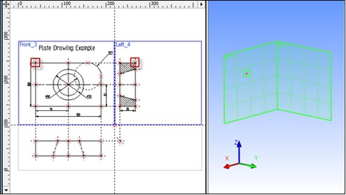
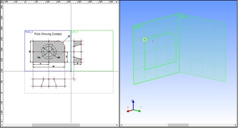
Next, proceed with selecting 2D nodes. Move the cursor to a node of the first projection of the would-be 3D node and click ![]() as shown on the diagram below. The 2D node and its workplane will get highlighted.
as shown on the diagram below. The 2D node and its workplane will get highlighted.
Normally, upon entering a 3D command, the system expects further user actions. Depending on these actions, the system assumes one or another specific mode. This mode usually depends on what kind of object was selected by user. The necessary options may automatically be set in the automenu depending on the user actions and the specific mode. The user can simply proceed with a predefined sequence of actions following the prompts in the status bar.
Once the first 2D node is selected, the system automatically turns on node creation by two projections:
![]() <J> Create 3D Node by two projections
<J> Create 3D Node by two projections
Once this mode is on, the user will be subsequently prompted to select the first, then the second projection 2D node, on and on, as he keeps selecting:
![]() <F> Set 3D Node 1st projection
<F> Set 3D Node 1st projection
![]() <G> Set 3D Node 2nd projection
<G> Set 3D Node 2nd projection
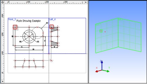
Move the cursor to the second node, representing the second projection of the 3D node, and click ![]() . The 2D node and the respective workplane, where the selection occurs, will get highlighted.
. The 2D node and the respective workplane, where the selection occurs, will get highlighted.
Confirm the 3D node creation by pressing ![]() icon in the top portion of the automenu. The 2D drawing elements get de-highlighted, and the newly constructed 3D node appears on the 3D scene.
icon in the top portion of the automenu. The 2D drawing elements get de-highlighted, and the newly constructed 3D node appears on the 3D scene.
Remember that some 3D commands are inaccessible while the 2D view of the current drawing is active. To make these commands accessible, activate the 3D view window. To do so, click ![]() anywhere within the 3D view window. Switching from 3D view back to 2D view is done in the same way.
anywhere within the 3D view window. Switching from 3D view back to 2D view is done in the same way.
Let's create the second 3D node. We are still within the command "3N: Construct 3D Node". Construct the second 3D node. To do so, we need to select two nodes as shown on the diagram below.
To confirm the second 3D node creation, press the ![]() icon in the automenu and exit the command. Two 3D nodes will be displayed in the 3D window.
icon in the automenu and exit the command. Two 3D nodes will be displayed in the 3D window.
The next step is creation of a 3D profile. We need to establish a relationship between the profile and the drawing. Drawing on the active workplane is not available to us since there is more than one workplane on one drawing page. Therefore, we will proceed with the 3D profile construction based on a hatch and a workplane. First, let's create the hatch.
Enter the command "H: Create Hatch". Create a hatch А on the elevation view. The hatch can be made invisible by setting the "Fill method" attribute of the hatch parameters to "Not Visible" mode. This is necessary for preserving the original look of the part drawing.
Now call the command
Icon |
Ribbon |
|---|---|
|
3D Model → Construct → 3D Profile |
Keyboard |
Textual Menu |
<3PR> |
Construction >3D Profile |
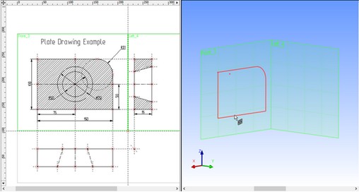
The system waits for further user action. Select the hatch À in the 2D window. The contour of the selected hatch and the workplane will get highlighted, and the respective profile will appear in the 3D window.
Once the hatch is selected, the system enters the mode for constructing a profile based on a hatch, and the following option activates in the automenu:
![]() <M> Select 3D point for fixing Profile plane
<M> Select 3D point for fixing Profile plane
The 3D node mark ![]() appears next to the cursor. Use the cursor to select one of the 3D nodes in the 3D view window. The profile will relocate to pass through the selected 3D node. The node itself and all its 2D and 3D construction references will be highlighted.
appears next to the cursor. Use the cursor to select one of the 3D nodes in the 3D view window. The profile will relocate to pass through the selected 3D node. The node itself and all its 2D and 3D construction references will be highlighted.
Confirm the 3D profile creation by pressing the ![]() icon in the automenu. All elements in either window will then be de-highlighted. We have just created a 3D profile. Quit the command to continue.
icon in the automenu. All elements in either window will then be de-highlighted. We have just created a 3D profile. Quit the command to continue.
All auxiliary 3D elements have been constructed that are required for a three-dimensional body creation by extrusion.
Let's create an extrusion operation:
Icon |
Ribbon |
|---|---|
|
3D Model → Create → Extrusion |
Keyboard |
Textual Menu |
<3X > |
Operation > Extrusion |
The following option will be set in the automenu by default,
![]() <R> Select Contour
<R> Select Contour
As we are to use the just created profile as the contour, let's set up the filters for 3D profile selection. This can be done on the system toolbar by ![]()
![]() on the desired filter icon as well by clicking
on the desired filter icon as well by clicking ![]() while holding the <Ctrl> key. All the rest of the filters will get turned off.
while holding the <Ctrl> key. All the rest of the filters will get turned off.
![]()
Move the cursor to the 3D window, place it by the profile and point at an edge of the profile. The cursor will gain a mark ![]() . Click
. Click ![]() to select the profile. The profile will be highlighted in the 3D window.
to select the profile. The profile will be highlighted in the 3D window.
Keep in mind that selection of 3D elements required by 3D commands can be performed either in the 3D, or in the 2D view window. This is especially relevant to selection of 3D nodes and 3D profiles (contours) that can be selected in the 2D view as nodes and hatches respectively.
Next, we need to specify direction and the depth of the extrusion. In this example, the depth of the extrusion is equal to the thickness of the plate. This dependency can be maintained if the extrusion vector is defined based on the existing 3D nodes.
Once the 3D profile is selected, turn on the following option in the automenu,
![]() <F> Select starting Point of Extrusion
<F> Select starting Point of Extrusion
Several views of the object can be used for specifying a 3D point. Make sure of the correct selection filter settings for 3D node selection on the system toolbar or in the pull-down list of active options.
As the cursor is pointed at a 3D node, it gets the node mark ![]() . Select the 3D node, which the 3D profile plane is passing through.
. Select the 3D node, which the 3D profile plane is passing through.
After selecting the first 3D node, another option will be automatically turned on in the automenu,
![]() <S> Select ending Point of Extrusion
<S> Select ending Point of Extrusion
Select the second 3D node with the cursor (point and click ![]() as usual). The preview of the current extrusion operation will appear on screen in wireframe mode.
as usual). The preview of the current extrusion operation will appear on screen in wireframe mode.
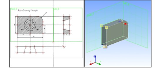
Press the ![]() icon, thus completing the extrusion operation.
icon, thus completing the extrusion operation.
Quit the command.
To create a hole in the three-dimensional model of the plate, we need to create the second 3D body. The latter will be used in the next step as the tool body for Boolean subtraction from the original extrusion. The 3D model of the hole is easiest to create by rotation operation.
To create a three-dimensional model by rotation, we need to define auxiliary 3D elements: the 3D profile and the axis of revolution for rotating the profile. To create the axis, we will need to construct 3D nodes.
Begin construction by calling the command "3N: Construct 3D Node". Enter the command, and select a 2D node as shown on the diagram below, by pointing and clicking ![]() . A highlighted 3D node will appear in the 3D window.
. A highlighted 3D node will appear in the 3D window.
Next, move the cursor to the second 2D node, defining the second projection of the 3D node, and click ![]() . The highlighted 3D node in the 3D window will move along the Y-axis.
. The highlighted 3D node in the 3D window will move along the Y-axis.
Confirm 3D node creation by pressing ![]() icon in the automenu. Highlighting turns off in both windows.
icon in the automenu. Highlighting turns off in both windows.
Create the second 3D node. It is necessary for defining the axis of revolution. The system is still within the command "3N: Construct 3D Node". Go ahead with the second 3D node creation. Do this by selecting two 2D nodes as shown on the following diagram.
After the final selection press the ![]() icon in the automenu, and quit the command.
icon in the automenu, and quit the command.
The next step is creation of the 3D profile.
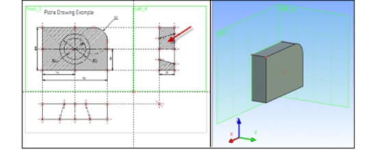
Create a hatch  on the side view of the 2D drawing using the "H: Create Hatch" command. Make the hatch invisible to keep the actual drawing legible.
Call the command "3PR: Construct 3D Profile".
Use the cursor to select the hatch В. The selected hatch contour and the workplane will get highlighted, and a 3D profile appear in the 3D window.
Once the hatch is selected, the cursor will gain the 3D node mark ![]() prompting the user for selecting a 3D node for locating the contour plane in space. Use cursor to select one of the 3D nodes in the 3D window. The profile will snap to the selected 3D node.
prompting the user for selecting a 3D node for locating the contour plane in space. Use cursor to select one of the 3D nodes in the 3D window. The profile will snap to the selected 3D node.
Confirm 3D profile construction by pressing the ![]() icon in the automenu.
icon in the automenu.
The profile is now created. To continue with the three-dimensional model creation, quit the command.
We have created all required auxiliary 3D elements for creating the three-dimensional body by rotation operation.
Let's create the rotation operation.
Call the command
Icon |
Ribbon |
|---|---|
|
3D Model → Create → Rotation |
Keyboard |
Textual Menu |
<3RO> |
Operation > Rotation |
Once within the command, the following default option is set in the automenu,
![]() <R> Select Contour
<R> Select Contour
Various elements can be used as a contour for rotation operation. We will use a 3D profile created specifically for this purpose. Before selecting a profile, check on the system toolbar or in the pull-down list that the selector filters are set correctly.
As the cursor approaches the 3D profile, it gains the profile mark ![]() . To select the profile, click
. To select the profile, click ![]() . The profile will be highlighted in the 3D window.
. The profile will be highlighted in the 3D window.
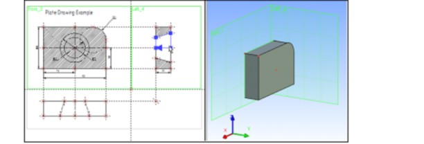
Next, define the axis of revolution by selecting two 3D nodes.
Set the following option in the automenu,
![]() <F> Select 1st Point of axis
<F> Select 1st Point of axis
Move the cursor to a 3D node as shown below, and click ![]() .
.
The option will activate in the automenu thereafter:
![]() <S> Select 2nd Point of axis
<S> Select 2nd Point of axis
Move the cursor to the second 3D node defining the axis of revolution, and click ![]() . The body to be created will appear as a wireframe preview in the 3D window. The icon
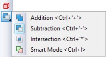
. The body to be created will appear as a wireframe preview in the 3D window. The icon ![]() becomes accessible in the automenu, meaning that the rotation operation can now be completed. Before finishing operation, you need to choose «Subtraction» from Boolean operation pull-down list.
becomes accessible in the automenu, meaning that the rotation operation can now be completed. Before finishing operation, you need to choose «Subtraction» from Boolean operation pull-down list.
|
<Ctrl><-> |
Substraction |
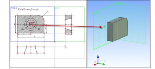
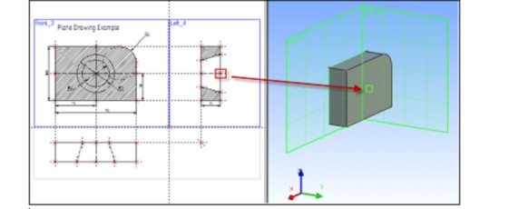
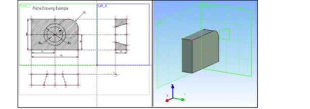
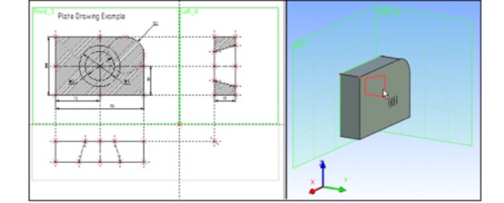
Confirm rotation by pressing ![]() icon in the automenu. The following three-dimensional image will appear in the 3D view window.
icon in the automenu. The following three-dimensional image will appear in the 3D view window.
We have just created two simplest 3D bodies, an extrusion and a body of revolution. Tool body of revolution was subtracted from the original extruded plate.
You can find more information about Boolean operations in the chapter “Boolean operation”.
In the three-dimensional model creation, we were using two-dimensional parametric elements of the T-FLEX CAD system as references. Therefore, parametric modifications of the two-dimensional drawing will drive parametric modifications of the three-dimensional model.
Modify one or more dimensions on the 2D drawing using the command "EC: Edit Construction", or "V: Edit Variables".
Then call the command
Icon |
Ribbon |
|---|---|
|
View toolbar → |
Keyboard |
Textual Menu |
<3G> |
Tools > Regenerate |
This will cause recalculation of the 3D model geometry, and the model will adjust to the latest modifications made on the 2D drawing.