Main Approach to 3D Model Creation |
  
|
Main Approach to 3D Model Creation |
|
In this chapter, you will learn how to create a three-dimensional model using simple examples. The manual describes all necessary steps in the modeling process. Further, you will learn the basic commands and principles of creating a 3D model.
T-FLEX CAD system allows various approaches to creating a 3D model. The main method is creating most of constructions directly in the 3D window. In another approach, a 3D model is created based on already prepared 2D drawings or auxiliary 2D constructions. This construction may further be used for generating drawings by projecting the model in all necessary views and making cuts and sections. These 2D objects can further be furnished with necessary dimensions and other drawing attributes.
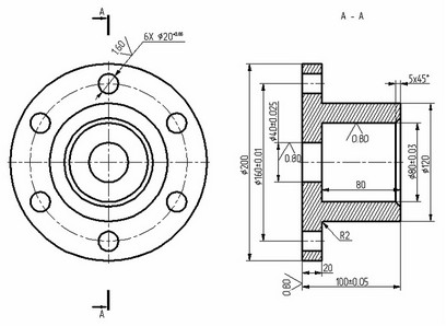
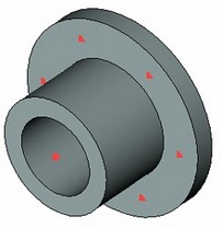
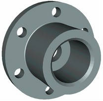
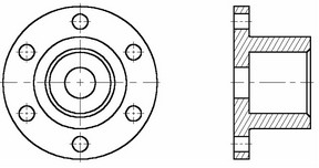
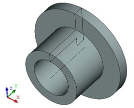
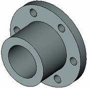
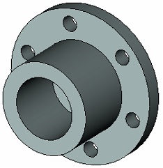
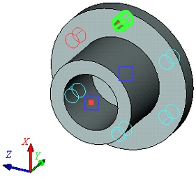
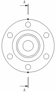
As mentioned above, this approach makes possible creating a three-dimensional model without using the 2D window. The diagram below shows a sample part that we will be modeling. We will create the three-dimensional model first, and then automatically generate views and a section.
The model file is located in the folder “T-FLEX Parametric CAD 15 x64\Libraries\Examples\Documentation Examples.Introductory course\Detail with drawing detailing”.
The model creation will be done in several steps. First, one has to create initial auxiliary elements. Based on those, you will be able to create a first draft of the considered part – without the holes and chamfer. To do this, use the "Rotation" operation. At the next step, add six holes in the part's body. Holes can be created by different means. We will discuss several methods here to give you a more complete idea about 3D model creation methods. Then, to get the final version of the part, you will just need to apply a chamfer via the "Blend" command.
Creating auxiliary elements
Let's start from scratch. Create new document.
To begin modeling, one can use an appropriate prototype file among available in the T-FLEX CAD system (File|New 3D Model).
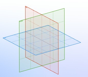
You have just created a new document that already has three standard workplanes – Front, Right and Bottom. You can see that the 3D window with these elements opens automatically within the system window.
For convenience of modeling in 3D window, spinning, panning and zooming of the scene view are available at all times, even when commands are active. Note: the view manipulations while in certain commands require a specific option to be set. These commands will be described below.
To spin the scene press and hold ![]() and move the cursor as desired. One can also use the two arrow key pairs and the pair <Page Up> and <Page Down> for spinning around the three respective axes.
and move the cursor as desired. One can also use the two arrow key pairs and the pair <Page Up> and <Page Down> for spinning around the three respective axes.
Zooming can be done at any moment by scrolling the mouse wheel button (as in IntelliMouse design) or via the provided commands on the "View" toolbar located along the right border of the window. Panning and zooming of the view can also be controlled via <Ctrl>+![]() and <Shift>+
and <Shift>+![]() combinations respectively.
combinations respectively.
As we move the cursor close to a workplane, the latter gets highlighted. T-FLEX CAD provides pre-highlighting on cursor over for all elements in the 3D window depending on the selection filter settings. The selection filter icons are located on the system toolbar.
![]()
To pick an element among the icons, simply press ![]() .
.
Let's select the "Right" workplane. One can see now that 2D drawing commands become accessible. We will further use these commands for creating auxiliary elements in the 3D window.
What auxiliary elements do we need? The first body to be created is a body of revolution. To create it, we will need the contour and the axis of rotation for this contour.
Drawing in 3D window can be performed using any of the tools available for 2D drawing. Thus, one can use the sketching environment for rapid creation of non-parametric models. Accordingly, parametric modeling approach requires creation of construction lines first, then application of graphic lines. The system automatically creates 3D profiles based on drawn graphic lines, to be later used in 3D operations.
To start drawing, call the command,
Icon |
Ribbon |
|---|---|
|
Draw → Construct → Line |
Keyboard |
Textual Menu |
<L> |
Construct > Line |
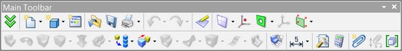
After activating the workplane by any 2D drawing command, the main toolbar is switched to the mode “Workplane”. In this mode a set of icons for working on the active workplane is displayed on the toolbar.
For convenience, the active workplane is reoriented parallel to the screen. However, it can be spun in any desired way, after setting the option ![]() .
.
It is also possible to open the 2D window and continue drawing in 2D mode. Once the 2D window is closed, all changes will be reflected on the 3D scene. The 2D window can be opened or closed using the ![]() icon.
icon.
Let's construct two base lines, a vertical and a horizontal one. To do so, push the following button in the automenu,
![]() <Х> Create two crossing Lines and Node
<Х> Create two crossing Lines and Node
Point cursor at the center of the workplane and click ![]() .
.
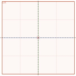
Thus, we have created two orthogonal lines and a node. These will be used as a reference for all further construction.
Press ![]() to quit the last active command. We are now in the parallel line creation mode. (This mode is set by default in the Line command).
to quit the last active command. We are now in the parallel line creation mode. (This mode is set by default in the Line command).
Just like in 2D drawing, we first need to create a framework of thin lines, and then apply graphic lines along the intended segments.
To construct a parallel line, select a reference line first, that will be used as the "parallel" reference for the new one. Similarly to 2D operation, the 3D drawing mode also supports object snapping. Thus, to select a line, move the cursor to the vertical line. The cursor will gain a glyph like this, ![]() . Click
. Click ![]() and move the cursor leftwards. One can see the cursor changing appearance again – it is now rubberbanding a line parallel to the selected.
and move the cursor leftwards. One can see the cursor changing appearance again – it is now rubberbanding a line parallel to the selected.
To fix the line at an arbitrary location, just click ![]() . However, we would like to specify the distance of 100 mm, by typing it in the property window. (In future, this parameter value can be changed at any time as desired.) Press <Enter> to complete the line creation.
. However, we would like to specify the distance of 100 mm, by typing it in the property window. (In future, this parameter value can be changed at any time as desired.) Press <Enter> to complete the line creation.
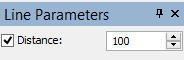
We have just created a line parallel to the selected, at the distance of 100 mm from it. As one can see, rubberbanding resumes at this point. The system is still in the mode of parallel line creation with respect to the original selection. Type a new value of 20 mm right away, followed by <Enter>, thus creating another line. That's all with the parallel line creation for now.
Click ![]() or <Esc> key for quitting the parallel line creation mode.
or <Esc> key for quitting the parallel line creation mode.
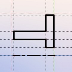
Next, create four more lines in the similar way, parallel to the horizontal base line. Use the distances equal to 20, 40, 60 and 100 mm respectively. The result should look like shown on the following diagram.
Now, apply graphic lines along the construction lines appropriately.
Call the graphic line creation command,
Icon |
Ribbon |
|---|---|
|
Draw → Draw → Graphic Line |
Keyboard |
Textual Menu |
<G> |
Draw > Graphic Line |
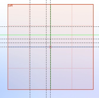
Graphic lines snap to the construction entities – lines, circles, nodes, etc., as well as to construction line intersections. In the latter case, a 2D node is automatically created at intersections snapped to by graphic lines. Straight graphic line segments maintain snapping at their end points. To have an end of a graphic line snapped to some entity, move the cursor to the intended location. Let the cursor snap as indicated by an appropriate glyph, and click ![]() . In this example, we use snapping to construction line intersections and to 2D nodes. Draw the profile as shown on the following diagram. To do so, click with
. In this example, we use snapping to construction line intersections and to 2D nodes. Draw the profile as shown on the following diagram. To do so, click with ![]() at the appropriate points in the order marked on the diagram.
at the appropriate points in the order marked on the diagram.
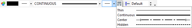
To quit continuous line creation mode, click ![]() . Note that the graphic line creation command is still active. Change the line type in order to draw the axis. To do so, pick the icon
. Note that the graphic line creation command is still active. Change the line type in order to draw the axis. To do so, pick the icon ![]() on the system toolbar and select CENTER type from the pull-down list.
on the system toolbar and select CENTER type from the pull-down list.
Draw the centerline as shown on the following diagram.
Creating rotation operation
One need not quit drawing explicitly in order to create a body of revolution. Simply call the "Rotation" command as follows,
Icon |
Ribbon |
|---|---|
|
3D Model → Create → Rotation |
Keyboard |
Textual Menu |
<3RO> |
Operation > Rotation |
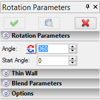
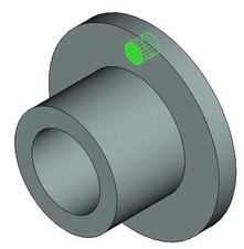
The system automatically determines the rotation axis and the contour among the created lines to be used as a 3D profile. You can preview the result as a wireframe model. In our case, the rotation angle is 360 degrees. Note that the value of 360 degrees for the rotation angle is set by default in the property window. Just confirm the operation by pushing the check button ![]() , and the body of revolution is created.
, and the body of revolution is created.
Creating holes
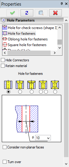
Next, we need to cut six holes in the part. Holes can be created by different methods. The fastest and simplest one is using the dedicated "Hole" operation. The latter allows creating holes of standard shapes in solids, using templates provided in the T-FLEX CAD utility library. In this way, the user only needs to specify the position of the would-be hole within the solid and specify its type and dimensions.
Non-standard holes and slots can also be created without using the dedicated operation. To do this, the user should create an additional solid representing the internal volume of the hole, and then "subtract" it from the main body's volume by a Boolean operation.
Let us consider both techniques.
Creating holes using a dedicated command
First of all, we will create 3D nodes corresponding to the centers of the would-be holes, on one of the part's faces. To create them, we will again use the 2D drawing mode for creating auxiliary 2D nodes on the respective face of the part.
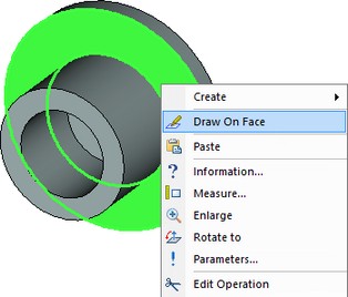
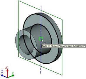
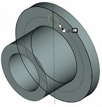
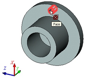
To select a face, move the cursor to the desired element of the model so that it pre-highlights. At this point, press ![]() to invoke the context menu and select "Draw On Face" item in it (see the diagram).
to invoke the context menu and select "Draw On Face" item in it (see the diagram).
If the desired element is not getting pre-highlighted, make sure the selector is set up for this element type. To change selector's settings, you can use selector filter icons on the system panel or select a combination of types from the list.
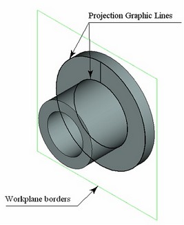
The "Draw On Face" command creates a new workplane based on the selected flat face. The selected face is automatically projected on this plane, and the mode of drawing in the 3D window activates. Further construction can use snapping to elements of the face projection.
Call the command "L: Construct Line" again. Select the following option in the automenu,
![]() <V> Create vertical Line
<V> Create vertical Line
Move the pointer to the center of the circle - the circle center will be pre-highlighted. It is available for snapping to the vertical line. Click ![]() . The constructed line will be snapped to the 2D node which was automatically created at the circle's center.
. The constructed line will be snapped to the 2D node which was automatically created at the circle's center.
Call the command
Icon |
Ribbon |
|---|---|
|
Draw → Construct → Circle |
Keyboard |
Textual Menu |
<C> |
Construct > Circle |
Point the cursor at the center node to select it as the center of the new circle. Specify the radius of the circle equal to 80 mm by typing in the property window. Create a 2D node at the intersection of the vertical line and the new circle using the command:
Icon |
Ribbon |
|---|---|
|
Draw → Construct → Node |
Keyboard |
Textual Menu |
<N> |
Construct > Node |
Now, one can construct a 3D node based on the created 2D node. To do this, without leaving the drawing on face mode, call the command:
Icon |
Ribbon |
|---|---|
|
Draw → Construct → 3D Node |
Keyboard |
Textual Menu |
<3N> |
Construct > 3D Node |
When the 3D node creation command starts, move the pointer to the created 2D node and click ![]() . The 2D node will be highlighted, and the option
. The 2D node will be highlighted, and the option ![]() will become accessible in the automenu. Click
will become accessible in the automenu. Click ![]() , and the 3D node will be created. It will be located in the plane of the selected face, while the 2D node will be its projection on that face.
, and the 3D node will be created. It will be located in the plane of the selected face, while the 2D node will be its projection on that face.
The created 3D node will define the center of one of the six holes. There are two ways to define centers of other holes:
1. Construct five more 2D nodes on the same workplane and create the required 3D nodes based on the 2D ones (similar to the first 3D node creation);
2. Create the required 3D nodes by means of a 3D array based on the first 3D node.
The second method is faster, so we will use it in this case. Call the command "3AR: Create Circular Array":
Icon |
Ribbon |
|---|---|
|
3D Model → Create → Circular array |
Keyboard |
Textual Menu |
<3AR> |
Operation > Circular array |
You do not have to explicitly finish the draw on face moden - it will terminate automatically upon launching the 3D array creation command.
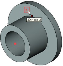
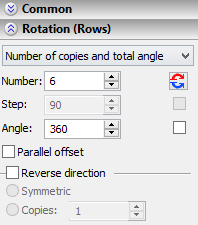
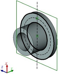
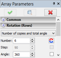
In the command's properties window, set the array type as "Array of Construction". Then, in the 3D window, move the pointer to the created 3D node (the latter shall highlight) and click ![]() to select it. If all was done right, the name of the 3D node selected for copying shall appear in the properties window. After that, you need to specify the rotation axis of this circular array. To do this, you can use a pair of 3D nodes automatically created when defining the axis for the rotation operation. Select these two 3D nodes one by one. Next, let's specify what array parameters will be used ("Number of copies and total angle"), in the "Rotation (Rows)" section of the properties window, and enter the required values of the parameters (the number of copies – 6, the total angle – 3600). To complete creation of this circular array of 3D nodes, simply click
to select it. If all was done right, the name of the 3D node selected for copying shall appear in the properties window. After that, you need to specify the rotation axis of this circular array. To do this, you can use a pair of 3D nodes automatically created when defining the axis for the rotation operation. Select these two 3D nodes one by one. Next, let's specify what array parameters will be used ("Number of copies and total angle"), in the "Rotation (Rows)" section of the properties window, and enter the required values of the parameters (the number of copies – 6, the total angle – 3600). To complete creation of this circular array of 3D nodes, simply click ![]() .
.
|
|
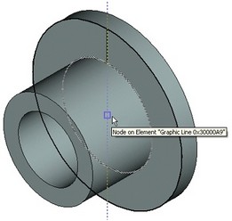
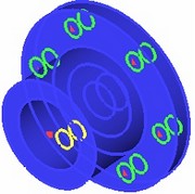
Selecting 3D node to copy |
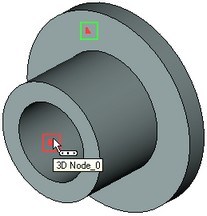
Selecting first 3D node of the array's axis of rotation |
|
|
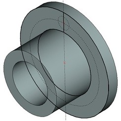
Selecting second 3D node of the array's axis of rotation |
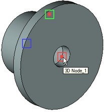
Result of creating an array of 3D nodes |
After creating the array of 3D nodes, you can call the command "3H: Create Hole":
Icon |
Ribbon |
|---|---|
|
Draw → Draw → Hatch |
Keyboard |
Textual Menu |
<H> |
Construct > Hatch |
Upon entering the command, you need to activate the option:
After that, move the pointer to one of the 3D nodes of the circular array and click At the bottom of the properties window there is a pane with a schematic image of the hole of the selected type and fields for entering the hole parameters. Set the hole diameter to be 20 mm. The following option will be automatically activated in the command's automenu for the holes of this type:
When this option is set, the depth of the holes will be defined automatically by the part's thickness. To complete creation of holes, simply click |
|
Creating holes without using a special command
In this approach, initial constructions of the holes creation will be same as in the previous method.
You select a part's face and call the context menu command «Draw On Face». Call the command "L: Construct Line". Select the automenu option ![]() . Construct a vertical line passing through the center of the circle (of the face's projection). Then, call the command "C: Construct Circle". Create the circle with the radius equal to 80 and the center at the central node. Similarly, create another circle with the radius equal to 10 mm at the intersection of the previous circle's circumferential and the vertical line.
. Construct a vertical line passing through the center of the circle (of the face's projection). Then, call the command "C: Construct Circle". Create the circle with the radius equal to 80 and the center at the central node. Similarly, create another circle with the radius equal to 10 mm at the intersection of the previous circle's circumferential and the vertical line.
Then draw graphic line over the newly created circle. To do so, call the graphic line creation command,
Icon |
Ribbon |
|---|---|
|
Draw → Draw → Graphic Line |
Keyboard |
Textual Menu |
<G> |
Draw > Graphic Line |
Pick the ![]() icon on the system toolbar, and select CONTINUOUS type from the pull-down list.
icon on the system toolbar, and select CONTINUOUS type from the pull-down list.
Move the cursor to the just drawn circle. The circle will get highlighted, and the cursor gain a circle glyph. Once so, click ![]() , that applies graphics over the whole circle. On a crowded drawing with multiple elements near the cursor, snapping may occur to an unintended element. In such cases, the circle can be explicitly selected by typing <C> key. This will select the circle nearest to the cursor.
, that applies graphics over the whole circle. On a crowded drawing with multiple elements near the cursor, snapping may occur to an unintended element. In such cases, the circle can be explicitly selected by typing <C> key. This will select the circle nearest to the cursor.
Two possible approaches are available for further construction. One could draw five more circles, to extrude and subtract them all from the body of the part. Alternatively, extrude just a single circle, and then "replicate" the resulting hole by means of the circular 3D array.
The first approach by steps:
A handy tool for creating the required number of copies of the circle is the "Create Circular Array" command:
Icon |
Ribbon |
|---|---|
|
Draw → Additional → Circular array |
Keyboard |
Textual Menu |
<XR> |
Operation > Array > Circular |
Once in the command, the system waits for selection of a graphic entity. Move the cursor to the image of the hole and click ![]() to select the graphic line. That's all to be selected, therefore, press
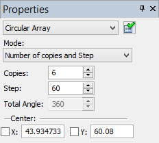
to select the graphic line. That's all to be selected, therefore, press ![]() in the automenu. Now the system expects selection of the array center, which must be a 2D node. Note that the default setting for the number of copies of the circular array is 4, and we need six. Therefore, specify the correct parameters in the property window, as shown on the diagram at right. Now you can select the node. Move the cursor to the center node and click
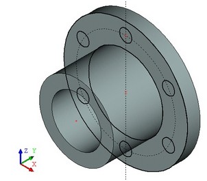
in the automenu. Now the system expects selection of the array center, which must be a 2D node. Note that the default setting for the number of copies of the circular array is 4, and we need six. Therefore, specify the correct parameters in the property window, as shown on the diagram at right. Now you can select the node. Move the cursor to the center node and click ![]() . The result will look as on the following diagram.
. The result will look as on the following diagram.
Next, we will need to call the profile extruding command,
Icon |
Ribbon |
|---|---|
|
3D Model → Create → Extrusion |
Keyboard |
Textual Menu |
<3X > |
Operation > Extrusion |
The system automatically makes a 3D profile from the drawn lines and sets the extrusion vector normal to the profile.
The amount of extruding, that is, the depth of the hole, can be defined in various ways (by a numerical value, by the length of the direction vector, etc.). In this particular case, we need to get a through hole, that is the one penetrating the entire width of the part. In the properties window, set the "First direction" parameter to the value "Through all", by selecting from the drop-down list. In this definition, the extrusion amount is determined by the thickness of the auxiliary bounding body. Additionally, the created extrusion is automatically subtracted from that body. This method of specifying the extrusion distance was devised specifically for quick creation of through holes in various bodies.

The option of creating a Boolean operation will automatically activate in the automenu:
![]() <Ctrl><B> Subtraction
<Ctrl><B> Subtraction
Since only one body is present in the scene at the time of creating the extrusion, it will be automatically selected as the bounding body and the first operand of the Boolean subtraction.
Upon clicking ![]() , two operations will be created at once – an extrusion and a Boolean operation.
, two operations will be created at once – an extrusion and a Boolean operation.
The second approach by steps:
Call the profile extruding command,
Icon |
Ribbon |
|---|---|
|
3D Model → Create → Extrusion |
Keyboard |
Textual Menu |
<3X > |
Operation > Extrusion |
Specify extrusion length parameter equal to 20 in the reverse direction, and confirm the extrusion operation.
Next, let's call the circular array creation command,
Icon |
Ribbon |
|---|---|
|
3D Model → Create → Circular array |
Keyboard |
Textual Menu |
<3AR> |
Operation > Circular array |
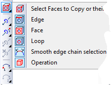
In the command's properties window, select the array type – "Array of Faces".
The following option will be automatically activated in the automenu:
![]() <N> Select Faces to Copy or their boundary Edges or Loops
<N> Select Faces to Copy or their boundary Edges or Loops
Aim the pointer at the cylindrical face of the hole and click ![]() .
.

If edges or loops highlight instead of the face, then you can do any of the following: - rest the pointer over the face until the multiple selection widget - before selecting the face, set up the list of 3D objects available for selection (banning from selection anything but faces). To do this, double-click Once the intended operation is selected, the system expects input of the axis of revolution for the array. The axis can be assign by the same two 3D nodes as those used in the first method of creating holes. Select these two 3D nodes one by one. You can define the array parameters in the properties window – number of copies and total angle. |
|
Press the ![]() button in the automenu to complete the operation. As a result, five new faces will be "embedded" in the original body, making up the additional holes.
button in the automenu to complete the operation. As a result, five new faces will be "embedded" in the original body, making up the additional holes.
Creating a blend
The next step is finalizing 3D model creation. This includes creation of a chamfer and a rounding.
Call the command
Icon |
Ribbon |
|---|---|
|
Draw → Construct → 3D Node |
Keyboard |
Textual Menu |
<3N> |
Construct > 3D Node |
Pick the following option in the automenu,
![]() <E> Select Edge
<E> Select Edge
The system is waiting for an edge selection. Select two edges in the order shown on the following diagram.
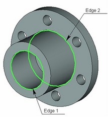
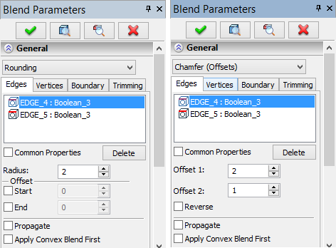
Next, specify the operation parameters. Each edge can be assigned its specific set of parameters in the property window by unchecking the "Common Properties" option. Select the first edge in the list and specify the blending type as Rounding with Radius equal to 2 mm. For the second edge, define the blending type as Chamfer (Offsets), with Offset1 and Offset2 both equal to 5 mm. Confirm the operation by pressing ![]() . The result appears as shown on the following diagram.
. The result appears as shown on the following diagram.
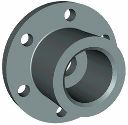
This completes creation of the given 3D model.
Creating a drawing
Open a 2D window. Do this as follows. Move the cursor to the bottom-left corner of the 3D window and locate the split box before the scroll bar. As the cursor approaches the split box, it changes to juxtaposed arrows. Press ![]() and dialog box “Views Placement” will appear. Choose
and dialog box “Views Placement” will appear. Choose ![]() and press [OK].
and press [OK].
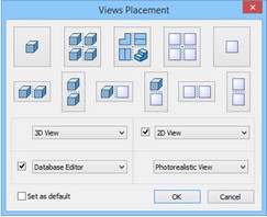
The 2D and 3D windows will be located side by side of the vertical split bar. The same result could be obtained by calling the command
Icon |
Ribbon |
|---|---|
|
View → Window → Split Vertically |
Keyboard |
Textual Menu |
<WSR> |
Window > Split Vertically |
A new window can also be opened with the command
Icon |
Ribbon |
|---|---|
|
View → Window → New Window |
Keyboard |
Textual Menu |
<WO> |
Window > New Window |
To activate the newly opened 2D window, place the cursor within and click ![]() .
.
Now we can generate projections and sections. Call the projection creation command,
Icon |
Ribbon |
|---|---|
|
Draw → 2D Projection |
Keyboard |
Textual Menu |
<3J > |
Draw >2D Projection |
Press the automenu button
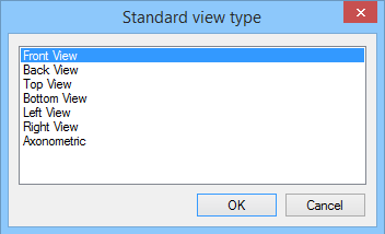
![]() <6> Create standard projection
<6> Create standard projection
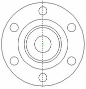
In the coming dialog box, select "Back View" and press [ОК].
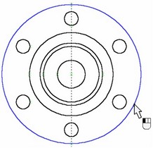
A green box will be displayed on screen, marking the size of the projection to be created. Next, use the option
![]() <T> Change Projection Placement
<T> Change Projection Placement
Define the attachment point of the projection in absolute coordinates by clicking ![]() at the desired location in the 2D window. Press
at the desired location in the 2D window. Press ![]() in the automenu to confirm projection creation.
in the automenu to confirm projection creation.
Next, let's generate a section of the part.
First, we need to do some auxiliary construction. Call the line creation command,
Icon |
Ribbon |
|---|---|
|
Draw → Construct → Line |
Keyboard |
Textual Menu |
<L> |
Construct > Line |
Pick the automenu option for creating vertical lines,
![]() <V> Create vertical Line
<V> Create vertical Line
Point at the center of the circle and click ![]() , creating a line along the symmetry axis of the projection.
, creating a line along the symmetry axis of the projection.
Then, call the circle creation command,
Icon |
Ribbon |
|---|---|
|
Draw → Construct → Circle |
Keyboard |
Textual Menu |
<C> |
Construct > Circle |
Next, we need to reconstruct a construction circle from a graphic circle on the projection.
Move the cursor to the circle graphic line and click ![]() .
.
Now, we can create the section points snapped to construction line intersections. Call the section creation command,
Icon |
Ribbon |
|---|---|
|
Draw → Title Block → Section |
Keyboard |
Textual Menu |
<SE> |
Draw > Section |
Select two intersection points between the line and the circle one by one. Press ![]() automenu icon to confirm the section creation.
automenu icon to confirm the section creation.
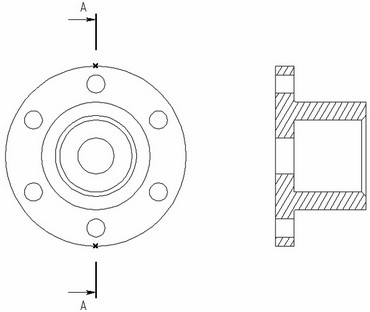
The next step will be creating a projection of the newly created 2D section. Call the 2D projection creation command,
Icon |
Ribbon |
|---|---|
|
Draw → 2D Projection |
Keyboard |
Textual Menu |
<3J > |
Draw >2D Projection |
In the automenu, select subsequently the following options,
![]() <2> Create section view
<2> Create section view
![]() <L> Select Section defining Projection
<L> Select Section defining Projection
Point the cursor at the section symbol and click ![]() . The outline of the section appears rubberbanding with the cursor. The projection outline will slide along the projection direction adjusting to the cursor movement. To fix the placement, click
. The outline of the section appears rubberbanding with the cursor. The projection outline will slide along the projection direction adjusting to the cursor movement. To fix the placement, click ![]() .
.
To complete projection creation, press ![]() in the automenu.
in the automenu.
If necessary, the projection entities (graphic lines, arcs and circles) can be used as references for dimensions, auxiliary graphic lines such as centerlines, and drawing layout attributes.