Rotation |
  
|
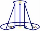
Rotation |
|
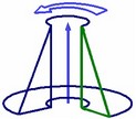
Rotation operation creates solids by rotational sweeping of the shape-defining element – the rotation contour about an axis in space. The surface of the profile can be arbitrarily positioned with respect to the axis, but is not allowed to intersect the axis. Flat contours may not be orthogonal to the axis of revolution.
The rotation contour can be made of wire or sheet geometry objects. The resulting rotation is a sheet or solid body, depending on the type of the contour geometry.
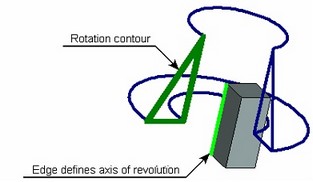
The axis of revolution can be defined by any suitable 3D elements: 3D nodes, edge, axis of a surface of revolution, coordinate axis, etc.
Main concepts. Operation capabilities
Rotation operation has much in common with the extrusion operation, since both operations belong in kinematical operation group. Both operations have the same rules of selecting the original contour, create bodies of the same types and share the same additional functionalities. Therefore, in this chapter we won't be concerned with the rotation operation capabilities that are common to both operations and were already described in the "Extrusion" chapter.
Rotation contour
The rotation contour can be composed of one or several wire or sheet objects. If selecting several objects, only same-type objects are allowed, either all wire or all sheet objects.
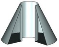
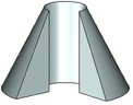
The result of rotation of a wire contour is a sheet body. Extrusion of a sheet contour makes a solid body.

Axis of revolution
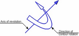
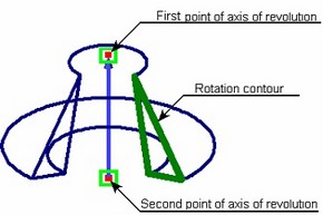
The axis is represented by the vector. The specified contour is rotated about this axis. The direction of contour rotation is defined by the right-hand screw rule: rotation is counter clock-wise as watched in the arrow direction. The axis can be defined either by a pair of 3D points for the axis to pass through or by selecting some 3D model element, suitable for defining a line.
If a 3D node was selected as the first point that was based on a 2D node, then only one point is enough. In this case, the direction is defined by the normal to the workplane hosting the 2D node.
The axis can be defined explicitly by following 3D objects: flat curved edges that are arcs (in this case the axis of the arc edge is used as the axis of revolution), straight edges (the axis coincides with the edge), coordinate systems (one of the axes is used), surfaces/faces that are part of a cylinder or torus (the axis of the surface/face is used as the axis of revolution), various curves (the axis is defined by the normal or binormal to the curve at the specified point). The direction of the axis is defined by the direction of the selected element.
Angle of contour rotation
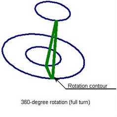
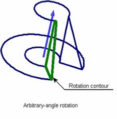
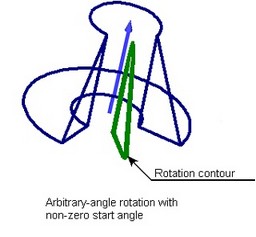
Rotation is performed from the original contour position by the angle specified by the user, no greater than 360 degrees (full turn). Additionally, the start angle of rotation can be specified. In this case, the contour will be rotated about the axis starting from the position defined by the start angle of rotation, for the amount of the specified rotation angle.
The start angle and the rotation angle are defined either by numerical values in the operation parameters dialog or by specifying additional 3D points.
Add-on features of rotation operation
Additional features of the rotation operation include:
● Filleting of side edges of the resulting body. Besides, for bodies created by rotating by less than 360 degrees, rounds or chamfers can be applied on the end faces;
● Thin-wall body creation mode;
● Using created body in Boolean operation.
Detailed description of these features is provided in the "Extrusion" chapter.
Creating rotation operation
To create a body by rotation operation, use the command "3RO: Create Rotation". The command can be called as follows:
Icon |
Ribbon |
|---|---|
|
3D Model → Create → Rotation |
Keyboard |
Textual Menu |
<3RO> |
Operation > Rotation |
The following steps are to be done to create the operation:
1. Select Rotation contour
2. Specify axis of revolution
3. Define the start angle and rotation angle (optional in some cases)
4. Define add-on feature parameters (optional, performed as described in the "Extrusion" chapter.)
5. Confirm operation creation
Contour and axis of revolution selection can be automatic if calling the command in the active workplane drawing mode. In this case, the system will automatically create a 3D profile based on the continuous graphic lines or a hatch and select it as the rotation contour. If only a single dash-dotted line was created on the workplane, it will be automatically selected as the axis of revolution.
Rotation contour selection
To create the operation, first define the rotation contour. Upon calling the command, the following option activates automatically in the automenu:
![]() <R> Select Contour
<R> Select Contour
To select a contour for the rotation, move the cursor over the desired element in the 3D window. The pointed at element will be pre-highlighted, and the cursor gain a tooltip with its name. Click ![]() for selection.
for selection.
3D profiles based on hatches can be selected by picking the original hatch in the 2D window.
After selecting the rotation contour, the option will appear in the automenu for rejecting the contour:
![]() <H> Cancel contour selection
<H> Cancel contour selection
Defining axis of revolution
After selecting the rotation contour, define the axis of revolution.
To define the axis by an arbitrary 3D model element, use the automenu option
![]() <A> Select axis of revolution
<A> Select axis of revolution
This option allows selecting a 3D element, suitable for defining the axis of revolution. The pull-down list of this option contains appropriate filters for selecting various objects. Pay attention to the active filters when selecting elements.
To define axis of revolution by two 3D points, use the following automenu options (activate sequentially):
![]() <F> Select 1st Point of axis
<F> Select 1st Point of axis
![]() <S> Select 2nd Point of axis
<S> Select 2nd Point of axis
A 3D point can be defined by selecting a 3D node, a vertex of a body, profile or path. Besides, an edge can be picked – in this case, the 3D point will be defined by the edge midpoint (for straight edges) or center (for edges that are arcs, circles and ellipses). Selecting a face, which is part of a sphere or torus, yields the point at the sphere/torus center. A coordinate system selection yields its origin as the 3D point. The set of elements allowed for selection is defined by the state of selection filters in the pull-down lists of the described options.
The axis can be defined by a single point by selecting as the first point a 3D node based on a 2D node. In this case, the axis is defined by the normal to the workplane hosting the 2D node.
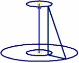
Upon defining the axis, a wireframe preview of the resulting rotation is displayed in the 3D window, with an arrow showing the position and direction of the axis of revolution.
Defining start angle and rotation angle
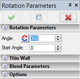
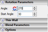
The start angle and rotation angle are defined in the command property window in the section "Rotation Parameters". By default, the system offers a 360-degree rotation (full turn of the contour) and zero start angle (the contour will be rotated from its original position). If necessary, the default parameters can be modified. The rotation angle is defined by the parameter "Angle". To change the start angle of the rotation, enter the desired value in the "Start Angle" input box.
The wireframe preview on the 3D scene shows the resulting rotation with the current parameters. Both the start angle and rotation angle can be defined directly on the 3D scene. As the cursor approaches the preview of the body being created, it gains a mark ![]() (for the start angle) or
(for the start angle) or ![]() (for the rotation angle). Dragging the cursor with
(for the rotation angle). Dragging the cursor with ![]() depressed dynamically sets the value of either angle. The numerical value of the angle is displayed in the property window.
depressed dynamically sets the value of either angle. The numerical value of the angle is displayed in the property window.
Rotation parameters can be defined by additional 3D points selected with the help of the following automenu options:
![]() <1> Select starting point of Rotation
<1> Select starting point of Rotation
![]() <2> Select ending point of Rotation
<2> Select ending point of Rotation
These options become sequentially accessible after defining the axis of revolution. Both options contain pull-down lists with filters for selecting elements suitable for defining a 3D point.
When using 3D points, consider the type of the rotation contour. If the contour is flat then the specified points define the start and end positions of the contour plane in the rotation (the contour plane will be passing through the specified points in these positions). Therefore, the first point defines the start angle, and the combination of the two – the rotation angle. One can only specify the first point, and then enter the rotation angle numerically in the parameters dialog box.
When using 3D points for a non-flat contour, always define both points. Note that in such case, the point positions define the rotation angle only, as the start angle is always set to zero (the rotation starts at the original contour).
After defining the 3D points, dynamic angle modifications are no longer available on the 3D scene. The respective parameter input boxes also become inaccessible in the command property window.
Selection of 3D points can be cancelled by the automenu option
![]() <K> Cancel selection of points for Rotation
<K> Cancel selection of points for Rotation
Using the created rotation in a Boolean
To create a Boolean operation, do the following:
1. Turn on the Boolean creation mode by the automenu option
![]() <Ctrl+B> Select original body for Boolean operation
<Ctrl+B> Select original body for Boolean operation
A Boolean is created when the icon is pushed.
2. Select the type of the operation from the pull-down list under the above option:
![]() <Ctrl+'+'> Addition
<Ctrl+'+'> Addition
![]() <Ctrl+'-'> Subtraction
<Ctrl+'-'> Subtraction
![]() <Ctrl+'*'> Intersection
<Ctrl+'*'> Intersection
![]() <Ctrl+l> Smart mode
<Ctrl+l> Smart mode
Operating principles of the Smart mode:
●If the body being created and the existed selected body have intersection of volumes - the type of Boolean operations: subtraction.
●If the body being created lies entirely within the selected body - the type of Boolean operations: subtraction.
●If the body being created touches and selected body touch each other - the type of Boolean operations: addition.
●If conditions set out above are not met, or a selected body lies inside the created, or error occurred determining the type of penetration, then, Boolean type is not defined - the Boolean operation will not be created.
3. Select the target body for the Boolean (optional in some cases), using the automenu option
![]() <Ctrl+T> Select Target Body for Boolean
<Ctrl+T> Select Target Body for Boolean
If only one body exists in the scene, it is selected automatically. The new body created by the extrusion operation becomes the tool body of the Boolean.
Upon confirming operation creation, first the body is created by the rotation operation, and then the specified type Boolean is performed.