Blend |
  
|
Blend |
|
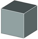
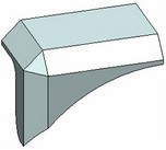
The edge blending operation makes transition between two or more adjoining surfaces belonging to one solid body. Blending can be performed on both solid and sheet bodies.
There are several types of blend:
- chamfer (offset; length-angle);
- rounding;
- variable-radius rounding (circular, elliptical).
As the result of the operation, the edge where two faces meet is replaced by an additional surface (the blend surface) providing the required transition from one face to the other.
In the edge blending operation there is a special diagnostics mode available which allows a user to promptly estimate possibility and causes of error appearance.
Main concepts. Operation capabilities
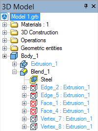
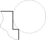
The object of the edge blending operation is the edges of the sheet or solid body. Additionally, some vertices may be selected on the involved edges in order to specify particulars of the intended shape. The set of the automenu options allows selection of various objects, besides the edges, such as loops, faces, vertices and operations. This helps selecting certain common combinations of edges. Thus, for instance, by selecting a vertex, we select all the edges meeting at that vertex. Selecting a loop by the definition means selection of the sequence of edges making this loop. Selecting a face results in selection of all its surrounding edges (single or multiple loops). Selecting a solid automatically makes selected all its edges appropriate for blending.
It is very important to understand how the information is maintained about the original elements subjected to blending. These original elements selected for blending are remembered in the model history. Thus, in case a face was selected, a reference to this face is recorded in the model tree. In this case, the set of edges to blend is built anew at each regeneration. This way of selecting brings the advantage of having a quite robust operation. If topology of the selected object changes (for example, the number of edges changes), the operation will be correctly regenerated with the new set of edges of the involved object. Otherwise, if a specific edge were selected that would later disappear, then the system would output an error. |
|
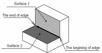
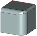
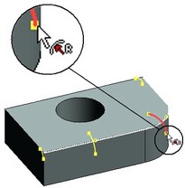
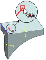
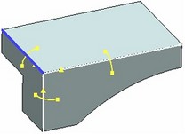
Each selected edge has a direction indicated by an arrow. Other blend-defining conditions depend on this direction. The arrow tail defines the edge start. According to an agreement, the surface on the right-hand side of the edge, as looked in the arrow direction, is conventionally called the first blend surface, and the one on the left-hand side – the second. |
|
Types of blend
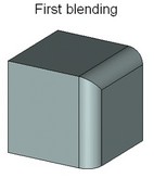
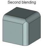
Rounding
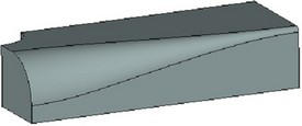
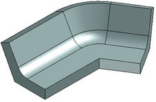
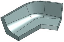
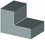
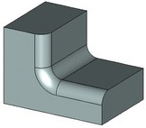
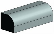
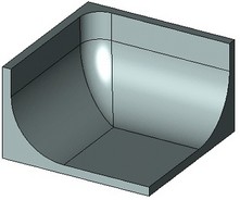
Rounding is a most commonly used type of blending. A surface is created along the selected edge, providing a smooth transition from one face to the other. A condition holds that any normal cross section of this surface with respect to the edge is an arc of the specified radius.
To easily realize how the rounding surface is generated, imagine a ball of the specified radius rolling along the selected edge, touching the faces adjacent to the edge. The trace of the ball represents the blend surface for the given edge. The surface may be defined in a single or multiple passes, particularly, if different edges are rounded with different radii. Complex spline surfaces may be constructed to join multiple edge blends.
The operation may add or remove material, depending on whether the angle between the faces of the blending edge is convex or concave.
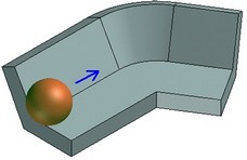
The rolling ball must be touching at least one of the adjacent faces. Otherwise, rounding will fail and the system will output an error.
Variable-radius rounding
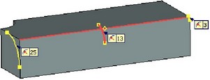
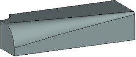
This type of rounding creates a surface of a variable radius. A list of critical points is defined. A certain value of the rounding radius can be set at each of these points. Each point position is defined as percentage of the total edge length. Initially, this list contains two points at 0% and 100% of the edge length.
If several edges are selected, then the point positions are defined as percentage of the total chain length for all consequently adjoined edges. The edge joints are not required to be smooth. A single direction is used for the whole chain of edges. It is defined by the direction of the first edge in the chain.
When defining this type of blending along a closed loop of edges, always make sure that the start and end point radii are equal.
The change in the rounding radius between points can be linear or smooth. In the linear case, the change in the radius is described with a broken line (the radius changes linearly from one point to another). In the smooth case – the change in the radius is specified by a curve having a horizontal tangent at the start and end points.
|
|
|
|
Linear change of radius |
Smooth change of radius |
A special mode is provided for processing certain cases, that allows specifying own variable rounding parameters for each individual edge. When processing a smooth chain of edges in this mode, make sure the radii are equal at the meeting ends of the adjacent edges.
Variable-radius elliptical rounding
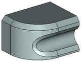
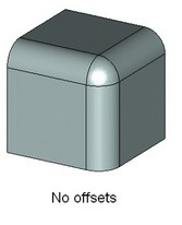
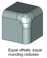
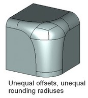
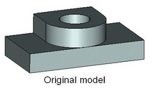
This type of rounding allows creation of advanced blend surfaces. The sizes and shape of the blend surface is defined by the offsets from the first and the second faces (as conventionally denoted), and by the rho (convexity) value.
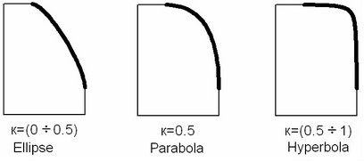
Depending on the rho value of the surface cross section, all resulting surfaces are divided in three groups:
· The first group is with a rho value between 0 and 0.5, excluding the bounds. This results in elliptical shape of the surface cross section.
· The second group is limited to the surfaces with a rho value of 0.5. This rho value corresponds to the parabolic shape of the blend surface cross section.
· The third group lies in the range from 0.5 to 1 (exclusive). In this case, the blend surface has hyperbolic shape.
The shape of the surface can be defined at any point on the edge or on the chain of edges. The list is managed in the same way as in the case of the circular variable-radius rounding. The change in the rounding radius between points can be also linear or smooth as in the circular variable-radius rounding.
The offsets from the faces define the boundaries of the blend surface. The algorithm of constructing the blend surface is common for elliptical rounding and offset chamfer. It is illustrated on the following diagrams:
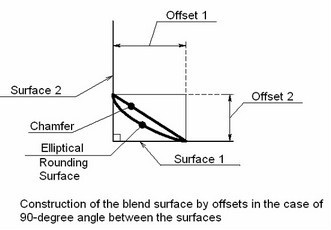
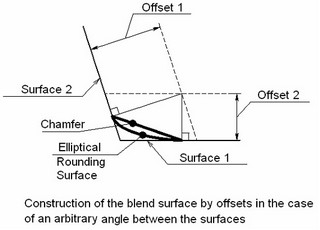
1. An offset surface is constructed at the distance Offset_1 from the second face.
2. Another offset surface is constructed at the distance Offset_2 from the first face.
3. The intersection line between the two offsets is projected on the original faces, thus defining the boundaries of the blend surface.
In the special case of blending two flat orthogonal faces, this means the distance from the blended edge to the side boundary of the blend surface is equal to the value of the offset.
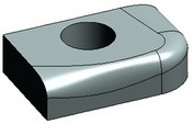
Chamfer
A chamfer can be constructed along a selected set of edges. A chamfer can be defined by two offsets from the adjacent faces or by the slant angle and the radius. The algorithm of constructing a chamfer by an offset and an angle is illustrated on the following diagrams:
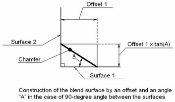
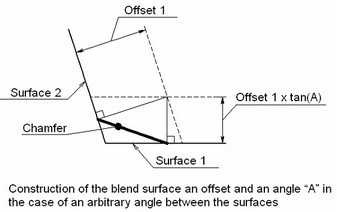
The second offset is computed based on the angle, by multiplying the value of the first offset by the tangent of the angle. Further computations follow the algorithm of constructing a chamfer by two offsets.
When creating a chamfer, the faces are not required to be flat and the edges straight. They can be of various geometrical shapes (see the diagrams below).
Specifics of blending sets of edges
Automatic vertex blending
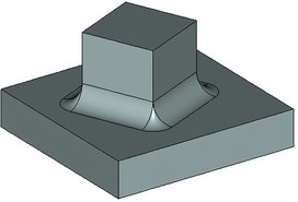
A single operation can be used for rounding all edges meeting at one vertex. The edges can be of either the convex or the concave type. Simultaneous rounding of edges automatically involves rounding of the vertex where the edges meet.
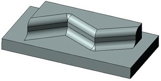
To avoid the vertex blending, do the edge blending by two blending operations, first blending any two edges meeting at a vertex, and then the third edge. The result in this case will look as shown here:
Sometimes it is impossible to blend all edges at once, and the system outputs en error. In this case, try creating the intended blends by steps.
The above implies that proper handling of the operation leads to successful blending of practically any edges of any model.
It is recommended to use as few operations as possible when blending several edges of one solid. Prefer blending a set of edges by one operation, rather than by a number of operations one edge at a time. With this approach, the model regeneration is much faster, and the rounding algorithm most likely performs best.
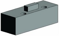
Blending two of three edges meeting at a vertex
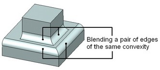
When blending a pair of edges of the same convexity, two blend surfaces are constructed – one per edge. The vertex is not blended in this case; rather, new edges are created at intersections of blend surfaces.
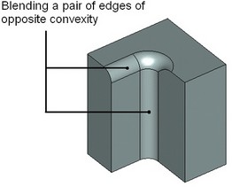
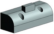
However, when blending a pair of edges of opposite convexity, the vertex where the edges meet is automatically blended.
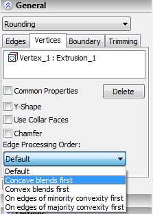
Processing of vertices joining edges of different convexity
Consider the special case when three edges of different convexity meet at a vertex.
Should it have been just two edges of the same convexity, one could use the option of also blending their common vertex. This would require selecting the vertex as well. The results would have looked like on the diagrams below:
Blending a group of edges with an offset from the vertex
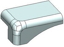
When rounding a group of edges meeting at a vertex, one can specify an offset from this vertex. The following diagrams demonstrate how this offsetting affects the shape of the resulting blend:
One can see that the offset defines a zone of smooth transition from one blend surface into the other. The specified radius of rounding is not guaranteed in the transitional zone.
The "Offset" parameter can be specified at any edge start and end. However, offsetting can be done only for a set of three or more edges meeting at a vertex. Some of the meeting edges may be directed away and some towards the vertex. That said, make sure the offsets are defined on the vertex side for all edges. If an edge connects two vertices, each subject to offsetting, then the offsets are to be defined for both the edge start and end.
In some cases, T-FLEX CAD system allows automatic synchronization of the "Offset" parameters for the edges with opposite direction. This happens, for instance, when selecting a group of edges by picking a vertex. (Detailed description of the steps for defining offsets follows).
Special dynamic draggers are provided for marking offsets on the edges while defining the operation parameters. Their presence and location help easily realize the offset parameters and modify, if necessary, by the mouse.
Special processing of edge blends
Y-shape
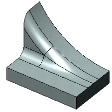
Suppose, two edges of opposite convexity are tangent at a vertex with three or more faces meeting there. In such a case, a special procedure is available for blending the vertex - the so-called Y-shape blending. In this way, surfaces come out lesser curved in the transitional zone around the vertex, then in the conventional way of blending.
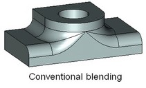
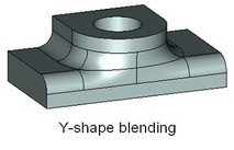
The presented way of processing a vertex is only applicable for creating constant-radius or variable-radius rounds.
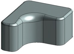
Topology deletion
In the cases when the rounding surface completely embraces other topological entities, two ways are possible of processing the operation. The system can keep all topological entities, trimming or extending all necessary pieces of the surfaces involved. Alternatively, only the blend surface can be left, with all embraced objects deleted.
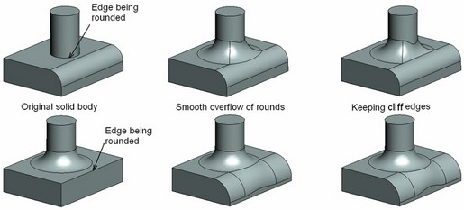
Overflow processing
In real situations, an overflow may quite often occur between the rounding surface and some elements of the solid geometry that are not the adjacent faces of the rounded edge. In such cases, the system may use special options for processing various types of overflow. Four types of overflow are processed:
●Smooth overflow – when the rounding surface smoothly merges into another rounding belonging to the solid body being processed. The surface is deformed in the transition zone in order to provide tangency to both the original face and the surface being merged into.
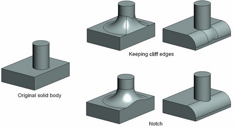
●Keep cliff edges – when the rounding surface "creeps" over an edge not subject to rounding. The rounding surface is constructed near the zone of contact with the edge by the rolling ball method. The surface is swept by a ball rolling on top of the "constraining" edge, touching one of the original faces. When processing an overflow that keeps cliff edges, you can additionally engage or disengage the algorithm for processing the cases when only a portion of the surface being blended (on the sides - cliff end) "creeps" on the cliff edge. Disengaging more complex algorithms that are not required would allow speeding up to some extent the model regeneration.
●Notch – the rounding is constructed in such a way that the element affected by the overflow is ignored. The rounding surface is not deformed in this case, and the surfaces of the notch element are trimmed or extended to the rounding.
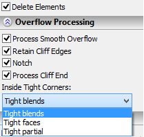
●Inside tight – some portions of the model subjected to blending are represented by the surfaces with so small curvature radius that the blending ball of the specified radius cannot roll through while maintaining contact with the sidewalls. In such a case, the system can use special processing for providing blending with the specified radius in the curved zone:
- Tight blends – in this case, the system will process the curved zones using the fastest algorithm. The algorithm assumes that the surfaces in these zones are created solely by blends of constant radius. If the type of the original surface is different and the new blend cannot be created, an error is output.
- Tight faces – the system processes the curved zones, assuming, that the zone of small curvature radius fully extends through some face of a sidewall.
- Tight partial – this is the most complex, but also versatile, algorithm. It allows processing the cases, when the zone of small curvature radius covers the portion of a sidewall of the blend. In this case, the blend surface is additionally subdivided in order to provide correct processing.
With an option engaged, the system processes the respective type of overflow when occurs. If various types of overflow occur between the rounding being created and several other rounds then the system finds an optimum solution. The order of applying possible solutions in this case will be first the smooth overflow, then the overflow with cliff edges, and, finally, the notch. The type of processing of the curved zones depends on the selected algorithm.
The user can control the system behavior when overflow occurs. The user usually gets involved when the results are different from expected. You can set the overflow options in any desired combination.
The system attempts applying all three types of processing overflow in the presented order. If any of the overflow types is turned off, it is excluded from the list and is not applied.
If all three options are turned off when rounding overflow occurs against the body faces and edges, then the system gives up rounding and outputs a message about a failing rounding.
The following set of examples demonstrates the operation capabilities when using various types of overflow processing:
1. Overflow processing example: switching the smooth overflow option on and off. The "Notch" option is not applicable in this example.
2. Overflow processing example: switching on/off the option "Keep cliff edges". The "Smooth overflow" option is not applicable in this example.
3. Example of constructing a blend surface with the option "Keep cliff edges" turned on. This is the situation when the blend surface of the specified radius cannot be made tangent to both faces of the edge being rounded. If the option is turned off, the system will output a message about a failing rounding.
4. Examples of processing zones of small curvature radius on blend sidewalls based on various algorithms. In the areas where the blend radius is created then the curvature radius of a sidewall of the blend, the system makes a correction of the blend surface.
Unprocessed original "Tight blends" processing
Unprocessed original "Tight faces" processing
Unprocessed original "Tight partial" processing
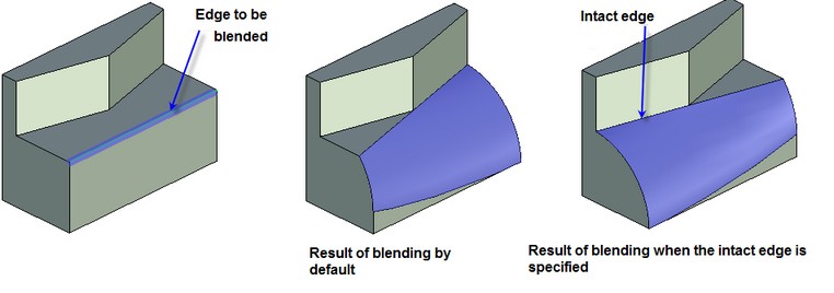
Explicit specification of intact edges
When the blending is created, it is possible to specify the edges of the body which must remain intact upon blending. As a result, the blend surface will contain these edges.
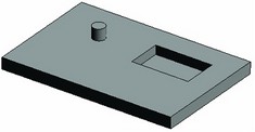
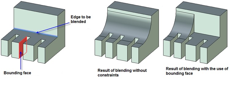
Specifying bounding geometry
Specification of the bounding geometry allows us to bound the blending by the geometry of an arbitrary face, a plane or a list body. This functionality allows us to perform the blending in various complex configurations.
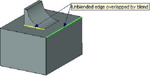
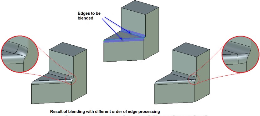
Specifying the order of creation of blending when blend surfaces overlap on several edges
When the blend surfaces overlap on several edges of different convexity, it is possible to achieve the desired behavior of these surfaces by changing the order in which the blending will be performed. The order of the blending is determined by the selected priority of the edge processing: at first concave or at first convex.
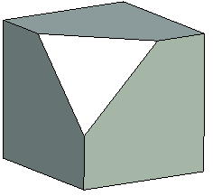
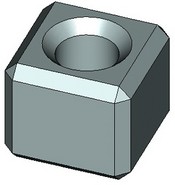
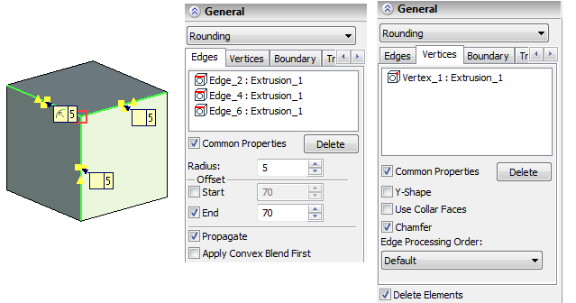
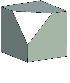
Specifying chamfer at the vertex
For a vertex at which three edges meet it is possible to create a chamfer without specification of the blending on adjacent edges. This option works without specification of radii of the blending; it works simply by selection of the vertex with three edges. It constructs the triangle through the points that are shifted from the vertex at a given distance and cuts off the body with this triangle. This mode also works for the vertices at which more than three edges meet. In this case, if it is possible, a plane is also created, and if it is not possible – a smooth surface covering the domain. |
|
Rules of defining operation
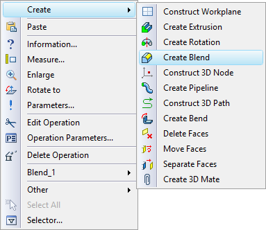
The command "3DE:Create Blend" is used for blending edges. The command can be called in one of the following ways:
Icon |
Ribbon |
|---|---|
|
3D Model → Create → Blend → Edge |
Keyboard |
Textual Menu |
<3DE> |
Operation > Blend >Edge |
The command can also be called from the context menu on the right-click ![]() after selecting any of the elements appropriate for blending. These are faces, edges, loops, vertices and operations.
after selecting any of the elements appropriate for blending. These are faces, edges, loops, vertices and operations.
The following sequence of actions is to be done for creating a blend operation:
1. Select elements to blend.
2. Define blend parameters.
3. Confirm the operation.
How to select objects
Upon launching the command, a general-purpose option is active in the automenu. It allows selecting any appropriate objects for the operation:
![]() <N> Select Faces, Edges, Vertices
<N> Select Faces, Edges, Vertices
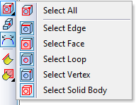
The drop-down list of the given option contains the filters for selection of various 3D objects: edges, faces, loops, 3D vertices and bodies. Selection of elements is done in the 3D window. Move the cursor over the desired object. The element to be selected will then get pre-highlighted, and a tooltip will pop up next to the cursor identifying the element. Click |
|
Let us consider, in more detail, the use of each selection filter from the list of the ![]() option:
option:
Select Edge ![]() . This option sets the system for edge selection. It can be used together with the smooth chain selection mode, activated by the option:
. This option sets the system for edge selection. It can be used together with the smooth chain selection mode, activated by the option:
|
<S> |
Smooth edge chain selection mode |
A smooth chain is a set of edges making an open or closed continuous smooth curve (a C2 curve).
When using this mode all edges are selected automatically that can make a smooth chain together with the edge being selected.
Select Vertex ![]() . This option sets the system for selection of vertices. When selecting a vertex, all edges meeting at this vertex are selected. The zero offset from the selected vertex is automatically defined for the thus selected group of edges. If the directions of the meeting edges disagree, the “Start” and “End” parameters are synchronized so that for all edges the offsets are defined in the selected vertex.
. This option sets the system for selection of vertices. When selecting a vertex, all edges meeting at this vertex are selected. The zero offset from the selected vertex is automatically defined for the thus selected group of edges. If the directions of the meeting edges disagree, the “Start” and “End” parameters are synchronized so that for all edges the offsets are defined in the selected vertex.
This filter can be used in the mode of selection of vertices without automatic selection of edges. This is necessary for creating some special cases of blend, such as Y-shape blend and processing of vertices joining the edges of opposite convexity. Here is the option turning this mode on and off:
|
<Z> |
Allow vertex selection without edge selection |
In this way, selecting a vertex does not cause selection of edges. The selected vertex is added to the list of elements for blending.
Select Loop (a closed contour) ![]() . The system prompts us to select the closed contour of edges (loop). The user is not required to define start and end of the edges belonging to a closed loop. In this case, the blending parameters are set simultaneously for all edges. Individual parameters can’t be defined for any single edge in the loop. By the convention, the first face of the blend is considered the face surrounded by the loop. This will be also the first face for each edge in the loop. Remembering this convention is important when creating chamfers.
. The system prompts us to select the closed contour of edges (loop). The user is not required to define start and end of the edges belonging to a closed loop. In this case, the blending parameters are set simultaneously for all edges. Individual parameters can’t be defined for any single edge in the loop. By the convention, the first face of the blend is considered the face surrounded by the loop. This will be also the first face for each edge in the loop. Remembering this convention is important when creating chamfers.
Select Face ![]() . The system prompts us to select the faces. As in the previous case, same parameters are used for all edges of the selected face. The selected face is also considered the first face of the blend for each edge.
. The system prompts us to select the faces. As in the previous case, same parameters are used for all edges of the selected face. The selected face is also considered the first face of the blend for each edge.
Select Solid ![]() . The system prompts us to select the bodies (operations). Upon selecting an operation, all edges of the solid appropriate for blending are added to the selected list. This is a very different way from the two previous options. It allows defining individual settings for different edges of one selected solid.
. The system prompts us to select the bodies (operations). Upon selecting an operation, all edges of the solid appropriate for blending are added to the selected list. This is a very different way from the two previous options. It allows defining individual settings for different edges of one selected solid.
The objects selected for blending are added as a list to the special fields of the dialog of the operation's properties. Edges, faces and loops are added to the list on the “Edges” tab. Vertices selected with the help of the The user can cancel the selection of objects for blending with the help of the [Delete] button in the command's properties window or by repeated selection of elements in the 3D window. |
|
Defining operation parameters. Using draggers
The operation parameters can be defined at any step of creating the operation. The operation parameters can be defined in the Property window, which supports the transparent input mode, or the parameters dialog box, that requires confirmation before the changes take effect. The property window works together with helper graphic widgets called "draggers".
The property window of the "Blend Edge" operation consists of three sections: "General Parameters", "Overflow Processing", "Options". Some of the controls in the parameter window may get hidden or replaced by others. This depends on the type of blending or the type of the element being processed (edge or vertex).
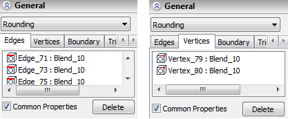
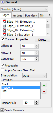
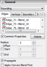
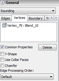
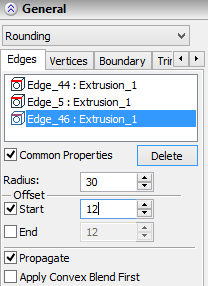
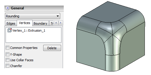
We recommend to begin defining parameters after selecting the elements for blending. As was mentioned above, the selected edges, faces, and loops are displayed in the list on the “Edges” tab. The vertices selected with the help of the ![]() option (without selection of edges) are added to the list on the “Vertices” tab. Blending parameters can be defined for a particular object by selecting it from these lists. Originally, blend properties are set same for all elements. This is signaled by the flag “Common Properties”. Individual blending parameters can be defined for each element in the list after clearing this flag.
option (without selection of edges) are added to the list on the “Vertices” tab. Blending parameters can be defined for a particular object by selecting it from these lists. Originally, blend properties are set same for all elements. This is signaled by the flag “Common Properties”. Individual blending parameters can be defined for each element in the list after clearing this flag.
The blend type can be selected from the pull-down list. Depending on the blend type, the appropriate controls appear for defining parameters attributed to this type.
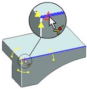
Using draggers
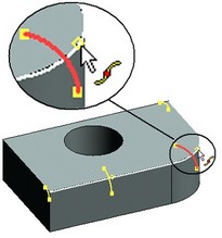
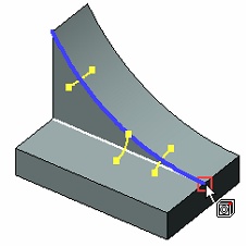
Draggers are helper graphic widgets for dynamically defining main numerical parameters of the blend in a transparent fashion. Draggers appear automatically once the objects for blending have been selected. Their quantity, look and size depend on the type of rounding, the kind of selected objects and the type and values of the parameters modified by the draggers.
The draggers are displayed in various colors. By default, the active dragger (the one being manipulated by the mouse) is drawn red, all the rest (inactive) are yellow.
Using draggers for blending of many edges at once may cause delays in system responses, especially on low-performance computers. To speed up the system in such cases, the draggers can be turned off. This is controlled by the respective checkbox item in the "Options" section of the property window.
The following paragraphs describe all kinds of manipulators for each blend type.
Defining constant-radius rounding
1. Select objects for rounding. It is convenient to do this first. However, if necessary, objects can be selected at any step of defining the operation.
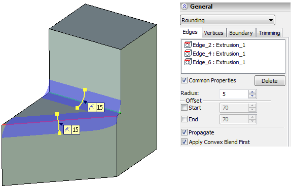
2. Set the type of blend to "Rounding" in the pull-down list.
3. Set the radius of the rounding. Initially, it can be roughly set by the draggers.
The draggers for marking and modifying the rounding radius are displayed at each selected edge: one per a straight edge, two per a curved edge, and four on each closed edge.
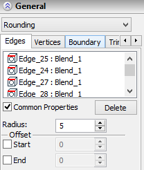
Initially a single value of the radius is set for all edges processed by one operation. Moving one dragger results in all the rest instantly adjusting by the same amount. To define individual properties of some edge, select it in the list and unset the flag "Common Properties". Then, an individual value of the radius can be entered in the "Radius" input box. The radius-controlling draggers on this edge will become independent from the rest.
4. Confirm the operation creation with the button ![]() .
.
Defining variable-radius circular rounding
1. Select edges for rounding.
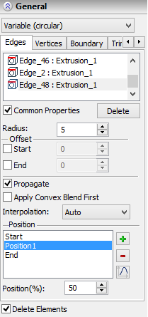
2. Select the type "Variable (circular)" in the pull-down menu of the property window. The necessary controls will appear for defining the rest of parameters. 3. Next, the set of intermediate points needs to be defined, and radii specified in each point. Important: initially, the system tries to compose one chain (not necessarily smooth) of all selected edges. If this is impossible, then several chains will be composed. Within each edge chain, the set of points is distributed along the full length of the chain. The system can automatically compose the chains from the edges marked with the flag "Common Properties". If the flag "Common Properties" is off for some edge then the whole set of points will be distributed along this edge only, and stay strictly specific to this edge. If several edges are processed simultaneously that make a smooth chain, while the "Common Properties" flag is off, make sure the radii on each side of the edge joints are equal. |
|
The list of points defining the radii is input in the ![]() pane. Initially two points exist in the list – "Start" and "End", at 0% and 100% of the edge (chain) length respectively. These points are always present, and their positions are not modifiable.
pane. Initially two points exist in the list – "Start" and "End", at 0% and 100% of the edge (chain) length respectively. These points are always present, and their positions are not modifiable.
To add a new intermediate point, press the [Add] button. A new dragger will appear on the edge controlling the new point position and the blending radius at this point. By moving the dragger handles, one can vary both parameters of the point being processed.
The current position of the intermediate point is displayed in the "Position (%):" input box. An exact value can also be entered here from the keyboard.
To adjust the radius value at an intermediate point, first select this point from the "Position" list. Then, the radius value can be entered in the "Radius:" field.
Position of the points may be specified with the help of a graph. Use ![]() button in the properties dialog for this purpose. This button will open the graph editing window. The range of definition by X is 0-100 corresponding to the percentage from the length. The value area is limited with positive numbers only. See more details on operations with graphs in chapter "Graphs".
button in the properties dialog for this purpose. This button will open the graph editing window. The range of definition by X is 0-100 corresponding to the percentage from the length. The value area is limited with positive numbers only. See more details on operations with graphs in chapter "Graphs".
4. Specify the type of the radius change – “Linear”, “Smooth”, or a special option – “Auto”;
The type of the radius change is selected from the drop down list of the parameter “Interpolation”. The option “Auto” is set by default. In this case:
a.if for the current rounding only start and end points are specified, the radius change will be calculated by the linear algorithm;
b.otherwise (when internal points are specified) a smooth algorithm of the radius change is applied.
5. Confirm the operation creation by pressing the button ![]() .
.
Defining variable-radius elliptical rounding
1. Select edges for rounding.
2. Select the type "Variable (ellipse)" in the pull-down menu of the property window. The necessary controls will appear for defining the rest of parameters.
3. Next, the set of intermediate points needs to be defined, along with the offsets and rho (convexity) values at each point.
Elliptical rounding is based on special points, just like the previous, variable-radius, rounding. The point defining techniques are similar to those described for the variable-radius circular rounding (excluding possibility of setting positions of intermediate points with a graph). The difference of this blend type is in the ways of defining the shape of rounding.
In this way of blending, two offsets are defined at each point defining boundaries of the blend at the given cross section, and the rho (convexity) value of the cross section curve.
In general, without use of draggers, the following procedure is recommended for defining the blend surface parameters at the points:
Select the desired edge in the list of selected elements.
Enter the point list pane.
Add required number of intermediate points; define their position on the edge or chain of edges.
Go through the points of each edge, defining the offsets and rho (convexity) values.
4. Specify the type of the radius change – “Linear”, “Smooth”, “Auto” (in the same way as for creating variable-radius circular rounding);
5. Confirm the operation creation by pressing the button ![]() .
.
Defining chamfer
1. Select edges for the chamfer.
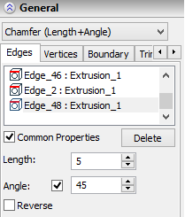
2. Select the blend type "Chamfer (Offsets)" or "Chamfer (Length+Angle)".
3. Define chamfer parameters. The set of parameters is different for various chamfer types. The easiest way is to roughly set up values using the chamfer dragger. Exact values can be entered in the property window.
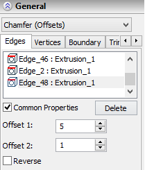
When defining the offset chamfer, one dragger handle defines the first offset, the other second. The edge direction determines which side of the edge is the first, and which is the second. The edge direction can be flipped by toggling the "Reverse" flag. This flag works individually on each edge and does not depend on the "Common Properties" setting.
When defining chamfer by angle, the second dragger handle will be driving the "Angle" parameter. A special flag can be set in the property window against the "Angle" item that will block angle modification by the second dragger handle. In this way, moving either dragger handle will drive the first offset while keeping the angle fixed.
4. Confirm the operation by ![]() .
.
Manipulating the special blend options
Topology deletion. A special flag "Delete elements" in the property window controls topology deletion. This functionality is available for all types of blend.
Overflow Processing. Processing overflows is defined by the respective flags at a separate section of the window. All these flags are turned on by default. With such settings, the system attempts to apply all possible overflow processing types in the order the options appear. An algorithm of processing zones with small curvature radius is selected from the combo box.
Propagating blend on tangent edges. The smooth chain selection functionality is available for all types of rounding. The edges smoothly adjoining to the selected one will be also blended. Blend propagates in the order of the elements on the "Edge" pane. This functionality searches for a smooth continuation of the currently blended edge. A smooth chain may exist originally or form as new edges are created on the blend boundary. In the case of successfully defining a smooth chain the system attempts to propagate the blend along the whole chain.
The option ![]() described above has a similar purpose. However, when selecting an edge with this option, all elements of the identified chain are placed on the "List" pane. When using the "Propagate" flag, the list may not contain all edges of the blended chain, rather, could be just one edge. This is important in view of possible topology changes of the model when the smooth chain contents may change. In this way, one can select just a single "most stable" edge of the whole chain to be blended.
described above has a similar purpose. However, when selecting an edge with this option, all elements of the identified chain are placed on the "List" pane. When using the "Propagate" flag, the list may not contain all edges of the blended chain, rather, could be just one edge. This is important in view of possible topology changes of the model when the smooth chain contents may change. In this way, one can select just a single "most stable" edge of the whole chain to be blended.
Defining Y-Shape blend
1. Select edges subject to blend.
2. Select the vertex intended for the Y-Shape blending. To select a vertex without selecting edges use the automenu option:
![]() <Z> Allow vertex selection without edge selection
<Z> Allow vertex selection without edge selection
3. In the list of selected objects to be blended, highlight the vertex and set the "Y-Shape" flag for it.
If Y-Shape blend can't be constructed in the given vertex, the system will attempt conventional blending, ignoring the "Y-Shape" flag.
4. Specify the blending radius for the edges. This can be done by using the respective draggers or by entering in the “Radius” input box that becomes accessible after highlighting the edge in the list of selected edges on the “Edges” tab.
5. Confirm the operation by ![]() .
.
Defining chamfer at the vertex
1.To create a chamfer at the vertex, it is the most convenient to follow the algorithm described below:
1.Selection of objects (edges) for blending is performed by choosing the vertices at which offsets are expected to be specified. Selection of edges can be done by pointing at the vertex only if the ![]() mode is disabled.
mode is disabled.
The list of selected edges on the “Edges” tab of the properties window will include only the edges adjacent to the vertex. The vertex itself is not included. The blend radius for the edges does not need to be specified (keep the default value).
2.Select the vertex at which the chamfer is expected to be created with the help of the ![]() option.
option.
3.In the list on the “Vertices” tab, point at the vertex and enable for it the “Chamfer” flag.
4.Confirm creation of the operation by ![]() .
.
Defining a blend with spherical vertices and offsets form vertices
The vertex offset parameters can be defined for all types of edge blends, except chamfer. The following steps are recommended if planning to make a blend with vertex offsetting:
1. Selection of objects for blending (the edges) is to be done by vertex selection where the vertex offsets are expected. Make sure to turn off the option 2. Specify the offset values. This can be conveniently done using the offset-driving draggers. |
|
Initially, the flag "Common Properties" is set for all edges. This allows entering equal offsets for all edges meeting at the vertex. Modifying one offset causes all the rest edges assume the same value. This is seen by the appearance of all offset-driving draggers.
To define different values of the offsets, turn off the flag "Common Properties". This does not have to be done for all edges at once. Individual properties can be set only for some particular edges by turning off only their flag "Common Properties". For the rest, the common properties will still be used.
The offset values are displayed in the property window under the items "Start" or "End" - depending on where on the edge is the offset. Exact values can be typed in these input boxes as well. Before each item there is a checkbox activating the "Offset" parameter at the start or at the end of the edge. As we were selecting the edges in the described way (by selecting the vertex), the system was automatically flagging the appropriate ends for the edges meeting at the vertex. This was done according to each edge orientation in the group. Some edges have the offset at start, others at the end, so that all of them have the offset from the vertex where they meet.
For ultimate control, one can manually define the offset parameters using the described flags. Meanwhile, draggers can be used for previewing offset characteristics.
3. Define the radius values for the edges to blend. Any blend type is supported, except for chamfer. The blend parameters are assigned to edges in one of the described above ways, depending on the blend type.
4. If it is required to construct the blending without transitional surfaces, it is necessary to additionally select the vertex itself. This can be done by enabling the ![]() option. The selected vertex will be added to the list on the “Vertices” tab. For the selected vertex the “Use Collar faces” flag will become.
option. The selected vertex will be added to the list on the “Vertices” tab. For the selected vertex the “Use Collar faces” flag will become.
5. Confirm the operation by ![]() .
.
Processing vertices joining the edges of different convexity
This special processing is only applicable for constant-radius rounding.
Suppose, three edges meet at a vertex, two of the same convexity, and the third one of the opposite. To blend the two edges of the same convexity with vertex processing, additionally select this joint vertex. To select the vertex alone, use the following special option,
![]() <Z> Allow vertex selection without edge selection
<Z> Allow vertex selection without edge selection
With the option active, select the vertex. The vertex will be added to the "Vertices" pane of the property window. The rest of parameters are defined in the way described for the "Rounding" blend type.
Defining the order of blending of edges upon blending of vertices
To enforce automatic blending of a vertex, in the general case, it is necessary to select all edges meeting at the given vertex. This is sufficient for creation of blending. However, if the option for selection of the order of blending of edges is expected to be used, it is required to additionally select the vertex itself with the help of the ![]() option. For the selected vertex, the “Edge processing order” parameter will become accessible.
option. For the selected vertex, the “Edge processing order” parameter will become accessible.
An approximate algorithm for creation of the blending in this case is the following:
1.Select objects (edges) for blending. It is possible to select the edges explicitly or indicate the vertex at which they meet, when the 2.Specify the value of the radius for the edges to be blended. Specification of parameters of blending for edges is carried out according to the general rules described above for the type of blending being employed. 3.If the form of the blending geometry at the vertex is expected to be controlled, it is necessary to additionally select the vertex itself. This can be done by enabling the 4.For the selected vertex the “Edge processing order” parameter will become accessible. From the drop-down list it is possible to select one of the following options: “By default”, “At first convex”, “At first concave”, “At first with minimum convexity”, “At first with maximum convexity”. 5.Confirm creation of the operation by |
|
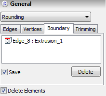
Defining intact edges
To specify intact edges, use the option:
|
<L> |
Select intact edges |
Selected edges are added to the list on the “Boundaries” tab.
Defining bounding geometry
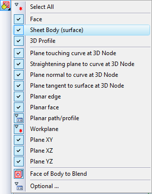
To specify bounding geometry, use the option:
|
<T> |
Select element defining the surface or the cut-off plane |
The drop-down list of this option contains a combination of filters for selection of various 3D objects that are capable to define the cut-off surface. The selected object is added to the list on the “Cutoff” tab.
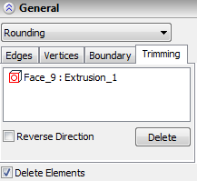
Additional flag called “Reverse direction” allows us to change the location of the blending being created with respect to the specified bounding plane/surface.
Defining the order of creation of blending when the blend surfaces overlap on several edges
The order in which the overlapping blend surfaces are created can be controlled with the help of the “At first concave” flag on the “Edges” tab of the command's properties window.
Diagnostics Mode
The special diagnostics mode in the edge blending operation allows a user to determine the possibility and causes of the error appearance while creating the blend.
The absence of errors in the diagnostics mode is the necessary but not the sufficient condition for successful blend creation. The absence of errors in the diagnostics mode does not guarantee the successful completion of the operation creation.
The following option of the automenu is used for entry into the diagnostics mode:
![]() <D> Diagnostics
<D> Diagnostics
This option is available for selection right after selecting the objects for blending.
In the preview mode and in the mode of viewing the changes made by the operation the option for starting the diagnostics mode is also available if, in these modes, the problems arise upon the model regeneration.
When entering into the diagnostics mode, the system automatically analyzes the specified objects and the blend parameters. The objects, the blending of which may cause problems, are marked in the list with a exclamation point – ![]() .
.
In the diagnostics mode in the system's properties window all fields except the list of the blend objects are locked.
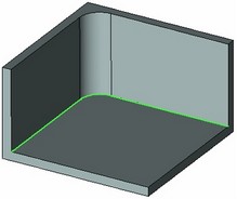
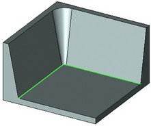
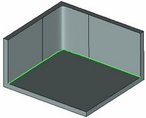
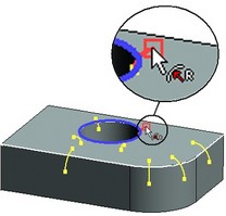
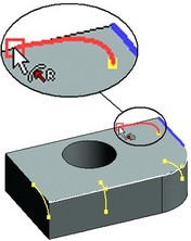
When selecting a marked object (edges, vertices, faces) from the list, the edges identified with the selected object are highlighted on the model in the 3D window. Also, a marker with the text describing the error appears. In some cases, the geometric element of the 3D model creating the problem is marked additionally. A user can select several objects at once to evaluate several problems simultaneously. To do it, make the selection with the help of <Shift>+ |
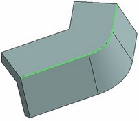
The blendable edges are shown with green color, whereas the geometric element of the model leading to a problem is shown with yellow color |
If in the diagnostics mode several faulty objects are selected from the list, then selecting the marker with the help of ![]() without moving it at a significant distance will cancel the selection of the remaining objects.
without moving it at a significant distance will cancel the selection of the remaining objects.
When exiting the diagnostics mode, the marking of the faulty elements with the special icons in the list is retained for convenient correction of the discovered problems.