The face blending operation lets create a blend surface between one set of smoothly meeting faces to another. The sets of the blended faces are not required to have common edges (intersect). Blending can be done over solid bodies, as well as sheet bodies. The command has numerous options for controlling the shape of the blend surface, defining trimming conditions, bounds, etc. Do not consider this operation as an alternative to the edge blending operation. These two approaches have their advantages and limitations, well complementing each other.
Main concepts. Operation capabilities
The two sets of faces for blending are conventionally called the right and the left wall. In most general case, these can be arbitrarily positioned in space and have arbitrary geometry of the surface. The system constructs the blend surface between the right and the left wall in several steps.
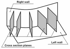
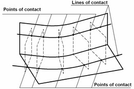
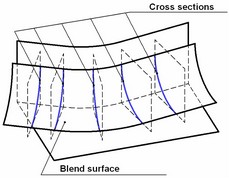
Step 1 Step 2 Step 3
●First, the set of planes is computed for holding the blend cross sections. The position of each plane depends on the existence and the shape of the auxiliary direction guide, as well as on the computational algorithm of a particular blend type. One can specify various blending effects by manipulating the orientation of the cross section planes.
●Next, two points are defined on each plane that will be the bounds of the future blend surface. One point belongs to the right wall, the other – to the left. These will be referred to as the points of contact of the blend surface. The sets of the points of contact on the right and left walls make the two lines of contact. The position of the points in each cross section depends on the shape and mutual situation of the walls, as well as on the computational algorithm of the particular blending mode.
●Finally, the system computes each cross section of the blend surface spanning the two points of computed in the previous step. The shape of the blend cross section depends on the positions of the points of contact and on the selected geometrical algorithm.
●The final result may also be affected by a number of additional functions and boundary conditions.
Direction Guide
The direction guide defines positions of the blend cross-section planes. 3D paths can be used as guides. The direction guide is used for constructing most types of blends. Often, when all parameters appear to be defined yet the confirmation button is inaccessible, most probably the direction guide is needed.
If the guide is too short for constructing the whole blend surface, the system extends the guide by straight segments tangent to the 3D path at the ends. If the guide is longer than required, the system will attempt automatically define the necessary portion if the 3D path.
Sometimes, the operation can be created without use of a guide, as in the case of simple rolling ball blending.
Blend Types
There are two types of blends. Each type involves its own algorithm of constructing cross section planes for computing the blend surface.
Rolling ball blend
In this type of blending, the cross section planes are made orthogonal to the right and left walls. This blend type does not require a guide in the "Constant radius" and "Constant width" modes.
In the "Constant radius" mode, a notional ball of the specified radius defines the points of contact as it touches the right and left walls. This ball "rolls" all the way along the right and left wall and leaves two lines of contact. The cross section planes pass through the points of contact and the center of this notional ball at a given instant.
Rolling ball blend is the only type supporting the "Constant width" mode. In this case, the system automatically positions the cross section planes for best fit to the requirements of the specified blend mode. The guide is not required in this case either.
The "Variable radius" mode always requires using a guide. A current point on the guide is used to define the nearest points on the blended surfaces. Normals to the right and left wall surfaces are constructed at these points. The cross section plane passes through the current point on the guide. The plane normal is computed as a cross product of the two surface normals from the above. In the special case of flat wall surfaces, true to say that the cross section plane passes through the current point on the guide and is oriented orthogonal to either wall.
Disc blend
A plane is constructed orthogonal to the guide through each point on the guide. A current blend surface section is computed in each such plane.


Rolling ball blend Disc blend
Isoparametric blend
This is an advanced type of blend. Isoparametric blend is a special type provided for turbine design. It is used to make a blend between a turbine blade and a base. The isoparametric blend is best for this kind of parts.
The isoparametric blending is similar to the disc type. However, the blend cross-section planes are oriented along the isoparameter lines of the blade surface in this case. Because of this, the blade surface ought to be necessarily the first set of faces (the left wall).
The direction guide must lie on the left wall (the one that defines the isolines). A dependency is established between the points on the guide and the blade surface. Then the specified cross-section blend surface is constructed tangent to the current isoline.
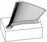

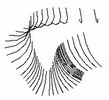

Rolling ball blend Isoparametric blend
The diagram on the left-hand side shows a rolling-ball blend with self-intersection zones. The right-hand side diagram demonstrates an isoparametric blend with no flaws.
Blend Modes
Blend modes define the ways of computing the blend surface bounds in the current cross section. Only the bounding points (points of contact) are computed in the cross sections of the blend surface. What will be constructed in between the bounding points depends on the chosen shape of the blend surface.
Constant radius
In this mode, the blend surface is constructed of the constant shape across the extent of the blend. The term "radius" in the mode name is just a convention. In fact, variations of this type include, besides the conic-shape roundings, chamfers and surfaces of smooth curvature (see below "Shapes of blend surfaces"). This depends on the specified blending shape. With the conic shape of the cross section selected, a surface is constructed with each cross section being a circular arc of a specified radius.
Variable radius
This blending mode supports blend surfaces with the shape parameters varying across the extent of the blend. All cross section parameters are controlled via special auxiliary points distributed along the blend surface. The points of contact are computed in the variable-radius mode based on two ranges defined for each such auxiliary point. The same approach is used for computing the points of contact by the ranges, as in the command "Blend Edge". The same chapter (see the topic "Variable-radius elliptical rounding") describes and illustrates the approach in details. The following is different in variable-radius blending by the "Blend Face-Face" operation from the variable-radius elliptical rounding by "Blend Edge". First, it is the way of constructing the cross section planes. Second, it is availability of other cross section shapes (besides the conic one).
Constant width
In this blending mode, the blend cross sections are constructed based on the constant chordal width condition. These are the chords connecting the points of contact in cross sections. This type of blending is especially desirable when the angle between the blended faces varies across the extent of the blend. In this case, one may want to specify approximate amount of cross section additional material to be maintained along the blend.
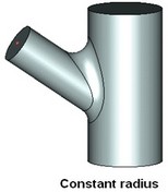
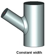
"Constant width" mode only works with "rolling ball" type blend.

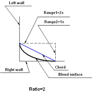
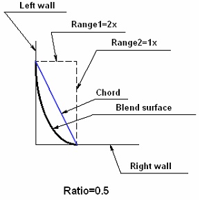
In this blending mode, the parameters of the shape are the chordal width and the ratio of the ranges for the bounding points of the blend surface. A ratio of ranges other than 1 makes a blend with a constant chordal width and asymmetrical cross section.
In constant width mode, the system automatically determines the shape of a conic cross section.
Shapes of blend surfaces
Three different shapes of blend surfaces are supported.
Conic
Conic is one of the shapes found in sections of a cone by a plane. These are a circle, an ellipse, a parabola and a hyperbola. In the constant radius mode, if "conic" shape is selected then the blend cross sections are arcs of the specified radius. In the variable-radius mode, the shape of a cross section is dependent on the "skew" parameter representing the rho value of a conic. Different values of this parameter yield an ellipse, a parabola and a hyperbola.

Chamfer
The chamfer-type blend cross section is defined as follows. The points of contact, computed in each cross section, are connected by a straight line. Chamfer is supported for all blend types and blending modes.

Continuous curvature shape
This way of blending provides continuity of the surface curvature where the blend surface meets the walls. In other words, the blend surface has the same curvature at the points of contact as the respective wall.
In "Constant radius" and "Constant width" blending modes the shape of the surface depends on a single "Softness" parameter controlling the smoothness of the transition from one wall to the other.
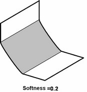

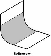
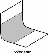
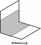
The value of the softness greater than zero is allowed, with the maximum unlimited. With the softness values approaching 0, the blend cross section becomes closer to a chamfer. However, if a true chamfer is required then the "Chamfer" setting for the blend shape is recommended instead.
The "Variable radius" mode provides two parameters for controlling the blends with continuous-curvature cross sections – "Offset" and "Depth".
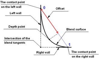
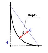
These two parameters together define the deepest point on the current blend cross section – the "Depth point". The "Offset" defines the position of the "depth point" between the two contact points. The parameter varies from 0 to 1, exclusive. The depth point approaches the left wall, as the offset approaches zero and the right wall with the offset approaching one. The "Depth" defines the position of the "depth point" between the chord connecting the two points of contact, and the intersection of the wall tangents. The parameter varies between 0 and 1, exclusive. With values near 0, the "depth point" approaches the chord between the points of contact, while with values approaching 1 – the intersection of the right and left wall tangencies.
Special Capabilities
Notch
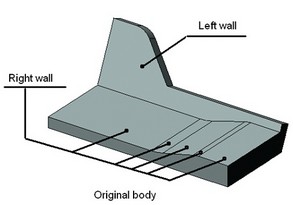
Sometimes, the walls to be blended may include topology insertions (Notches) that cross the line of contact of the blend surface. A special option "Notch" helps identify such insertions and let blending extend in the affected area trimming the blend surface with the faces adjacent to the wall. Without this option, the blending would stop before the affected area, where the line of contact is crossed.
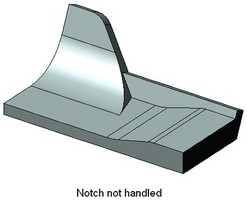
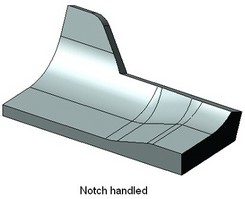


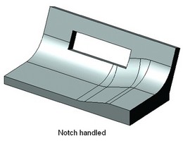
Tangent propagation
This blend option allows extending the blend surface on the adjacent faces smoothly connected to the selected walls. This simplifies the operation definition by letting select just one face per a wall. The system will attempt propagating the blend surface on all adjacent faces as far as possible.
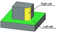
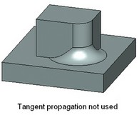
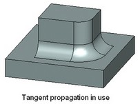
Propagate option can't be used for disc and isoparametric blend types.
Propagate option is applicable when defining boundary conditions (see details below). This allows specifying just one edge for defining boundary conditions if all bounding edges connect in a smooth chain.
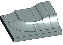

Trimming with planes
Flat faces and workplanes can be used for limiting the blended area. One limit plane divides the blend surface into two parts leaving just one part in the scene. Total of two limit planes can be defined. The two planes will surround from the two sides the central portion of the.
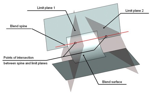
It is important to keep in mind that by dividing the blend surface the limit plane is not trimming it. The blend surface is divided along a cross section plane at the point of intersection between the limit plane and the blend spine.
Blend end trimming
When creating a face-face blend, there is a choice of trimming options for the end boundaries of the blend surface. The geometry of the walls themselves is not disturbed by trimming the blend surface. Total of four trimming options are available:
●No trimming. When trimming is off, the blend surface is extended beyond the ends of either wall.
●Short trimming. The blend surface is trimmed by the end boundaries of the shorter wall.
●Long trimming. The blend surface is trimmed by the end boundaries of the longer wall.
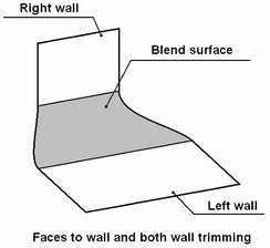
●Faces to wall trimming. The blend surface is trimmed by the end boundaries of both walls. Meanwhile, the side edge of the blend surface is constructed such as to provide tangency with both side edges of the trimming walls.
First three options can be used for blending sheet bodies only.
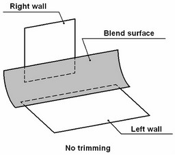
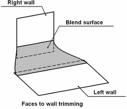
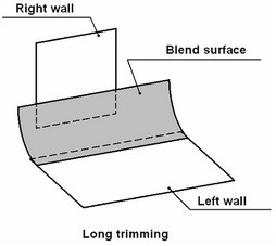
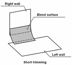
Wall trimming
In addition to blend surface trimming, the walls can be trimmed as well along the line of contact.

Selecting the resulting topology
The face-face blend operation can be stored in the model structure in several topological variations. The choice of a topological solution is combined with the wall-trimming interface (the previous topic). Total of four solutions are available:
●"Separate body" means neither wall will be trimmed and the blend surface will stay as a standalone sheet body. The objects selected for the walls to blend will remain in the model structure in the original state. The blend operation will be represented by a separate sheet body – the blend surface.
●"Trimmed on both walls" trims both walls along the line of contact without attaching the blend to any wall. This solution has a practical meaning only for sheet bodies.
The model structure will reflect the face-face blend operation alone at the top level. The operations whose faces were selected as walls will be written in the model history one level deeper. Meanwhile, the blend operation will be represented by three sheet bodies. This means that if, for instance, the operation 3SD:Divide Solid is applied to the blend then three separate sheet bodies will be created, the two trimmed walls and one blend surface.
●"Attach to the left wall" trims both walls and attaches the blend surface to the walls. If blending was done between two different sheet bodies then these bodies are united into one by the blend. The operation used as the left wall will further be used as the reference in the model structure.
●"Create body" trims both walls, adds the blend to the walls and creates a solid body if possible. This solution can only be used together with the "Faces to wall" trimming option. This option is similar to the previous. The specific of this option is the system attempting to create a solid body. This is done if a check is satisfied for the resulting geometry to form a closed volume.
Solution using an adjusting point
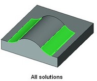
In some cases, several blend surfaces can be constructed for the same set of walls. One can accept them all. However, a particular solution can be specified. The system accepts the solution nearest to a selected node.


Processing curved zones (Inside tight)
The algorithm's for processing curved zones allow creating blend's in the areas where the value of the curvature radius of the sidewalls is less than the blend radius. This option is available only for rolling ball blending by a conical section of a constant radius. This functionality is described in more details in the chapter "Edge blend".
Boundary conditions
Tangency to faces
In the cases when a blend surface overflows beyond the blended faces (of the right or left wall) then the system can adjust the blend surface to keep edges overflown by the blend surface. This results in shifting the line of contact of the blend surface in the area of the edge overflow to actually make it coincide with the edge. The blend surface adjustment is done while maintaining the tangency condition at the wall surface in the points of contact.
If the blend surface can't be fit within the extent of the walls, two types of constraints can be specified - "One-face tangent" or "Two-face tangent".
The boundary condition is defined by selecting an edge or a set of edges belonging to one or another wall, called "holdline".
If one face tangency is elected then the opposing line of contact of the blend surface is not disturbed. It will satisfy the defining rule of the shape of the surface (as, for instance, the radius). If two-face tangency is elected then the opposing line is distorted symmetrically.
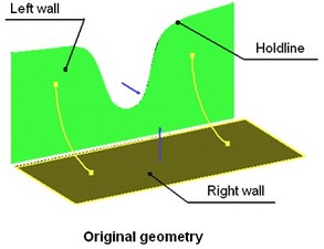
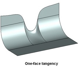
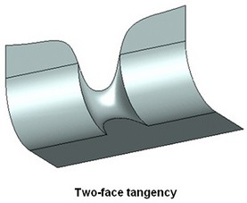
Inverted tangency to faces
The boundary condition is defined by an edge or a set of edges belonging to one of the walls (the holdline). With too small radius values, when the blend surface can't be constructed, the system shifts the line of contact to the holdline. The blend surface is tangent to the faces of the wall along the line of contact. If the back tangency to one face is elected, then the opposing line of contact of the blend is not disturbed. It will satisfy the defining rule of the surface shape (as, for instance, the radius). If inverted tangency to two walls is elected then the opposing boundary is distorted symmetrically. Thus, the blend surface is no longer defined by the radius. Rather, it is deformed by the boundary conditions wherever imposed.

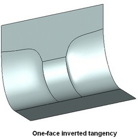
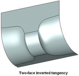
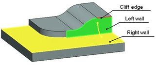
Cliffedge
This is the "sharp edge" overflow, when tangency is not maintained at the bounding edge.
The edge overflown by the blend surface is left unchanged. The blend surface is constructed without distortions in such a way that the cross section spans between the wall and the line of contact of one side and the cliffedge on the other side, without altering the guiding rule of the cross section shape.
To understand this, consider a simple example of a spherical blend with a constant radius. Imagine a ball of the given radius rolling on one wall, keeping contact with the sharp edge on the other wall.

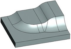
With this constraint, tangency is not provided for the blend surface along the cliffedge, however, the shape of the sections is not distorted and is constructed by the specified rule across the blend surface.
Operation defining steps
The operation creating command can be called via one of the following ways:
Icon |
Ribbon |
|---|---|
|
3D Model → Create → Face-Face |
Keyboard |
Textual Menu |
<3DF> |
Operation > Blend > Face-Face |
The property window and the automenu are used for handling the command and defining necessary components. These work simultaneously and enhance each other. The state of the automenu depends on the operation defining stage and on the purpose and type of the objects being selected. The object selection modes can be manipulated via either the automenu or the property window.
To create the operation, follow the following steps:
1. Select first set of faces (the left wall)
2. Select second set of faces (the right wall)
3. Specify blend type (if necessary)
4. Select the spine (if necessary, depending on the blend type)
5. Specify blending mode (if necessary)
6. Specify the shape of the blend cross section (if necessary)
7. Specify geometrical parameters of the blend cross section
8. Specify boundary conditions and overflow processing (optional)
9. Confirm operation creation
Using draggers and decorators
As the face-face blend operation is being defined, the parameters can be specified and various objects selected in the 3D window with the help of auxiliary elements. These elements help quickly review and modify the configuration of the operation being created. Their quantity, shape and size depend on the defined properties of the operation, on the purpose of the selected objects and on the type and values of the parameters controlled thereby. The elements that control parameters dynamically are called "Draggers". The elements that merely display some or other operation properties are called "Decorators".
Draggers are displayed in various colors. By default, the active dragger (the one driven by the mouse at the moment) is drawn red, all the rest - yellow. Decorators are drawn blue by default.
Draggers are used for quick reviewing of the result and correcting it, therefore, the shape follows the actual blend surface with limited accuracy. Dragger does not make an account of all details of the cross section in the case of the surfaces with continuous curvature and is not responding to such settings as "Convexity", "Softness", etc.
Using draggers with numerous active objects on a low-performance computer may cause delays in the system response. To speed up workflow in this situation, the draggers may be turned off. The off switch for the draggers is located in the "Options" section of the property window.
The following topics review all types of manipulators and decorators for each flavor of face-face blend.
Selecting a set of faces
Normally, the operation is defined beginning with selecting the sets of faces between which the blend will be constructed. The left and right-wall sets are formed when one of the following automenu options is active:
![]() <L> Select left-wall face
<L> Select left-wall face
![]() <R> Select right-wall face
<R> Select right-wall face
Switching between the options is done by pressing an icon button in the automenu. Turning on an option automatically activates the respective tab on the property window. The list of selected faces of the right or left wall is displayed in the provided pane under the tab tag. Switching between the tabs of the property window also activates the appropriate options for face selection.

Face selection is done using the mouse in the 3D view window.
The selected faces of the left wall are highlighted in green by default, the right ones - yellow. Settings of the highlighting colors are done in the system customization dialog box. The current face highlighting color is reflected in a color box on the tab tag for each set.
A decorator is drawn in the middle of each face, shaped as an arrow, marking the side of the face adjacent to the blend surface. In a general case, two walls make four quadrants, each being suitable for constructing a blend surface. The blend is created in the quadrant pointed at by both arrows.
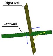
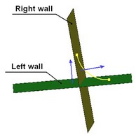
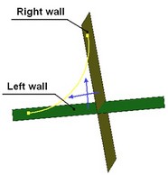
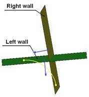
For solid bodies, the direction of an arrow is determined automatically. For sheet bodies, the direction of faces has to be controlled manually by the user. For flipping the system default direction, set or clear the "Reverse" flag.
To exclude a face from a wall set, simply select it in the list in the property window on the respective tab and press [Delete] button.
Blending mode selection
A blending mode can be defined (modified) at any step into the operation setup. The name of the mode is selected in the pull-down menu in the property window. Three modes are available: "Constant radius", "Variable radius" and "Constant width".
"Constant radius" mode settings
In the "Constant radius" mode, the user needs to additionally specify the "radius" of the blend surface. The "radius" input box appears in the property window right after selecting this mode. By default, the system sets the radius equal to 10 units.
![]()
This field is synchronized with the draggers. Depending on the selection of the blend surface shape, the dragger is drawn as an arc or as a line segment (only for chamfer creation). The number of manipulators depends on the number of faces in the right and left wall sets. All manipulators update simultaneously and relate to the same parameter, the "radius".
"Variable radius" mode settings
The "Variable radius" mode brings more additional controls in different parts of the property window. At the bottom of the property window there are standard controls for manipulating intermediate points for variable-radius blend. The special item "Positions" manipulates the list of auxiliary points. The points "Start" and "End" are always included. Other points are named as they are created. Adding and deleting points is done using the buttons [Add] and [Delete]. A point position is specified in a special input box by percentage of the total length of the blend surface.
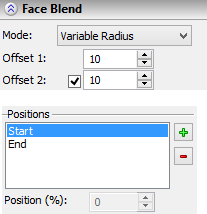
The "Variable radius" mode requires setting two offsets for each auxiliary point. Initially, the system sets the second offset equal to the first one, as indicated by the checked box before the second offset in the property window. With this setting, the two offsets change simultaneously. If the setting is cleared, an individual value can be defined for the second offset.
Positions of the auxiliary points and their offset values can be defined by draggers (see the diagram below).
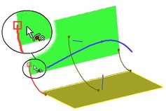
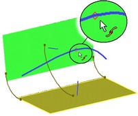
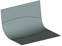
"Constant width" mode settings
The "Constant width" mode requires two numerical parameters – "Width" and "Ratio". By default, the system presets the width of 10 units and the ratio equal to (-1). These fields are synchronized with the respective dragger. Depending on the blend shape selection, the dragger is drawn as an arc or as a line segment (for chamfers only). The number of draggers depends on the number of faces in the right and left walls.

Blend type selection
The type of the blend operation can be selected from the pull-down list in the property window. One can select any of the three choices: "Rolling Ball", "Disc", "Isoparametric". The system sets the rolling ball type by default.

Spine selection
To turn on the spine selection mode, activate the following automenu option,
![]() <S> Select 3D path as guide curve
<S> Select 3D path as guide curve
1Selection of a 3D path is done in the 3D window or in the model tree by the mouse. The name of the selected 3D path is displayed in the property window.

Only one 3D path can be used as a guide. If, say, by a mistake, a wrong path was selected, another one can be selected right away. Selection of a new 3D path cancels the previous, and the last selected path will be used as a guide.
To reject a 3D path selection, use the automenu option:
![]() <W> Cancel Selection of 3D Path as a guide curve
<W> Cancel Selection of 3D Path as a guide curve
Defining the shape of cross section
The shape of the cross section can be selected from the pull-down list in the property window. The list contains three choices: "Conic", "Chamfer" and "Continuous curvature". By default the conic cross section shape is defined. Depending on the blending mode and the selected shape of the cross section, additional controls may appear or hide in the property window for controlling the cross section shape and its geometrical parameters.

Conic cross section settings
When using the "Constant radius" blending mode, no additional settings are requires. In this mode, defining a conic shape makes the blend cross sections become arcs.
An additional "Rho" parameter is defined in the "Variable radius" mode for conic cross sections. The parameter value is defined separately for each characteristic point of the variable blend. By default, the value of 0.5 is assigned to this parameter. In this case, the cross section is a parabola. With smaller values the cross section becomes an ellipse, with greater ones – a hyperbola. This parameter may not be 0 or less and 1 or more.
![]()
In the "Constant width" mode the shape of the conic section depends on the definitions of the mode itself, in particular, on the "Offset" parameter. If the offset ratio is defined equal to 1, then the blend cross section will become a circular arc, otherwise it will be a parabola.
Chamfer settings
No additional settings are required for this shape of the cross section in any blending mode. The points of contact, computed for each cross section according to the chosen mode, are connected by a straight line.
Continuous-curvature cross section settings
The continuous-curvature cross section can only be realized under the rolling-ball blend type. Therefore, selecting this shape for the cross section automatically switches the system into the rolling-ball blend type.
In the "Constant radius" and "Constant width" modes, the shape of the cross section is controlled by the single parameter "Softness". The softness value must always be greater than zero The system default for this parameter is 1.

In the "Variable radius" mode, the shape of the continuous-curvature cross section depends on two parameters – "Offset" and "Depth". Both parameters vary in the range from 0 to 1, exclusive. The default value is 0.5. The values of the parameters are defined separately for each characteristic point of the variable blend.

Defining boundary conditions
All types of boundary conditions are defined along the specially selected edges. To get the edge selection mode, engage the following automenu icon:
![]() <C> Set constraint
<C> Set constraint
Turning on this option automatically activates the "Constraint" tab of the property window. The provided pane under the tag displays the list of selected edges. Switching to this tab of the property window from any other mode activates the edge selection mode as well. The type of boundary conditions can be selected from the pull-down list. Five choices are available: "tangent", "conic", "inverted tangent", "inverted conic" and "cliff". The default offered by the system is "tangent". Each constraining edge requires individual setting of the boundary condition type, in a certain order. First, you need to select a constraining edge in the complete list of edges, and then define (if required) the boundary condition type using the pull-down list.
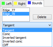
To remove an edge from the list of constraining edges, press [Delete] button in the property window on the "Constraint" tab.
One should keep in mind that constraints can work only in connection with compatible geometrical parameters of the blend surface that are defined by the blending mode and cross section shape.
Thus, if the cross section parameters prevent the blend surface from reaching a holdline then the tangency condition on one or both walls is impossible. Vise versa, if an "inverted tangent" constraint is imposed, then the appropriate "radius" of the blend surface is such that the blend is not reaching the holdline or the wall itself in the zone of the constraint validity.
It follows from the above that often draggers stop working on a blend surface constrained to certain boundary conditions. For example, when creating an "inverted tangent" blend surface that does not reach the walls initially, the draggers are not displayed. Vise versa, when creating a "tangent to walls" blend surface that does not fit amid the walls then the dragger reflects the largest arc fitting amid the walls.
Overflow settings
Notch. Tangent propagation
Attributes are provided in the property window for turning on notch handling and tangent propagation. These parameters are accessible for use with all types of blend.

Limit plane setup
Engage one of the following automenu options in order to select the primary or secondary limit plane:
![]() <F> Set first limit plane
<F> Set first limit plane
![]() <D> Set second limit plane
<D> Set second limit plane
Upon activating the option, workplanes and flat faces will become selectable in the 3D window. Select either in the 3D window or on the model tree using the mouse.
When selecting a limit plane, its decorator is displayed in blue color. The decorator is a rectangle drawn on the limit plane. The size of the rectangle is computed according to the sizes of the right and left walls. Normal arrows are drawn in the corners of the rectangle, pointing toward the side of the blend surface to keep.
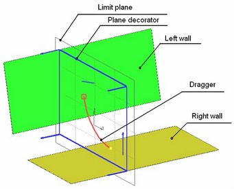
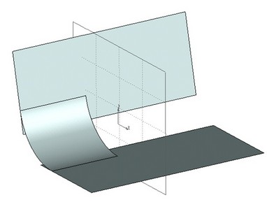
After selecting first or second limit plane, the property window displays the "Reverse" checkbox instead of the previous "Not selected" status, for flipping the "keep" side as indicated by the arrows.

If only one limit plane is to be used then define only the "First" plane. Both the "First" and "Second" limit planes should be defined only when two limit planes are to be used simultaneously.
The following automenu options are provided to reject use of limit planes:
![]() <Z> Cancel Selection of First Limit Plane
<Z> Cancel Selection of First Limit Plane
![]() <X> Cancel Selection of Second Limit Plane
<X> Cancel Selection of Second Limit Plane
End trimming options
The end trimming options for the blend surface can be selected from the pull-down list in the property window. Four choices are available: "Faces to wall", "No trimming", "Long trimming", "Short trimming". By default, the "Faces to wall" option is set.

Defining topology of the resulting geometry
A choice of the resulting topology is selected from the pull-down list in the property window. Four options are available: "Separate body without trimming", "Trimmed on both walls and attach", "Trim, attach and create body" and "Separate body trimmed on both walls". The system default is "Trimmed on both walls and attach".
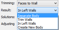
Adjusting solution by a node
If a blend operation results in several sets of blend surfaces, a 3D node can be selected to define the blend set to keep. Selection of the 3D node is done by activating the following automenu option:
![]() <E> Select 3D Node, that defines only one nearest surface as result
<E> Select 3D Node, that defines only one nearest surface as result
Upon selection, the name of the node is entered in the blend operation property window. Next, the user needs to explicitly specify whether to use the solution by the 3D node, or use all obtained solutions. The type of the solution is selected in the pull-down list, containing just two items: "All" and "Use adjusting point". This switch helps quickly alter the solution type without giving up the selection of the adjusting 3D node. |
|
The following automenu option is provided to reject a 3D node selection:
![]() <N> Cancel Selection of 3D Node that indicates the nearest result
<N> Cancel Selection of 3D Node that indicates the nearest result
Creating a "wire-face" blend
To create a "wire-face" blend you must specify:
●set of faces of solid/sheet body as a left or right wall of the blend. The second wall is not defined;
●set of smoothly conjugate edges of the wire body (3D profile, 3D path) as a boundary condition;
●radius of the blend;
●option for the final result topology (only the "Separate body" or "In left wall").
All other parameters of the operation in this mode are not used.
As in the general case, for selecting faces it is necessary to either activate one of the tabs "Left/Right" in the properties window, or use one of the automenu options:
|
<L> |
Select left-wall face |
|
<R> |
Select right-wall face |
The set of edges is defined as a boundary condition. To select the edges, you must activate the "Bounds" tab in the properties window or automenu option:
|
<C> |
Select edge to specify limitation |
Do not change the type of boundary condition.
Option for the final result topology is determined by the "Result" drop-down list in the properties window. For this mode of blend, you can use only two options: "Separate body" and "In left wall".
Option "In left wall" can only be set if the original set of faces belongs to a sheet body. In this case, the resulting body is attached to the original sheet body, regardless of which wall has been set in operation - the left or right.
