The three-face blending operation creates a blend surface from one set of smoothly connected faces to another such set. The blend surface will be constructed tangent to yet another, third set. A typical situation addressed by this operation is creation of a smooth transitional surface between two opposite faces and along the narrow strip of the side surface of thin-wall parts. The sets of faces for blending are not required to share common edges (intersect).
Blending can be performed over solid bodies as well as sheet bodies. This operation can be considered as a special case of the face-face blend, separated into a dedicated command. Since the three-face blend shares many concepts with the face-face blend, first refer to the "Blending faces" section for details on certain terms and concepts.
Main concepts. Operation capabilities
General operation concepts
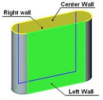
Three sets of faces make the basis of the "Three-face blend" operation. These are called "right", "left" and "center" walls. All faces within each set must meet smoothly. Sharp edges are not allowed. The walls themselves are not required to connect smoothly with each other. All sets of faces can belong either to the same solid body or to one, two or three sheet bodies. Three-face blends can't be created between walls belonging to different solid bodies or mixed sheet and solid bodies.
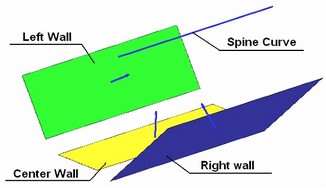
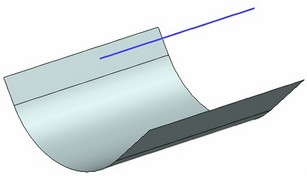
Original configuration Resulting blend
Three-face blend is always disc-type. The cross section planes are the set of planes orthogonal to the guide spine and passing through the three contact points where the blend surface is tangent to the walls. The blend cross section shape is always represented by a circular arc. The cross-section plane intersects with the three walls. The arc in the cross section is constructed in such a way to be tangent to each wall.
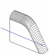
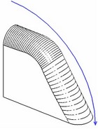
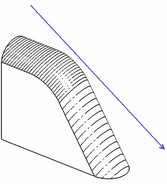
The figures show blend surface geometry dependency on the guide spine
The guide spine is always represented by a 3D path. The spine may not have sharp corners. If the spine is too short for defining all cross sections, it is extended by straight segments tangent at the ends.
If the left and center walls are adjoining then their common edge (the set of edges) may be used as the guide spine. In this case, selection of the guide spine is optional.
In real situations, the edge between the right and left walls often has complicated shape. In such cases, the blend surface may not be successfully created between three faces. Creating a new guide spine may help.
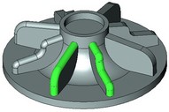
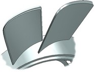
Make a spine of simpler than the edge geometry, just approximately following the edge shape. Let's review two typical examples: Example 1. Required is blending of the side strip of a fan blade. In this case, the system may not use the edge between the left and center walls due to the following reason. The edge has a too small radius in the circled area. The blend cross sections would intersect each other if constructed normal to the edge. An additional spine (a 3D path) helps creating a blend in this case that approximately repeats the shape of the edge yet avoids the mentioned traps. |
|
Example 2. In this example, the left and right walls are cone fragments. The part gets wider in the middle. At the first glance, the edge radius is not too small. However, due to the widening part and edge curving in the opposite direction, the system considerably increases the radius of the blend surface that again results in self-intersections. Using a flat spine of the shown shape helps easily create the blend surface. |
|
Additional capabilities
When blending three faces of a solid body, the result will always be a solid body. When blending sheet bodies, the system automatically analyzes results for the possibility of creating one joint body. With the successful creation of one sheet body, the faces of the right and left walls are trimmed with the blend surface. The center wall disappears. The extents of the blend surface are trimmed to the walls. In the case when it is impossible to merge the result into one body, the system returns a set of separate sheet bodies.
Tangent propagation
Just like in other blend commands, this option provides capability of extending the three-face blend surface onto adjoining faces to the selected walls, if these adjoining faces meet smoothly with the walls and each other. This simplifies the operation definition by letting select just one face per wall. The system will attempt to extend the blend surface on all adjoining faces as far as possible.
When using the tangent propagation option, make sure the guide spine provides correct reference for blend construction across the extent of the blending area.
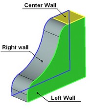
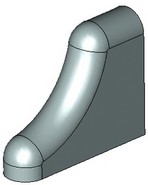
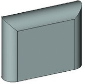
Examples of using tangent propagation functionality.
The edge between the left and center walls is used here as a guide spine.
Operation defining steps
The operation creating command can be called via one of the following ways:
Icon |
Ribbon |
|---|---|
|
3D Model→ Create → Blend → Three Face |
Keyboard |
Textual Menu |
<3DT> |
Operation > Blend > Three Face |
The property window and the automenu are used for handling the command and defining necessary components. These work simultaneously and enhance each other. The object selection modes can be manipulated via either the automenu or the property window.
To create the operation, follow the following steps:
1. Select first set of faces (the left wall)
2. Select second set of faces (the center wall)
3. Select third set of faces (the right wall)
4. Select the spine (if necessary)
5. Specify parameters of the operation (if necessary)
6. Confirm operation creation
Selecting a set of faces
Normally, the operation definition begins with selecting the sets of faces between which the blend will be constructed. The left and right-wall sets are formed when one of the following automenu options is active:
![]() <L> Select left-wall face
<L> Select left-wall face
![]() <C> Select center face
<C> Select center face
![]() <R> Select right-wall face
<R> Select right-wall face
Switching between the options is done by pressing an icon button in the automenu. Turning on an option automatically activates the respective tab on the property window. The list of selected faces of the right or left wall is displayed in the provided pane under the tab tag. Switching between the tabs of the property window also activates the appropriate options for face selection. Face selection is done using the mouse in the 3D view window.
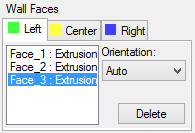
The selected faces of the left wall are highlighted in green by default, the right ones – blue. The set of the center wall is displayed in yellow. Settings of the highlighting colors are done in the system customization dialog box. The current face highlighting color is indicated by the colored box on the tab tag for each set.
A decorator is drawn in the middle of each face, shaped as an arrow, marking the side of the face adjacent to the blend surface. The blend is created on the side pointed at by all three arrows.
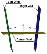
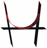
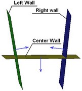
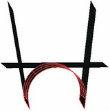
Control over the arrow directions is done via the provided "Orientation" item right of the face list pane on each tab in the property window. Selection is made in the pull-down list. For solid bodies, the direction of an arrow is determined automatically. In this case, the "Auto" option is set for all faces. For sheet bodies, the direction of faces has to be controlled manually by the user.

To change the system default arrow direction, select one of the other two available orientation settings, "Normal" or "Reverse".
To exclude a face from the wall set, simply select it in the list in the property window on the respective tab and press [Delete] button.
Spine selection
To turn on the spine selection mode, activate the following automenu option,
![]() <W> Select guide spine
<W> Select guide spine
Selection of a 3D path is done in the 3D window or in the model tree by the mouse. The name of the selected 3D path is displayed in the "Guide Spine" box of the property window. A pull-down list is provided by the box listing the names of all 3D paths present in this model.

This list is convenient when the user knows the exact name of the 3D path intended as the guide spine. To reject a 3D path selection, pick the "No Guide" entry in this list or use the automenu option:
![]() <K> Cancel selection
<K> Cancel selection
Only one 3D path can be used as the guide spine. If, for example, a wrong path was picked by mistake then another one can be selected right away. Selection of a new 3D path cancels the previous selection, and the last selected path will be used as a guide.
Special features setup
Tangent propagation
To turn on the option of tangent propagation, check the respective item in the property window.
![]()