Holes |
  
|
Holes |
|
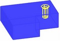
The operation "Hole" helps creating standard holes of various types. The operation capabilities span from creating isolated holes in a single body to cutting holes or their arrays through multiple separate bodies. When threaded holes are created, cosmetic threads are applied automatically.
Main concepts and operation capabilities
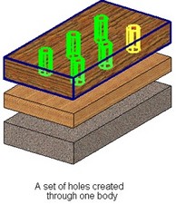
The operation "Hole" creates a set of holes. All holes in a set will be of the same type, size and depth. A set may consist of one or more holes.
For each hole in a set, you specify an attachment point, in the body face where creating the hole. The face hosting the attachment point is called base face of the hole.
Base faces of the holes in one set (that is, holes belonging to the same operation instance) can be same or different, or even belong to different bodies.
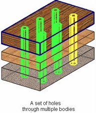
A set of holes on several bodies yields a single multi-body operation. To use each body separately in the future, apply Divide operation after creating the holes.
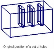
Holes in one set can have different orientation. Hole orientation means orientation of the hole axis in the space and the hole rotation angle about its axis.
The fixing point and orientation of any element in a set can be modified at the operation creation or editing. Any hole can be deleted from a set.
Hole templates
Two mechanisms are used for holes creation: primitives or fragments (templates).
Primitives – a mechanism that creates a special operation to define the shape of the hole. No external objects are used. This mechanism is used to create holes of the following types: square, for fasteners and oblong.
When using a template mechanism, hole creation is realized as an automated process of inserting a special 3D fragment – a hole template.
A template has a set of parameters that define the type and dimensions of a hole created with its help.
Hole templates are stored in the parametric library "Hole Features", among "Utilities". If necessary, the user can add custom elements to this library (see chapter "Custom Elements For Sheet Metal and Holes Libraries").
If inch units are set in the command "ST: Set Document Parameters", on the tab "3D", then the library "Hole Features Inch" is used for creating holes.
The standard library includes hole templates of the following types:
● Holes for check screws (Type 1, 2, 3);
● Threaded;
● Center hole (shape A, B, C, E, F, H, R, T).
To add custom holes to the library, create a template for the new hole type in a separate document, following certain rules, and add it to the respective library ("Hole Features" for those using metric units, "Hole Features Inch" - inches).
Hole attachment point
To specify position of holes being created, specify an attachment point for each hole, one at a time. One hole is associated with one point. The base face of each hole is defined by the system automatically. By default, the axes of the holes are normal to the respective base faces.
Attachment points of the holes can be defined by one of the following 3D elements:
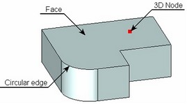
● Face of a body. The specified face becomes the base face of the hole; the hole center will be positioned in the location of the mouse click that selected the face;
● 3D node belonging to one of the body's faces. The face of the node will be set as the base face; the hole center will be at the node;
● Circular edge belonging to one of the body's faces. The face of the circular edge's plane becomes the base; the hole center snaps to the center of the edge's underlying circle.
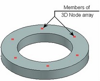
To quickly define a set of holes, you can select an array of 3D nodes for the attachment points. Holes will be automatically created at each 3D node of the array.
The attachment point of any hole in a set can be modified by one of the following means:
1. Define a totally new attachment point (new base face or new attachment 3D element for the hole center);
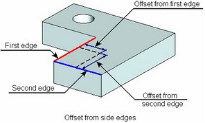
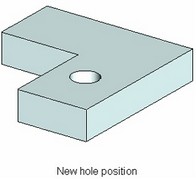
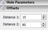
2. Modify the hole position on the current face (maintaining same base face) – by defining offsets of the hole center from the two side edges of the base face. The hole center will be attached to the point on the base face, defined by the specified offsets.
3. Create coaxial hole with automatic adjustment of the hole position on the base face (see the topic "Coaxial holes").
Coaxial holes
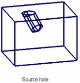
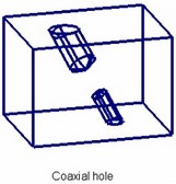
Any hole can be created as coaxial (using the same axis) with an arbitrary cylindrical or conic face. A hole can also be created coaxial with an existing round hole.
The location of the base face should permit creating a coaxial hole. For example, when creating a hole coaxial to another hole, the two holes may not be placed on the same face.
The axis directions of the new hole will coincide with that of the source face.
Hole orientation
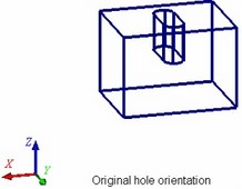
By default, all new created holes are placed by the system in such a way, that the axis of each hole (X-axis of the hole template coordinate system) is directed along the normal to the base face at the attachment point. The orientation of the hole cross section is set by the system arbitrarily. (This is the angle of the hole cross section rotation about the Y-axis of the hole coordinates.)
If necessary, you can modify orientation of each hole in a set separately. A hole's orientation can be modified in one of the two ways:
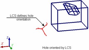
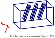
● By auxiliary LCS – a specified LCS is used for defining the direction of the axes of the coordinate system of the hole (existing in its template). The hole is rotated in such a way that its coordinate system axes all get aligned with the direction of the respective axes of the selected LCS;
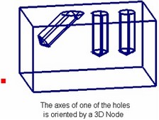
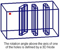
● By 3D nodes. In this case, the hole's orientation and the angle of rotation about its axis are defined separately. You can modify just one of these parameters, for example, only rotation of the hole about the axis, in order to turn a non-round hole about its axis. In this case, the axis itself can be left unchanged (in the system default position).
When using a 3D node for orienting the hole axis, the axis will be directed from the hole attachment point to the 3D node. When specifying rotation of the hole by a 3D node, the Y-axis of the hole coordinate system will be turned so as to point at the selected node.
When orienting by an LCS, you can do this to a whole set of holes simultaneously.
Hole depth
Depth of a set of holes can be specified by a numerical value or calculated automatically, depending on the current mode:
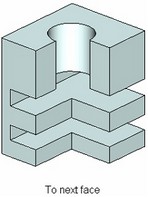
● To next face. Holes are cut up to the intersection with the next face.
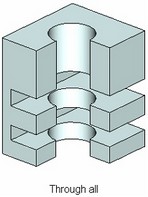
● Through all. Holes are cut throughout the selected body (a set of bodies).
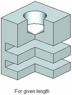
● For given length (depth). The depth of the holes is defined by a numerical value.
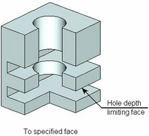
● To specified face. Holes are cut up to the specified face. (The selected face must intersect with the holes being created.)
The holes for check screws and center holes of the shape A, B, C, E, R, T permit the option "For given length" only.
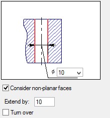
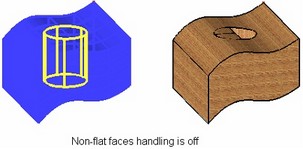
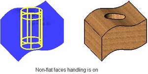
If a hole axis is not perpendicular to the intersected faces of the body, or if faces intersected by a hole are not flat, additional manipulations may be required to get a correct hole entry. In such a case, we recommend using the mode of considering (handling) non-planar faces. In this mode, holes are extended by an allowance amount at either side, and then trimmed by body faces.
Holes through multiple bodies
Holes can be cut through several solid bodies at once. Such sets of holes create multi-body operations.
To use each model body separately in the future, use Divide operation after creating the holes.
You can create coaxial holes in several bodies or fragments and such holes will not be united in one resulting body. Use the Create coaxial holes ![]() option for this purpose.
option for this purpose.
|
<H> |
Create coaxial holes |
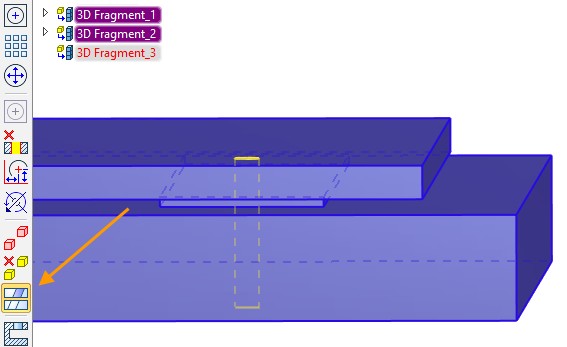
A separate hole will be created for each of the bodies.
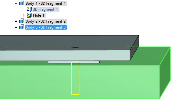
Parameterization is via the common variables. Thus if you specify hole parameters using variables, they will be retained for each of the holes.
Create Holes With Specifies Direction
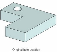
Nodes for the holes are located on the boundary of two or more faces. It is required to create holes on the nodes according to certain direction. Since the system cannot automatically determine the direction, it selects the first appropriate solution. However, the user can independently set the direction by performing the following sequence of actions.
In this example, we will build an array of holes using the nodes created on the edge of the body. The nodes are already created.
Step 1. Select the face for the hole. The face will define the direction for the hole.
Step 2 – Select A: Enter hole center command and select one of the nodes for which holes should be created. The system will construct holes according to the selected face.
Step 3 - Select the rest of the array.
Hole creation
To create standard holes, use the command "3H: Create Hole":
Icon |
Ribbon |
|---|---|
|
3D Model → Modify → Hole |
Keyboard |
Textual Menu |
<3H> |
Operation >Hole |
To create a hole, do the following steps (the order of steps may vary):
1. Select the type and main geometrical parameters of the set of holes to be created;
2. Define attachment points for the holes;
3. Specify the desired hole depth;
4. Modify default axis orientation and rotation angles of the holes (optional);
5. Finish hole creation (use ![]() in the automenu or in the property window).
in the automenu or in the property window).
Selecting type and main geometrical parameters of holes
Select the type of the holes being created in the operation property window. The list of holes contains all elements in the hole utility library (“Hole Features” or “Hole Features Inch”).
Type of a hole can be selected either from the quick access drop-down list or by clicking the corresponding icon. If you select type from the list and it is not presented among icons below, the new icon will replace the last right icon.
Item “Type” in the drop-down list allows you to select element from custom libraries added to selection list.
The content of the selection list is linked with the value of the Standard field and will update accordingly.
You can select holes library using option:
|
<B> |
Library configuration |
More information about configurations can be found in section “Library configuration”.
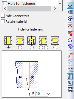
A schematic chart of a hole of the selected type is provided in the lower portion of the property window, with input boxes for all its geometrical parameters. To specify any dimension, just placed the cursor in the respective input box in the chart and type in the desired value (or select one from the list). Variables may be used as values. In this case the value of parameter will be assigned to the nearest value from the appropriate list.
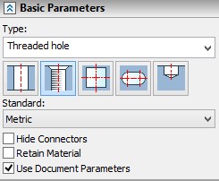
Hide Connectors. Flag allows hiding connectors of created holes.
Retain material. When active, body’s basic material will be applied to the created hole faces. Otherwise, the coating material will be used.
Use Document Parameters. The option is used for holes created using the fragments mechanism. If this option is enabled, the hole uses document parameters, for example, the units. If this option is disabled, the hole will use parameters from the fragment.
|
Reach-through asymmetric hole (e.g. with one side chamfer) may be turned upside-down by its axis direction with option “Turn over”. Often this flag is used for mold-base design. Note that this flag will affect all holes from the set being created. The initially defined type and dimensions of holes can be modified at any time while creating or editing holes (before the confirmation by pressing |
Defining attachment points of holes
Hole attachment points can be defined upon activating the automenu option (the option is active by default upon entering the command):
![]() <A> Enter Hole center
<A> Enter Hole center
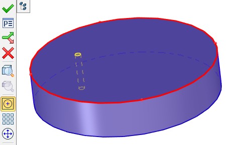
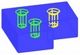
With the option active, simply select the desired face, 3D node or a circular edge on a face in the 3D window. The parent body of the selected element is highlighted, and a wireframe preview of the hole being created is displayed.
After defining the attachment point for the first hole, the option ![]() stays active. This helps creating a set of holes without additional actions. Just keep picking attachment points after selecting the first one. As a result of defining a number of attachment points, a preview of a set of holes is displayed in the 3D scene. The type and geometrical parameters of all elements are the same.
stays active. This helps creating a set of holes without additional actions. Just keep picking attachment points after selecting the first one. As a result of defining a number of attachment points, a preview of a set of holes is displayed in the 3D scene. The type and geometrical parameters of all elements are the same.
Creation of a set of holes from an array of 3D nodes is done with the option:
![]() <M> Add Hole Array
<M> Add Hole Array
Upon activating the option, specify the source array of nodes. You can select an array either in the 3D model tree or directly in the 3D scene by clicking any array element with ![]() .
.
Notice! When you create a holes array, you need to set maximum number of the array elements. If this rule is not met, offset or disappearance of new holes in array can occur after the holes number increase.
Defining hole depth
The desired mode of defining the hole depth is controlled by the following automenu options of the command:
![]() <E> To next face
<E> To next face
![]() <F> Through all
<F> Through all
![]() <J> For given length
<J> For given length
![]() <S> To specified face
<S> To specified face
For some types of holes, certain options may not be available.
Selecting the first two modes does not require any additional actions. The depth of the holes will be determined by the system automatically.
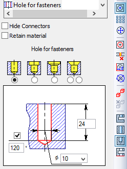
When in the mode ![]() , the hole chart presents additional items for defining the hole depth.
, the hole chart presents additional items for defining the hole depth.
|
|
Appearance of property window in the case of "Hole for fasteners" hole type when defining depth "Through all", "To specified face", "To next face" |
Appearance of property window in the case of "Hole for fasteners" hole type when defining depth "For given length" |
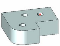
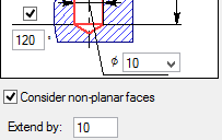
In the last mode (the option ![]() ), you need to additionally select a face in the 3D scene, up to which the holes will be cut. The selected face will be highlighted (by default - red).
), you need to additionally select a face in the 3D scene, up to which the holes will be cut. The selected face will be highlighted (by default - red).
The additional mode of handling non-flat faces is turned on by the flag "Consider non-planar faces" in the lower portion of the operation property window. Setting the flag brings up an additional item in the property window, "Extend by", where the amount of allowance for the hole extension is to be input.
Creating holes through multiple bodies simultaneously
Additional bodies can be selected by the option:
![]() <K> Select additional bodies
<K> Select additional bodies
The bodies can be selected either in the model tree or directly in the 3D scene.
Selection of bodies can be canceled by the option:
![]() <L> Cancel additional bodies selection
<L> Cancel additional bodies selection
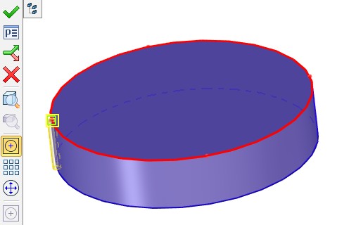
Hole selection for modifying hole position and orientation
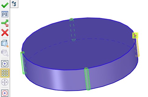
Attachment points and orientation can be modified separately for each hole in a set being created. The hole currently available for editing is highlighted in the 3D scene. The default highlighting color is yellow. Other holes in the set are highlighted green.
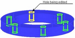
Normally, the last created hole is instantly made available for editing. A different hole in the set can be selected by the option:
![]() <D> Select Hole for edit
<D> Select Hole for edit
Upon activating this option, simply point the mouse at one of the created holes and click ![]() . The selected hole will be highlighted.
. The selected hole will be highlighted.
The selected hole can be deleted by the option:
![]() <X> Delete selected Hole
<X> Delete selected Hole
Modifying hole attachment point
To define a new attachment point from scratch, use the option:
![]() <R> Change Hole position
<R> Change Hole position
Upon calling this option, select a new attachment point for the hole being edited.
A hole position can be modified within the current base face by the option:
![]() <C> Set offsets for Hole
<C> Set offsets for Hole
Upon activating this option, more options will appear in the automenu for selecting edges to offset from and for defining the offset itself:
![]() <D> Select Edge that sets the first offset
<D> Select Edge that sets the first offset
![]() <F> Select Edge that sets the second offset
<F> Select Edge that sets the second offset
![]() <G> Set Hole offset
<G> Set Hole offset
To define offsets, subsequently select two side edges of the base face in the 3D scene by the options ![]() and
and ![]() . The offset values can be defined by simply clicking the mouse at the desired position of the hole center on the face (with the option
. The offset values can be defined by simply clicking the mouse at the desired position of the hole center on the face (with the option ![]() active) or by entering exact numerical offset values in the operation property window. To quit the mode of defining offsets, use the option:
active) or by entering exact numerical offset values in the operation property window. To quit the mode of defining offsets, use the option:
![]() <R> Cancel offset definition for Hole
<R> Cancel offset definition for Hole
Modifying hole orientation. Creating coaxial hole
To reorient a hole, use the following option in the command automenu:
![]() <T> Set Hole direction
<T> Set Hole direction
Upon activating this option, additional options appear in the automenu for defining new orientation of the hole being edited.
A hole can be oriented by an LCS by the option:
![]() <L> Select LCS to define Hole direction
<L> Select LCS to define Hole direction
Upon calling the option, specify the desired LCS. The hole being edited will be oriented by the axes of the selected coordinate system.
A hole axis can be oriented by a 3D node with the help of the option:
![]() <F> Select 3D Node for Hole direction
<F> Select 3D Node for Hole direction
Rotation of a hole about the axis in its current position is done by the option:
![]() <G> Select 3D Node for Hole turn angle
<G> Select 3D Node for Hole turn angle
To quickly reorient all holes in a set, use the option:
![]() <A> Select LCS to define directions of all Holes
<A> Select LCS to define directions of all Holes
A hole coaxial with any cylindrical/conic face is created by the option:
![]() <O> Select hole to create coaxial Hole
<O> Select hole to create coaxial Hole
Upon activating this option, select a face in the 3D scene, whose axis is to be used for creating the coaxial hole.
To undo a defined orientation, use the following options:
![]() <D> Cancel Hole turning
<D> Cancel Hole turning
![]() <Q> Cancel turning for all Holes
<Q> Cancel turning for all Holes
To quit the mode of defining offsets, use the option:
![]() <R> Return from setting Hole direction
<R> Return from setting Hole direction
Library configuration
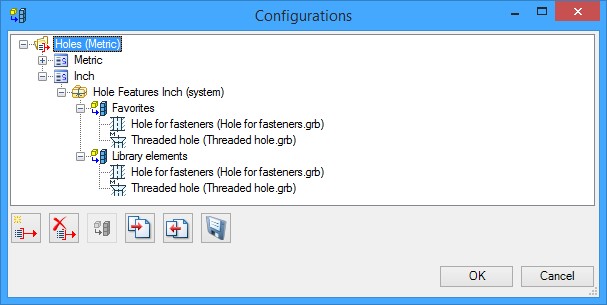
Library Configuration ![]() option displays structure of libraries that are used in the current operation. The option allows to select fragments that will be added to the selection drop-down list. Also it allows to add custom libraries that contain additional fragments.
option displays structure of libraries that are used in the current operation. The option allows to select fragments that will be added to the selection drop-down list. Also it allows to add custom libraries that contain additional fragments.
Configurations window appears when you call the option with the tree that contain the following configurations folders:
![]() Configuration name. Corresponds to the current operation that we configure.
Configuration name. Corresponds to the current operation that we configure.
![]() Standard. Defines subset of libraries that will be linked to this standard.
Standard. Defines subset of libraries that will be linked to this standard.
![]() Library. Contains files of fragments that will be added to the selection list.
Library. Contains files of fragments that will be added to the selection list.
There are “Favorites” and “Library elements” groups inside each library.
All fragment files that exist in the selected library are displayed in its “Library elements” group. The fragments that are included in the quick access drop-down list are displayed in the “Favorites” group.
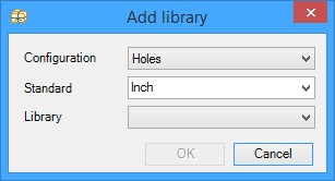
![]() New library. Add Library window appears when you call the option.
New library. Add Library window appears when you call the option.
You need to select configuration, standard and the library that will be added. There are two standards by default: metric and inch. To add a new standard you need to enter its name in the Standard field. Drop-down list in the Library field includes all libraries, that are displayed in the Documents Menu window.
![]() Delete element. Deletes selected configuration, standard or library.
Delete element. Deletes selected configuration, standard or library.
![]() Add/delete fragment as an element by default. Allows to select fragments that will be added to the quick access drop-down list and in the “Favorites” group.
Add/delete fragment as an element by default. Allows to select fragments that will be added to the quick access drop-down list and in the “Favorites” group.
![]() Export library configuration. Allows to export configurations in external *.xml file.
Export library configuration. Allows to export configurations in external *.xml file.
![]() Import library configuration. Allows to import configurations from external *.xml file.
Import library configuration. Allows to import configurations from external *.xml file.
![]() Save changes. Allows to save changes in the configurations.
Save changes. Allows to save changes in the configurations.