Custom Elements For Sheet Metal and Holes Libraries |
  
|
Custom Elements For Sheet Metal and Holes Libraries |
|
This chapter describes the rules of creating custom elements for sheet metal and holes libraries.
The libraries of typical sheet-metal features, "Sheet Metal Features" and "Sheet Metal Features Inch", provided with the system, are used when creating the "Forming Feature" operation. The library elements are 3D models created in a special way. If necessary, the user can append the standard libraries with one's own elements. The first section of this chapter describes the sequence of steps to create such elements.
The standard holes libraries "Hole Features" and "Hole Features Inch" are used in the "Hole" operation. Each element of a hole library is a parametric 3D model, whose geometrical parameters are bound to special reserved variables. Hole libraries can be appended by the user. The second section of this chapter describes methods of creating a 3D model that can be used as a 3D fragment-hole.
Example of Creating a New Sheet Metal Features Library Element
Sheet-metal features library elements are 3D models created by following certain rules. The base of each element's 3D model is the base 3D profile. It is an "external parameter" of the sheet metal feature, similar to external geometrical parameters of adaptive 3D fragments.
Sheet metal feature elements are applied to a part by using the command "SMF: Create Sheet Metal Feature". At that time, a 3D profile is selected on the part, that defines the desired shape of the sheet metal feature. That profile is passed by the command into the 3D model of the sheet metal feature and is used to substitute its base profile. The 3D model of the sheet metal feature element is recalculated according to the new shape of the profile and is inserted in the part's 3D model.
Let's review the creation of a new element using the example of the "Emboss" element included in the standard T-FLEX CAD distribution.
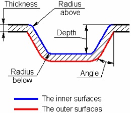
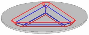
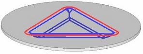
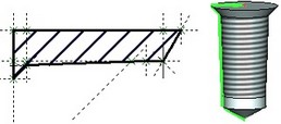
The diagram shows a draft of the elements being created. The inner and outer surfaces of the prospective element are marked by different colors. The dimensions indicate the parameters whose values can be defined by the user. Besides those, the user will be able to select the blending radius of the corners of the original profile. The new sheet metal feature element shall be created as a 3D fragment in the assembly context. Therefore, first you need to create an auxiliary file with the "workpiece" part, to which the forming feature will be applied. This is exactly the document, in which the 3D fragment-forming feature will be created in the assembly context.
An auxiliary file is required only for the process of creating a new sheet metal feature element. You can delete it once the library element creation is complete.
Creating Auxiliary Document
Let's create an auxiliary document to create a sheet metal feature element. With the help of command ![]() you need to create a new 3D model.
you need to create a new 3D model.
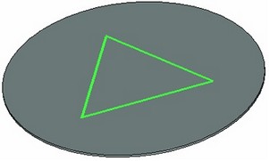
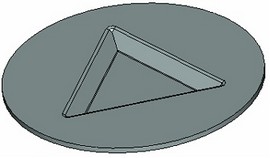
In the created document, let's build the "workpiece" part for the forming feature (by any familiar means). The workpiece should have a simple shape and as few edges and surfaces as possible. The forming feature element file size will depend on how simple the workpiece is, and so will the time to open and recalculate the element. Best of all is to make it round and flat. Let's create the 3D profile on the top faces of the workpiece, that will be the base profile of the forming feature element. The profile should also be made as simple as possible. In this example, let's create a triangular profile.
Save the file under the name "Part for emboss". Now we can proceed with creation of the forming feature element itself.
Creating the 3D Model of a Sheet Metal Forming Feature Element
1. Create a new 3D fragment by calling the command "FM: Create Fragment in Assembly" ("File|Fragment|Create") and specify an arbitrary name for the prospective element, for example, "Emboss new". After clicking [ОК], the assembly context mode activates automatically (the source body will become transparent).
Make sure that the associative snapping mode is On. To do this, click the right mouse button on an empty space in the 3D window and select the context menu item "Snap Modes".
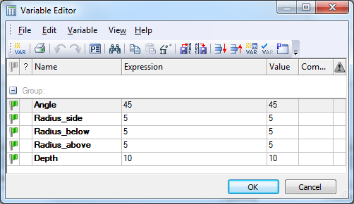
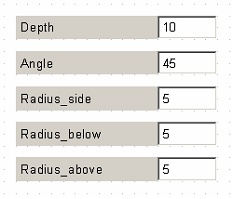
2. In the variable editor, create required variables that will define the element parameters: "Depth", "Angle", "Radius_side", "Radius_below", "Radius_above". All variables must be external.
3. To correctly create the forming feature, you need to know the thickness of the source workpiece. To have this thickness defined automatically, you can use the top and bottom faces of the workpiece. Call the command "Parameters|Measure", select the option "Measure relation between two elements". Specify the top and bottom faces of the workpiece, and click ![]() . In the list of relations, select "Distance", and then create the "Thickness" variable based on it. The value of the created variable will be equal to the distance between the selected faces (the thickness of the source body).
. In the list of relations, select "Distance", and then create the "Thickness" variable based on it. The value of the created variable will be equal to the distance between the selected faces (the thickness of the source body).
4. Extrude (the "3X: Create Extrusion" command) the triangular profile lying on the top face of the source body. When creating the extrusion, the top face shall be selected for the direction; click the The extrusion we have created ("Extrusion_1") will be used to obtain the inner surface of the forming feature. When creating an ordinary model, it is possible to skip using additional blending options for the extrusion and instead use common blend operations. However, in the present case that is not an option, since the model must correctly recalculate with any admissible 3D profile. If, for example, we would change the number of joint points of the top 3D profile in the "Part for emboss" file, then the 3D model in the "Emboss new" file would still recalculate correctly. If using an ordinary blend, then this may not work if it fails to account for the increased number of profile edges. |
|
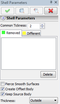
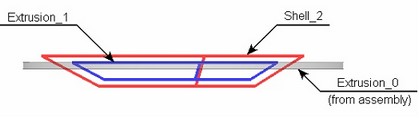
5. To obtain the external surface, we will use the "Shell" operation. Call the command "3SH: Create Shell", select the option "Select a body" and specify the extrusion created at the previous step. Enter the name of the "Thickness" variable in the "Common Thickness" field. Set the shell parameters as shown on the figure on the right: the "Create offset body" and "Keep source body" flags shall be made active. The created body will be named "Shell_2". |
|
6. By now we created the inner portion of the "Emboss new" prospective element – "Extrusion_1", its outer portion – "Shell_2" and the source workpiece – "Extrusion_0 (from assembly)". But "Shell_2" comes out above the source body. This outcoming portion needs to be deleted.
To cut the extra portion, we will use the "3CU: Cut By Section" operation. Select the top face of the source workpiece body as the cutting plane. The resulting body will be called "Cut operation_3".
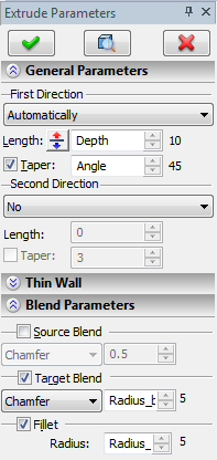
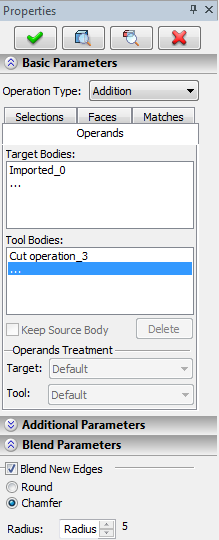
7. It is now possible to add together "Cut operation_3" and the source workpiece (the latter being no longer needed) using the Boolean operation (the "3B: Create Boolean" command). In the Boolean operation properties set the flags "Blend New Edges" and "Chamfer". The "Radius" parameter value shall be defined by the following expression: Radius_above-Thickness>=0? Radius_above-Thickness:0. When creating the Boolean operation, chamfers will be created on new edges. The chamfer offsets shall be less than the "Radius_above" defined by the user, by the "Thickness" amount, and cannot be less than zero. This requirement conditions the above-written expression. 8. What is left now is to generate the inner surface of the "Emboss new" element. To do this, we shall use a Boolean operation again. We will subtract "Extrusion_1" from the "Boolean_4" body obtained at the previous step. Just like in the previous step, the option of chamfer creation on new edges shall be enabled in the Boolean operation properties. The chamfer size shall be defined by the "Radius_above" variable. |
|
At this point, the new forming feature model element can be assumed completed. Next, right-click ![]() on an empty space in the 3D window and select the context menu item "Save Fragment and return". The "Emboss new" file, which contains the created 3D fragment, will become a new element in the sheet metal features library.
on an empty space in the 3D window and select the context menu item "Save Fragment and return". The "Emboss new" file, which contains the created 3D fragment, will become a new element in the sheet metal features library.
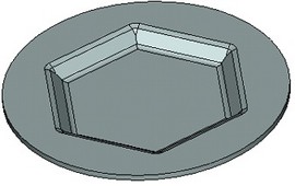
What to do with the obtained sheet metal forming feature element will be described a bit later. For now, let's verify the function of the created forming feature element. Upon finishing working in the assembly context, the "Part for emboss" file will open again. You do not have to save it – we shall not need it anymore. But, before the file is closed, change the number of segments in the source profile on the "workpiece" of the part – the forming feature shall adjust accordingly.
Creating a Dialog for New Library Element
Besides the 3D model proper, a new sheet-metal library element requires creation of a dialog to input parameters of the given forming feature element (which is the external fragment element parameters). This dialog will be coming up in the command "SMF: Create Sheet Metal Feature" when inserting our forming feature element.
To create the dialog, open the file "Emboss new". Add a new 2D page to it to hold control elements (the "TR: Create Control" command). On this page, position the elements of the "Static Text" type with the appropriate parameter names and the value input fields ("Edit Box" elements) for all external variables of the created fragment using the "TR: Create Control" command. As a result, you will get a simple dialog that will serve to help the user defining parameters of the forming feature being created. If desired, a more complex dialog can be created, by introducing in it a schematic image of the element as in standard sheet metal library element dialogs.
The forming feature dialog is automatically scaled in the "SMF: Create Sheet Metal Feature" command property window so as to have the font size in it matching the Windows font size. Therefore, when creating a dialog, we recommend you not to change the font size set by default for the dialog page (it is set to be close to a standard Windows font). This will help avoid distortions when displaying the dialog.
Besides that, do not create too wide dialogs that do not fit within the standard property window.
After creating the dialog, save the file again.
Defining Limitations on the Source 3D Profile Type
Limitations can be imposed on the type of a 3D profile that will be used for creating the new forming feature element in the "SMF: Create Sheet Metal Feature" command. To impose limitations, you need to create two external variables named "contour_type" and "profile_type". The values assigned to those variables will define the 3D profile types allowed for the given forming feature element:
profile_type: defines the geometrical appearance of the 3D profile contour |
contour_type: defines the nesting of the 3D profile contour |
0 - any 1 - closed 2 - open 3 - line segment 4 - from polylines |
0 - any 1 – simple only (no nested contours and no multiple contours) 2 - no nested contours |
When these variables are created, then, upon an attempt to select a 3D profile of an inappropriate type in the forming feature creation command, the system will output an appropriate warning in the Diagnostics window. As a result, the profile will not get selected. On the other hand, if the variables were not created in the forming feature fragment, then, when applying it, any 3D profile types will be allowed for selection. The fact that an incorrect profile was selected will then only be hinted by the errors occurring when recalculating such a forming feature.
In our example, the "profile_type" variable must be equal to 1, and the "contour_type" variable must be equal 0.
Adding a Created Fragment to the Sheet Metal Features Library
To use a created element in the "SMF: Create Sheet Metal Feature" command, you need to copy the "Emboss new" file into the folder "... T-FLEX Parametric CAD 14\Libraries\System\Sheet Metal Features". After that, when calling the forming feature creation command, the created element will show up in the list.

Element Name and Icon
Our new forming feature element will be referred to in the "SMF: Create Sheet Metal Feature" command by its filename and the standard icon of a T-FLEX CAD document. If desired, it is possible to define for it another, more intuitive and complete, name. To do that, call the "PS: Show Model Properties" command in the element file (in our example that's "Emboss new"), and fill in the "Title" field on the "Summary" tab.
Icon may be changed using command IC: Create/Edit document icon.
More information about icons creation can be found in “Preview-slide” chapter.
Example of Creating a New Holes Library Fragment
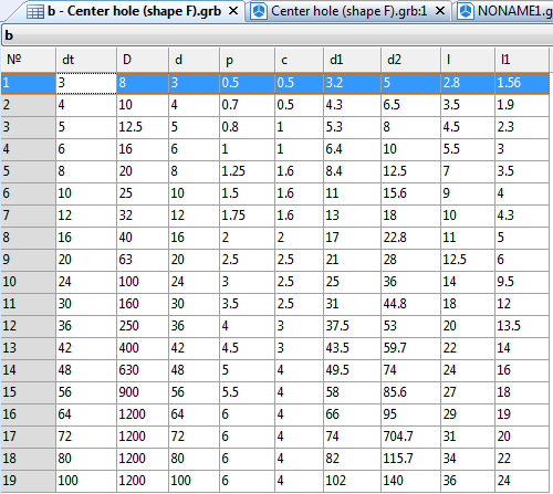
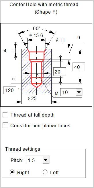
Let's review another example of creating a new hole fragment. Open a standard hole – "Center Hole (shape F)":
1. Since there are different implementation versions of the hole, an internal database was created within the fragment document, that contains standard dimension sets.
2. Special external variables were created in the fragment document that are required for correct handling of the fragment in the command "3H: Create Hole":
●IsThrough – this is the variable that defines the hole type (0 – blind, 1 – through).
The 3D model of any hole fragment shall be created in such a way as to have the hole type (blind, through) change depending on this variable value. The variable value will be determined by the state of the option in the command "3H: Create Hole" when inserting the hole. This external variable must necessarily be present in the hole fragment.
●length – this is the variable responsible for the hole depth (when creating a fragment, this variable value can be arbitrary).
When applying a fragment, this variable value will be determined by the system (for a through hole) or by the user in the fragment's external variables dialog (for a blind hole).
You do not have to create this variable (or make it external), if the hole being created can only be blind and its depth cannot be arbitrary, but is rather determined by the standards. In such a case, the depth is uniquely determined by other hole parameters (for example, the diameter, as found in the holes for the positioning screw tips). When applying a hole without the "length" external variable, the hole type selection options will be inaccessible in the "3H: Create Hole" command automenu.
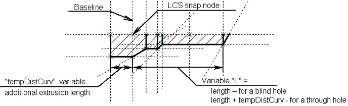
Other necessary variables can be created and named by the user as desired. For example, in the described hole fragment, an additional external variable "IsThrough" is created. Depending on its value, the hole length can be increased by the amount defined by another external variable, "tempDistCurv". This is necessary in the case when the hole is applied on a curved face (convex or concave) or is directed at an angle to a flat face. When the "IsThrough" variable value is equal 0 – no length extension is required, 1 – the length needs to be extended. A blind hole will be extended by this amount on one side, a through one - on both sides.
3. The 3D profile of the hole is created based on 2D constructions on a workplane. 2D constructions are made in such a way as to describe all possibilities for creating a given hole (the change of the hole type is defined by the values of the above-described variables).
4. A rotation operation is created based on the 3D profile.
When creating a hole it is also possible to use the "Extrusion" command. An example is a square hole in the standard library. A general rule while creating any hole fragment is to create only a single body in it. If a hole has several versions, its shape should be possible to change using construction lines.
5. Since the considered hole is threaded, there is a thread applied to the cylindrical face (the "3AT: Create Thread" command). The cylindrical face diameter corresponds to the inner thread diameter. The thread parameters (type, diameter, pitch, direction) are bound to variables. To make sure that the thread in the hole appears correctly on a projection, the "Thread" operation parameters include the "Side/Inner" property.
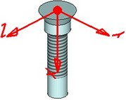
6. To snap a hole when using it in the "3H: Create Hole" command, a local coordinate system is created. An LCS for snapping any hole is created by the following rules: the coordinate system origin point must be on the hole axis, the X-axis must be directed inward of the hole along its axis. In the coordinate system parameters, have the "Use for Fragment Fixing" flag set.
7. To manage hole parameters, a dialog of control elements is created.
8. The file of the described hole fragment is stored in the folder "…T-FLEX Parametric CAD 14\ Libraries\System\Hole Features". This is how it is made accessible in the list of holes in the "3H: Create Hole" command.
The mentioned folder is for the metric library of holes. Save inch-base hole files in the folder "…T-FLEX Parametric CAD 14\Libraries\System\Hole Features Inch".
9. Additionally, the full name of this hole is specified among the properties of the described fragment file. Besides that, the file of the whole icon is created in the same folder, that contains the images in two sizes (16x16 and 32x32). The icon file name matches the name of the hole fragment file. The hole name and its icon will be displayed in the list within the "3H: Create Hole" command.
The icon creation and the hole name definition are optional. Nevertheless, those help make the hole handling more intuitive in the "3H: Create Hole" command.