Shell |
  
|
Shell |
|
Main concepts
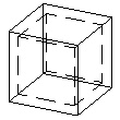
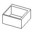
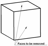
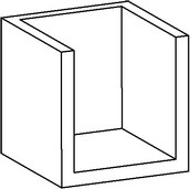
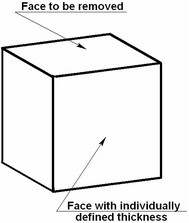
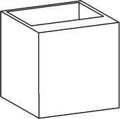
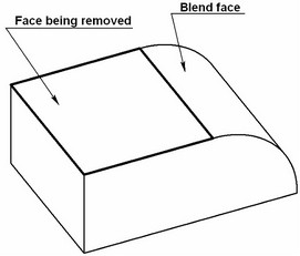
The operation "Shell" allows creating offset bodies and shells based on solid bodies. A shell is a hollow, thin-wall body with walls of the specified thickness. When creating a shell, some of the source solid body's faces can be removed.
The operation "Shell" is based on the following principle: an offset surface is created for each face of the source sheet or solid body, at the specified offset distance. Depending on the user preference, the offset can be outwards or inwards of the surface of the processed body (codirectional or counter-directional to the normal). The offset surfaces can be used as a self-contained result – for creating offset bodies. Alternatively, offsets can be used for making a shell by confining a portion of the inner volume of the source solid body.
Shell creation
The command "3SH:Create Shell/Offset Body" is called by one of the following means:
Icon |
Ribbon |
|---|---|
|
3D Model → Modify → Shell |
Keyboard |
Textual Menu |
<3SH> |
Operation > Shell |
To create a shell, do the following set of steps:
1. Select a face to remove or a whole solid body.
2. Select a face whose wall thickness is to be defined separately (if desired).
3. Define parameters. (Optional action.)
4. Finish input.
To create an offset body, do the following set of steps:
1. Select the source sheet or solid body.
2. Activate the mode of creating offset body.
3. Define parameters. (Optional action.)
4. Finish input
Selection of a face or body to remove
To create a solid shell with one or multiple face removal, use the option:
![]() <R> Select Face to be removed
<R> Select Face to be removed
This option activates by default upon calling the command. It allows selecting a face or a set of faces to be removed when creating the shell. The parent body of the first selected face to be removed also gets selected. The body itself is not highlighted, while the selected face is highlighted in a specific color.
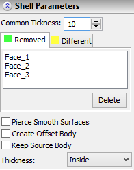
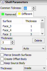
The faces selected for removal are added to the list in the provided pane in the property window on the tab [Removed]. Placing cursor in the list pane in the property window activates the option for selecting faces to remove. The thickness of other walls of the shell being created is defined in the input box "Common Thickness" of the property window. The default value is 1. This means the walls of the faces left in the body will be 1 mm thick (the measurement units depend on the document settings). |
|
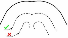
Thickening the walls of the shell can be done either outwards or inwards of the source body. This is controlled by a special additional parameter in the property window ![]() .
.
The wall thickness can be positive or negative. Use of negative values results in shell thickening in the opposite direction.
To create a shell without removing any faces, upon entering the command switch to the automenu option:
![]() <O> Select Solid
<O> Select Solid
This option allows selecting a solid body to create a hollow body with the specified wall thickness.
Selection of faces with individually defined wall thickness
To define the wall thickness individually for one or several faces, select such faces with the help of the automenu option:
![]() <T> Select Face with different wall thickness
<T> Select Face with different wall thickness
This option becomes accessible when the whole body or a face to be removed is already selected. The selected faces are referred to as "Different" and are added to a separate list on the tab [Different] in the property window. The thickness of each such face can be defined in the input box "Thickness" after selecting one or several faces in the list.
The option:
![]() <K> Cancel selection of Faces by pointing to them
<K> Cancel selection of Faces by pointing to them
is provided for unselecting faces to be removed or faces with individually defined thickness. To cancel a selection, point the mouse at a selected face and click ![]() . Faces can also be unselected by manipulating the respective list in the property window. For this purpose, the graphic button [Delete] is provided with each list.
. Faces can also be unselected by manipulating the respective list in the property window. For this purpose, the graphic button [Delete] is provided with each list.
All faces can be unselected at once by the option:
![]() <F> Cancel selection of all Faces
<F> Cancel selection of all Faces
You can confirm the operation creation as soon as the option becomes accessible in the automenu:
![]() <Y> Finish input
<Y> Finish input
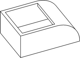
As a result, a shell body will be displayed in the 3D window.
Additional operation parameters
Additional operation parameters can be set in the property window, using the following switches:
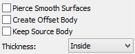
Pierce smooth surfaces. Setting this parameter allows creating a shell in the cases when the removed face is tangent to adjoining non-flat faces, such as those created by blending (radial fillet).
Create offset body. Setting this flag activates the mode of creating offset (rather than hollow) body. The faces of such body are offset from those of the source body by the specified amount. This mode can be useful for creating workpieces with allowance for machining.
Only sheet bodies can be used for creating offset bodies in the command "Shell".
Keep source solid. This option allows keeping the source solid body in the scene together with the result. This can be useful when you need to have two models at once, like a workpiece with allowance and an original part.
Troubleshooting
When creating "Shell" operation, the system may fail to calculate the result in some cases. A reason for a failure could be particulars of the source body geometry. Let's review most typical situations:
1. Degenerate faces. When creating an offset, some faces may disappear. The system may handle some of the cases. However, if there are too many such faces, or several adjacent faces disappear, the system outputs an error.
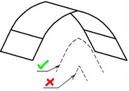
2. Offset faces do not intersect. Upon creating offset faces, the system constructs intersection lines between adjacent faces for generating the resulting body. In some cases, two adjacent offset faces may not intersect.