Photorealistic Images |
  
|
Photorealistic Images |
|
General concepts
Ray tracing of the 3D scene is a special way of rendering the scene that accounts for shadows cast by the objects, as well as for such phenomena as light reflection and refraction.
There are three different mechanisms of photorealistic images generation. First of them uses POV-Ray application, the second uses integrated NVIDIA OptiX technology, the third uses Embree – ray tracing kernel developed by Intel.
Selection and settings of image quality
It is rather unlikely that a satisfactory photorealistic image will be created on the first try. Usually, several test photo renderings are required that help adjusting the camera position, brightness and position of the light sources, and checking the animation correctness. After that, the final rendering is run.
However, photo rendering could take unspecified time, depending on the scene complexity and the parameters defining the image quality. Understanding these parameters helps avoiding excessive time spending on test renderings, on one hand, and helps achieving higher quality of the final image, on the other hand.
There are various parameters for adjusting the quality of the resulting ray-traced image.
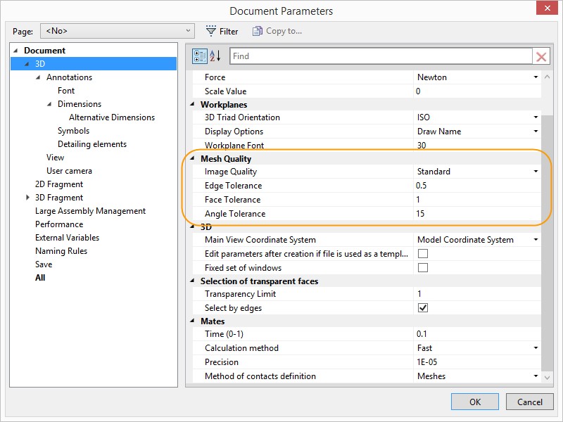
Mesh density. This parameter is defined in the document parameters (the command "ST: Set Document Parameters"), and, besides the photo rendering, affects the quality of rendering objects in the 3D window.
Photorealistic View
The second mechanism for generation of the photorealistic images uses NVIDEA OptiX technology. It is used for creating of high quality images based on lighting and material properties such as transparency, refractive index, surface properties, etc.
The mechanism allows obtaining photorealistic images directly from T-FLEX CAD environment, providing convenient interface of 3D scene parameters management, control over the quality of result and possibility to print result or save it into a file.
With this mechanism, photorealistic image can be generated not only from three-dimensional solid models, but also from imported 3D models.
The NVIDIA OptiX technology is used for creation of photorealistic videos when you record 3D model exploded view animation in command “3VX: Exploded View”.
The third mechanism for generation of the photorealistic images uses Embree – ray tracing kernel developed by Intel.
Embree uses CPU for its calculations and provides high performance and image quality.
User interface for NVIDIA OptiX is similar to the Embree. They will be described together in the following chapters
Command of Photorealistic View
To activate the command use:
Icon |
Ribbon |
|---|---|
|
Tools → Title block → Photorealistic view → Photorealistic view (GPU NVIDIA) |
Keyboard |
Textual Menu |
<3RV> |
Tools > Photorealistic view (GPU NVIDIA) |
Icon |
Ribbon |
|---|---|
|
Tools → Title block → Photorealistic view → Photorealistic view (CPU Intel) |
Keyboard |
Textual Menu |
|
Tools > Photorealistic view (CPU Intel) |
After activation new window with generated image appears.
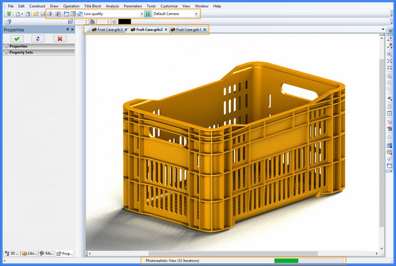
Quality of the generated image depends on the number of iterations. The iteration is evaluation of image pixels color. The evaluation process depends on image size, mesh quality and number of objects.
The iteration number is displayed in the lower part of the window.
![]()
Process of the image generation can take from several minutes to several hours according to your computer power, model complexity and image quality.
Options for the operation are displayed on toolbar.
![]()
![]() Print image. Allows to print generated image.
Print image. Allows to print generated image.
![]() Save image. Allows to save generated image in *.bmp, *.jpg, *gif, *tiff, *tif, *.png, *.tga formats. You can set the file name and specify folder.
Save image. Allows to save generated image in *.bmp, *.jpg, *gif, *tiff, *tif, *.png, *.tga formats. You can set the file name and specify folder.
![]() View parameters. Allows defining the image generation parameters. More information about it can be found below.
View parameters. Allows defining the image generation parameters. More information about it can be found below.
![]() Fix generation parameters. Allows fixing the image view and scale. Model rotation becomes unavailable.
Fix generation parameters. Allows fixing the image view and scale. Model rotation becomes unavailable.
![]() Update generation of photorealistic view. Restarts photorealistic view generation. All current results are cancelled.
Update generation of photorealistic view. Restarts photorealistic view generation. All current results are cancelled.
![]() Pause photorealistic view generation. Allows to pause generation of the image. This option stops calculations and releases computer resources.
Pause photorealistic view generation. Allows to pause generation of the image. This option stops calculations and releases computer resources.
Image quality. You can set one of four kinds of quality from the drop-down list.
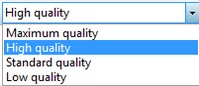
The low and standard qualities are used for rough drafts of images. When one of them is set, the minimum quantity of iterations for generation of the image with certain level of “noise” is evaluated by the system.
To generate the most realistic images you need to choose high or maximum quality. When the quality set to maximum, the number of iterations is not limited.
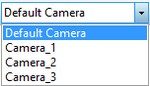
Select of current active camera. Allows to select one of the cameras existing in scene. Image will be generated according to the camera location.
![]()
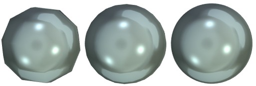
An important role in the photorealistic image creation plays “Mesh Quality” configuration. You can change it with the drop-down list on the “3D” tab in the “ST: Set Document Parameters” window.
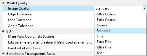
The higher the quality the higher is the density of the mesh. To create the most realistic images, it is recommended to set “Fine” or higher quality.
This configuration is especially important for models with rounded faces.
Difference between images with different quality.
|
||
Ultra Coarse |
Standard |
Ultra Fine |
Generation of photorealistic images requires high computer characteristics. More information about requirements can be found on our website or in the “Getting started” chapter.
The image generation can be paused anytime. Its result can be saved to disk with option ![]() or printed with option
or printed with option ![]() .
.
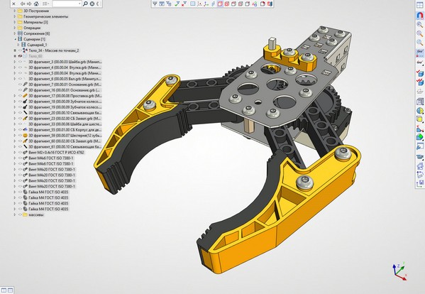
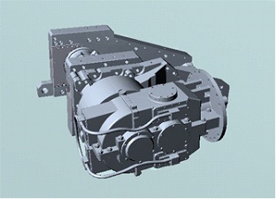
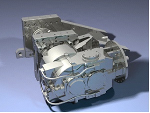
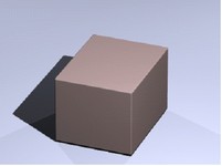
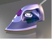
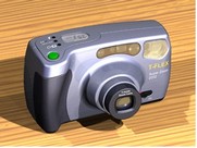
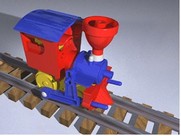
Source model
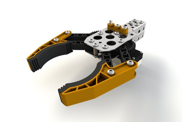
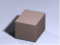
Photorealistic image
Examples of photorealistic image generation can be found in library “Examples/Additional resources/Materials and photorealistic view.
The photorealistic image and 3D model windows can be displayed simultaneously. For this purpose use command “WO:New Window”.
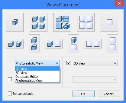
In the dialog window select “Photorealistic View” from the drop-down list. You can set convenient windows placement with the help of four drop-down lists.
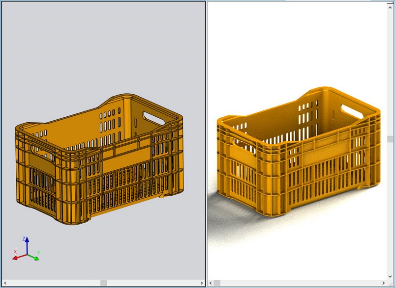
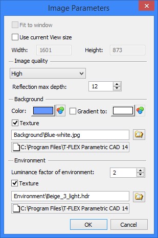
Image Parameters
Fit to window. The option is enabled only when the flag “Use current view size” is set. When the option is active, image of the current size is fully displayed. Use current view size. When active, the option allows to set the generated image size. After activation, option “Fix generation parameters” Size of the image is specified in pixels. The image of specified size will be generated completely, even if it does not fit the window. To generate images of the highest quality it is recommended to set the largest current view size. Image quality. The option duplicates the drop-down list of settings from the toolbar. The only difference is the possibility to set the number of iterations manualy. You need to select user quality and specify the number of iterations. Reflection max depth. The option is important for generation of refractions and reflections. All texture parameters are similar to the standard parameters of 3D view. More information about them can be found in chapter “Working with the 3D view window”. Luminance factor of environment. Allows to set luminance by adjusting the amount of light coming to objects. |
|
Photorealistic Images Examples
NVIDIA Optix:
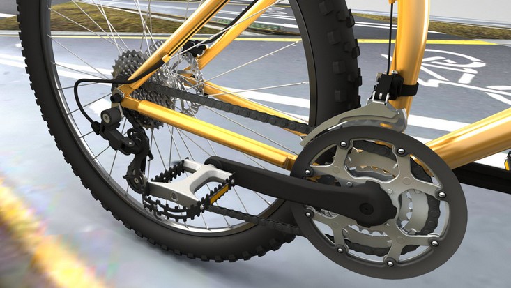
Embree:
Ray Tracing
This mechanism uses POV-Ray, a ray tracing program which generates images from a text-based scene description exported from T-FLEX CAD. POV-Ray installation is included in T-FLEX CAD installation package or can be downloaded from appropriate web site.
|
|
Note that the POV-Ray application requires separate installation. To install it, select the file "povwin36.exe" on the distribution CD, in the folder "POV-Ray". POV-Ray installation runs in English. The users who do not know the English language are advised to follow all pre-selected items (such buttons as [Next], [Yes] or [I Agree]) in the subsequently coming windows of the wizard.
When creating a ray-traced image, the 3D scene is exported into POV format, using the settings of the current 3D window. Next, the POV-Ray application is automatically launched for generating the photorendering. Once generated, the resulting image can be viewed in the View window and, if desired, saved in a file.
POV-Ray processing runs parallel to other systems; therefore, you can continue working with T-FLEX CAD after launching this application. However, depending on the complexity of the image being generated, POV-Ray may consume more resources, and so T-FLEX CAD operation could be delayed.
The greater this parameter is, the longer time it takes for exporting the scene by POV, the more RAM is used by POV-Ray and the longer POV-Ray runs the preprocessing of the scene before the rendering (Parsing). Due to this fact, we recommend decreasing the mesh density when running a test rendering, sometimes even up to the minimum setting. When running the final rendering, best is to use the maximum mesh density.
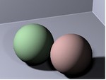
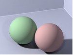
Light source parameters. When creating a photorealistic image by using conventional light sources, the objects cast well-defined shadows because the light sources are infinitely small. In the reality, this happens very seldom; therefore, shadows are often blurred. The use of the diffused light sources allows making shadows smoother and enhances the image quality and realism. The diffused light sources use multiple concentrated light sources offset from each other, instead of one such light source. The more those are offset, the less sharp will be the shadow. The more concentrated light sources are included in a diffused light source, the more the shadow is blurred and the longer time it takes for the rendering.
|
Diffused light |
A diffused light source in POV-Ray is made of multiple concentrated light sources. These light sources are placed in a rectangular array oriented in a certain way with respect to the specified center. The number of light sources along each of the rectangle's sides can be different. To make a light source created in T-FLEX CAD a diffused light source in POV- Ray, enter the following in the "POV Instructions" input box for the light source properties:
area_light <0.035, 0, 0>, <0, 0.035, 0.035>, 5, 5 adaptive 1 jitter
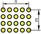
Above, the coordinates of the opposite corners of the rectangle are entered in the angle brackets with respect to the origin point (the point where the diffused light source is positioned). "5, 5" - is the number of light sources in each direction. In this way, the total number of the concentrated light sources is equal to 5x5=25. "adaptive 1 jitter" - are the additional parameters directing optimization of shadow calculation.
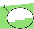
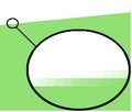
Antialiasing. In conventional rendering, the phenomena of jagging and dashing of thin lines could be encountered. Smoothing by additional calculations may reduce the negative impact of such phenomena.
Jagged edges |
Antialiasing is on |
Antialiasing involves increasing the resolution when visualizing some parts of the scene. This slows down the scene rendering. Therefore, avoid using antialiasing in test renderings. However, antialiasing is preferable in the final rendering.
Radiosity. In conventional renderings, only the direct light is accounted for, that illuminates only the objects directly lightened by the light source. However, in the real world, the light originates not only from the sources. It is also reflected from the objects illuminated by the direct light. POV-Ray provides an option of turning on the method of calculating radiosity, that in certain cases enhances the image realism.
Conventional light |
Radiosity |
Due to bulky additional calculations, use of radiosity mechanism may cause significant slowdown of rendering. Therefore, use low resolution when including radiosity in test renderings.
To turn on the radiosity mechanism, enter the following expression in the "Include statements" input box of the "Ray Tracing Options" window:
global_settings {
radiosity { count 500 minimum_reuse 0.018 brightness 0.8}}
Refer to the POV-Ray application manual for the meaning of the quoted instructions, as well as for additional information regarding the radiosity mechanism.
Image resolution. This parameter noticeably affects the time used for rendering. With the image quality defined, the speed of rendering is directly proportional to the size of the resulting image. You can restrict test renderings to small resolution, for example, 320*240.
Command operation
To create a ray-traced image, use the command "3VY: Ray Tracing". This command will be available if the 3D window is active. Before calling the command, set the 3D scene in the desired orientation, apply the desired materials to the operations, place light sources (one can use the light sources on the camera). Prefer the perspective projection when creating a ray-traced image.
The command is called as follows:
Icon |
Ribbon |
|---|---|
|
Tools → Title block → Photorealistic view → Ray Tracing (POV-Ray) |
Keyboard |
Textual Menu |
<3VY > |
Tools > Ray Tracing (POV-Ray) |
T-FLEX CAD saves the information about the location of POV-Ray application and checks its availability upon each call to this application. The first time POV-Ray is called, as well as in the cases, when the system cannot find this application, T-FLEX CAD requests the path to the application. In such a case, a dialog box is displayed that allows defining the path to the POV-Ray application. Normally, the path to this application is: "Program Files\POV-Ray\bin". If this folder is missing, the application may not be installed.
Upon calling the command, the following dialog box will be displayed.
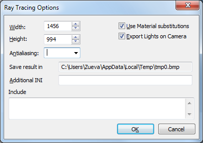
Width and Height. These define the width and height of the ray-traced image being created, in pixels. The default size is that of the current 3D window.
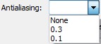
Antialiasing. Provides smooth color transition in the generated image. The value of this parameter must be greater than 0.
The smaller is this value, the softer will appear the transition from one color to another; however, the rendering (image generation) will take more time in this case. The value of this parameter can be selected from the list or specified manually.
Use Material substitutions. POV-Ray uses a special language for describing the 3D scene. It allows specifying a large variety of properties for material surfaces and insides. Due to this, T-FLEX CAD uses special instructions for materials, determining, how a material would appear when visualized in POV-Ray (the command "3MT: Edited Materials", the button [POV Material]). When the "Use Material substitutions" flag is set, those instructions are passed to POV-Ray. All materials included in the system distribution possess special instructions for POV-Ray. Besides the materials, the light sources and additional instructions for light sources will also be exported in POV (see "Light source parameters", the item "POV Instructions").
If the "Use Material substitutions" flag is off, then the instructions will be passed on to POV-Ray, that are automatically generated by T-FLEX CAD based on such material properties as color and specularity.
Export Light on Camera. By default, one or more light sources are attached to a camera in the 3D window. These light sources have specified orientation with respect to the camera and move together with it (see the manual on "3D View Parameters"). If the flag "Export Light on Camera" is on, those light sources are passed to POV-Ray.
Save result in. This item displays the path to the temporarily created output file that used by POV-Ray for setting the resulting image in the bmp format, and by T-FLEX CAD for reading it. Therefore, if T-FLEX CAD is closed before the result is created, the image in this file can be viewed later, using any other program for viewing images.
All temporary files created during the image generation are stored in the folder pointed at by the system variable TEMP. Upon completing the image, all files except the output one are deleted. The output file itself will remain in this folder up until creation of another ray tracing.
Information for advanced users of POV-Ray
Additional INI file: When the POV-Ray application is started, a file is created with the extension ini, recording the exported settings. If necessary, different settings can be specified in this file, even redefining those generated in T-FLEX CAD. Should this be the case, enter the desired filename in this input box of the dialog.
Include statements: You can type expressions in this pane, in the POV format, that will be inserted in the exported file.
Clarification: When launching the command, a file in the POV format is created that has the following structure:
<generated variables>
<included expressions>
<exported 3D scene>.
Generated variables.
The following variables are included in the exported file:
fAspectRatio – Width / height screen ratio. When redefining the Width and Height settings in the additional INI file, you need to also redefine this variable by using <included expressions>.
vSceneMin and vSceneMax – the corners of the box outlining the 3D scene in the 3D space.
vSceneCenter – the center of the box.
fSceneSize – the length of the box's diagonal.
vCameraPos – the camera's position.
vCamera2Scene – the vector from vCameraPos to the box center.
fCamera2Scene – the vCamera2Scene vector length.
cBackColor – the background color.
These variables can be redefined or used in <included statements>. Example:
#declare cBackColor <0.1, 0.1, 0.1>
fog {
fog_type 2
distance fCamera2Scene / 2
rgb <0, 0, 1>
fog_offset vSceneMin . z
fog_alt (vSceneMax . z - vSceneMin . z) / 4
up <0, 0, 1>
}
redefines the background color and sets blue fog that depends on the orientation and size of the 3D scene.
Upon defining all necessary parameters for creating a ray tracing, press the button [OK]. Sometimes, when running POV-Ray, the "About POV-Ray(tm) for Windows" dialog box may pop up. In such a case, to run the application, simply press the button [OK].
When creating an animation with photo rendering turned on by using the command "AN: Animate Model", you are advised to wait until the first frame visualization starts in POV-Ray, to make sure that the "About POV-Ray(tm) for Windows" window does not pop up and does not interfere with the animation creation.
Once POV-Ray is launched, control returns to T-FLEX CAD so that you can continue working with it. Upon completing the image generation or in the case of its termination, a message is displayed on the screen:
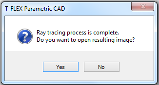
To view the resulting image, press the button [Yes]. As a result, the view window opens allowing to save the image in a file. If viewing and saving the resulting image is not necessary, press the button [No]. In this case, the resulting ray tracing will remain in the system folder TEMP (until the creation of another ray tracing).
POV-Ray can be started again before completing an image generation (the number of starts is not limited). In such a case, T-FLEX CAD exports data in POV, and then, once the process of the previous image generation finishes, will launch another POV-Ray application. This creates a queue of image generation tasks, with a new task launched upon completing the previous one.
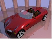
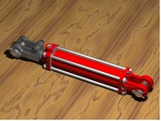
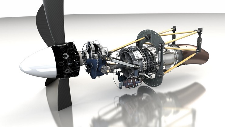
Examples of ray-traced images of T-FLEX CAD models
|
|
|
|
|
|
Photorendering Prototypes
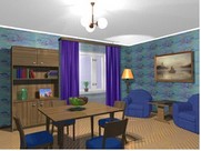
The standard distribution includes the prototypes designed specifically for quick creation of ray tracings. To create documents based on such prototypes, call the command “FP: Create New Document Based on Prototype”, and on the tab “Photorendering” select one of the two prototypes: “Room” or “Flying around object”.
Each of these prototypes has several predefined light sources, a camera and a coordinate system for fixing a 3D fragment. The placement of these elements can be modified as desired by moving the respective elements in the drawing window. Additionally, the 2D window provides a brief instruction on using the prototype.
Normally, you work with these prototypes as follows. Create a new document based on one of the prototypes. Insert a 3D fragment in this document as the 3D fragment or 3D picture (using the appropriate scale), whose ray tracing needs to be generated. Next, do several test renderings to determine the appropriate placement of the light sources and the camera. After that, run the final rendering.
The settings required for test and final renderings will be described below. Before that, let us mention distinct features of each of the prototypes.
The “Room” prototype is intended for creating a static image. The scene in this prototype appears as a “room”, with two light sources and a camera. Additionally, a coordinate system is created in advance for convenience of fixing the 3D fragment. By default, the two walls and the ceiling of the “room” are not visible; however, those can be made visible by clearing the “Hide ceiling” flag in the 2D window.
The “Fly around object” prototype is intended for creating either a static image or a photorealistic animation in which the camera moves around the object. The scene appears as a large round platform, with three light sources and a camera. A coordinate system is provided in advance with the scene for fixing a 3D fragment. Additionally, the camera position is driven by an expression and depends on the particular frame of showing the scene. The animation duration needs to be defined in the 2D window (this is the time, in which the camera completes the flight around the object and returns to the original position). The scene in animation needs to be related to the variable “frame”, considering the number of frames per second equal to 25.
You may find the example on using “Flying Around Object” template in the library “Examples”, folder “Additional resources\Ray Tracing\Flying around object”. After opening “Scene Based on Template.grb” file activate camera “Camera” in 3D scene using “3VC: Select Camera…”. Then use «AN: Animate Model» command and apply animation by variable “frame” from 0 to 250 with step 1.