Library of frequently used Forming Features |
  
|
Library of frequently used Forming Features |
|
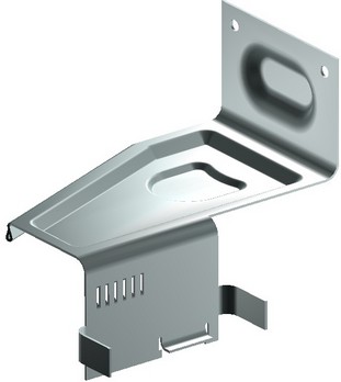
You can create forming features on bodies using Forming features operation. Forming feature from standard or custom libraries can be used.
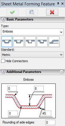
To create one of frequently used sheet metal forming features, use the command SMF: Create Sheet Forming Metal Feature:
Icon |
Ribbon |
|---|---|
|
3D Model → Special → Sheet Metal → Forming Feature |
Keyboard |
Textual Menu |
<SMF> |
Operation > Sheet Metal > Forming Feature |
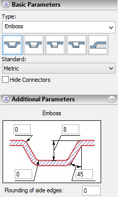
Type of a sheet metal forming feature can be selected either from the quick access drop-down list or by clicking the corresponding icon. If you select type from the list and it is not presented among icons below, the new icon will replace the last right icon. Item “Type” in the drop-down list allows you to select element from custom libraries added to selection list.
The content of the selection list is linked with the value of the Standard field and will update accordingly. You can select sheet metal forming features library using option:
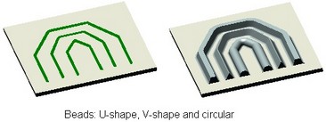
More information about configurations can be found in “Holes” chapter. A special library of typical forming elements is used for forming feature creation, “Sheet Metal Features”, shipped together with the system. If necessary, the library can be appended with custom elements. |
|
If linear units are set to inches in the command ST: Set Document Parameters, on the tab “3D”, then the forming features will be used from the library Sheet Metal Features Inch.
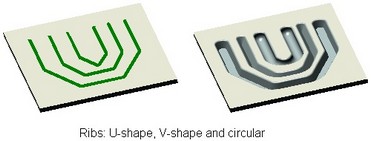
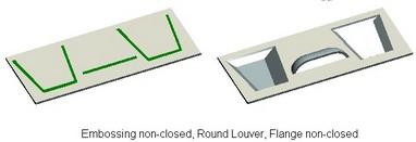
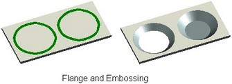
The operation is based on a flat 3D profile lying fully on one of the workpiece faces. Depending on a forming feature, the profile should satisfy different requirements. Thus, for example, majority of the standard forming features (except “Embossing” and “Flange”) strictly require a single-contour profile. The elements “Flange non-closed”, “Embossing non-closed” and “Louver” require an open profile, “Embossing” and “Flange” – strictly a closed one, while the rest of the forming features can use either a closed or an open profile.
Creating typical sheet metal forming features
To create a forming feature, do the following steps:
1. Select a source 3D profile for the operation. The profile selection mode is activated automatically upon entering the command. This is indicated by the pushed automenu option:
![]() <A> Select 3D Profile
<A> Select 3D Profile
To select a profile, click one in the 3D scene by The source profile can be selected automatically, when calling the command while drawing on the active workplane or from the context menu of an appropriate-type 3D profile. 2. In the command property window, select the desired forming feature from available in the library. The dialog of the selected forming feature parameters will be displayed in the lower portion of the window. 3. In the dialog of the selected forming feature parameters (displayed in the operation property window), define the required parameter values. The parameters dialog for each forming feature has a schematic chart of the feature being created with input boxes for all geometrical dimensions. To define a dimension, placed the pointer in the respective input box in the chart and enter the desired value. 4. Confirm operation creation. |
|
More information about forming features creation can be found in “Create custom elements for sheet metal and holes libraries” chapter.