Convert Solid to Sheet Metal |
  
|
Convert Solid to Sheet Metal |
|
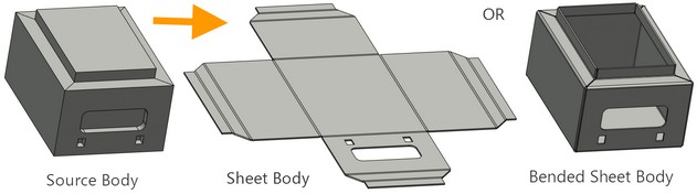
The «Convert Solid to sheet metal» command is used for quick creation of bodies from the sheet metal on the basis of solid bodies.
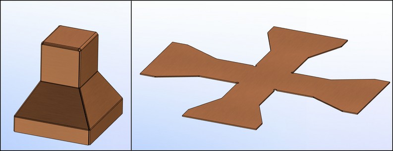
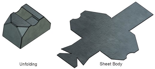
The result of execution of the «Convert Solid to sheet metal» operation is the sheet body or bended sheet body that retains the shape of the original object.
Main Concepts. Operation’s Capabilities
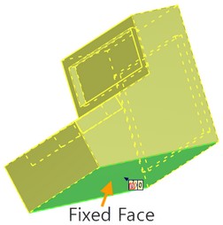
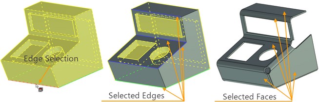
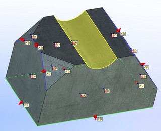
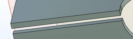
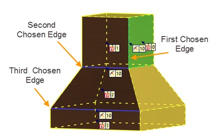
This operation significantly simplifies the creation process of flat and 3D bodies from the sheet metal. Solid bodies with flat faces can be used as the source bodies for creation of this operation. Fixed face Creating of the body is carried out relative to the first selected face which is considered fixed and defines location of the plane. This face is called a fixed face. Any flat face of the body can be selected as a fixed face. The edges for bending which will participate in the operation are specified relative to the fixed face. After being selected the fixed face is highlighted with a green color.
|
|
Edges for bending
After selection of the fixed face it is required to select edges for bending. Either the operation of fillet with a specified radius value or the operation of sheet body creation by the arc length of the resulting fillet is applied to the edges selected for the operation.
One of the edges of the fixed face should be the first among the selected edges. After selection of the edge its second forming face is included into the operation. Other edges of this face immediately become available for selection as the edges for bending. Thus, in order to select the face it is required to indicate at least one edge adjoining the face.
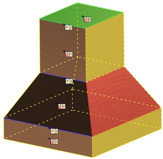
All faces to which the selected edges belong are highlighted with grey color. The faces that do not participate in the operation are highlighted with yellow color.
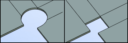
When selecting edges it is important to ensure that the resulting sheet elements do not penetrate into each other. This is related to the fact that with the help of this operation it is impossible to obtain self-intersecting flat template.
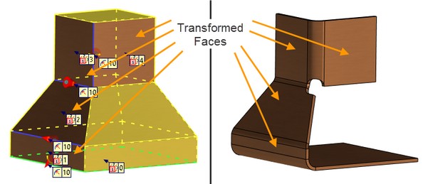
Creating thickness
For each selected face an equidistant surface is created at the given distance equal to the specified thickness. The new surface is constructed from inside of the face. After completion of the operation all selected faces are transformed into the sheet material, and the faces which were not selected are removed.
Removing faces
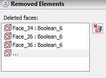
By default all faces highlighted with yellow color will be removed upon creation of the operation. If it is required to remove already selected face, the following option is used
|
<D> |
Select removable faces |
The selected face is added to the «Removed Elements» section in the properties window and is marked with red color once the face is selected in the list. In order to cancel selection of the face for removal it is required to go to the properties window «Unfold Parameters» to the «Removed Elements» section, select the face and press the «Delete face from list» button |
|
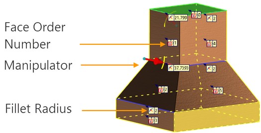
Draggers and markers
For each edge selected for the operation, the dragger and marker appear in the scene. The fillet radius is shown on the fillets markers. It can be changed if we click on the marker with the left button of the mouse. If we press on the dragger’s arrow and move it forward or backwards, then we can also change the radius value. At the same time the arc by which the fillet is created will be shown.
All faces are numbered in the order of their selection for participation in the operation. The number is displayed on the marker («0» − this is a fixed face, «1» − face forming the first edge from the selected edges etc.).
Elements being used
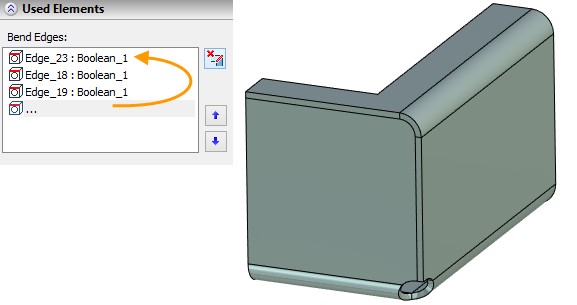
All edges and faces of the body that are used in the operation are selected manually. Their list is displayed in the «Used Elements» section of the properties window.
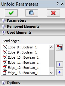
The edges selected for the operation are assigned the sequence numbers («Edge_2», «Edge_3» etc.). The number is assigned to each newly selected edge sequentially, i.e., if the edge selection is cancelled, and afterwards the same edge is selected again, it will have a different sequence number.
The «Delete bend edge» button ![]() located to the right on the «Used Elements» section allows us to exclude the bend edge selected in the list from the operation. It is also possible to delete the bend edge from the list by selecting it with a mouse click and by pressing the <Delete> button on keyboard. In the work window the edge selection can be cancelled by clicking on it again with the left button of the mouse.
located to the right on the «Used Elements» section allows us to exclude the bend edge selected in the list from the operation. It is also possible to delete the bend edge from the list by selecting it with a mouse click and by pressing the <Delete> button on keyboard. In the work window the edge selection can be cancelled by clicking on it again with the left button of the mouse.
The buttons up and down located to the right below the «Delete bend edge» button are used for changing the order of bending. The use of this option is described below.
Creating «Convert Solid to Sheet Metal» Operation
For transforming the body into a sheet metal the <Operations|Sheet Metal|Convert Solid to Sheet Metal> command is used:
Icon |
Ribbon |
|---|---|
|
3D Model → Special → Sheet Metal → Convert Solid to Sheet Metal |
Keyboard |
Textual Menu |
<SMS> |
Operation > Sheet Metal > Convert Solid to Sheet Metal |
To create this operation it is first required to carry out the following sequence of actions:
1.Select the fixed face of the body
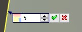
2.Specify thickness of sheet material and fillet radius of the faces, otherwise these values will be selected automatically from the status
3.Select edges which will participate in the operation
4.Enable or disable the options: bend result, remove bend edges, keep source body (if necessary)
5.Specify additional capabilities of the operation: relief type, gap type, ripping gap (if necessary)
6.Confirm creation of the operation.
Parameters of the Operation
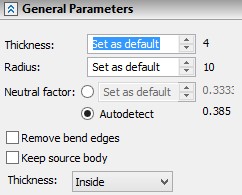
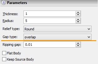
Thickness – allows us to specify the thickness of the resulting sheet metal. The thickness can be specified automatically or manually.
Radius – allows us to specify the fillet radius of sheet metal faces. The radius can be specified automatically or manually. If the «Bend result» option is disabled and the flat body is created, the radius is taken into account when calculating the value of the fillet’s arc that is unfolded on the plane.
Neutral factor. Controls neutral factor definition
Remove bend edges. To activate this option, it is required to enable the flag in the corresponding field on the «Parameters» section. When this option is enabled, an absolutely smooth sheet body without lines at the places of bending is created. When this option is enabled, the «Bend result» operation is not executed.
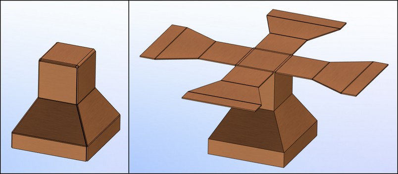
Keep source body. To enable this option, it is required to enable the flag in the corresponding field on the «Parameters» section. When the option is active, the source body is added to the result of the current operation. This option is convenient in estimating how the bent workpiece fit in with the overall dimensions of the source body.
Thickness direction. Option allows to specify thickness direction for the sheet body. Inside, outside and symmetric modes are available.
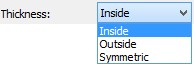
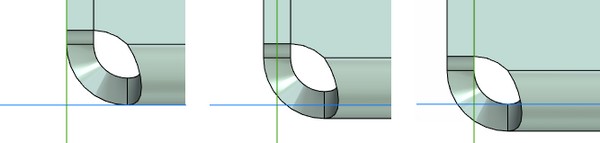
Inside |
Symmetric |
Outside |
Gaps group:
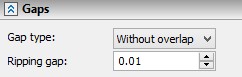
Gap type – this parameter defines location of adjoining sheet faces upon bending relative to each other. From the drop down list it is possible to select one of the three options: without overlap, overlap, reverse overlap. This parameter is used when the «Bend result» option of the automenu is used.
|
|||
Without overlap |
Overlap |
Reverse overlap |
|
Ripping gap –allows manually specifying the distance between sheet faces adjacent to each other.
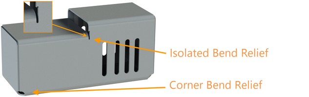
Bend relief group:
Corner, Isolated. Options allow to specify the shape of holes for relieving the stresses in the sheet metal for corner and isolated bend reliefs correspondingly. Three bend relief types are available: circular, square and welding. Welding type is unavailable for isolated bend relief.
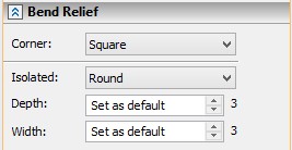
Width and Depth. Allows to set width and depth of an isolated relief.
Radius of the circular hole is equal to the radius specified in the parameters. The square hole is constructed by three or more points of intersection of the given radius circle with the planes selected for the operation.
For 3D sheet bodies, the square holes are created only on the non-rounded faces.
When welding type is selected the same distance is specified on straight and curved sections at the junctions.
Automenu Options:
The following automenu options are available:
|
<F5> |
Preview operation result |
|
<K> |
Selected fixed face |
|
<R> |
Cancel selection |
|
<B> |
Select bend edges |
|
<D> |
Select removable faces |
|
<E> |
Edit rip edges |
|
<2> |
Change relief type at selected vertex |
|
<C> |
Bend result |
To select fixed face, relative to which the operation will be carried out, the option is used:
|
<K> |
Selected fixed face |
To cancel selection of all faces and edges participating in the operation, we use the option:
|
<R> |
Cancel selection |
This option returns to the start of the operation. A fixed face and edges must be selected again. The values already specified in the «Parameters» section (thickness, radius, etc.) will not be changed.
For selection of edges for bending which are participating in the operation, the following option is used:
|
<B> |
Select bend edges |
After this option is enabled it is required to select the edges adjacent to the faces participating in the operation, starting with the edges of the fixed face. The indicated element will be highlighted and the tooltip with name of the element will appear next to the cursor. For selection it is required to press ![]() .
.
To change the value of the gap and the type of the overlap for each face individually, the option is used:
|
<E> |
Edit rip edges |
After this option is enabled it is required to select the edge on the common boundary of two faces participating in the operation and, in the window that appears, indicate the value of the gap and, if necessary, select one of the three types of the overlap.
|
||
Overlap |
Without overlap |
Reverse overlap |
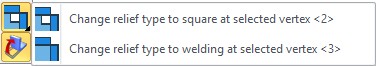
To specify a relief type in the selected vertex use option:
|
<2> |
Change relief type at selected vertex |
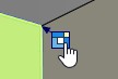
For the selected vertex you can select a relief that differs from the default relief type of the operation. A relief type can be chosen from the drop down list of the option before the vertex selection. The specified relief type may be changed by clicking on the special marker.
To exclude faces from the operation, the following option is used:
|
<D> |
Select removable faces |
After selection of the faces participating in the operation, it is possible to enable this option of the automenu and indicate the selected faces that will be removed as a result of the operation. The edges adjacent to the faces being removed become unavailable for selection.
To switch between creation of flat and 3D body, the «Bend result» option is used. For activation of the option is used:
|
<C> |
Bend result |
If this option is enabled, the sheet body will retain original shape of the object. Otherwise, the body will be located on a plane which will be determined by the fixed face.
|
When the «Bend result» option is enabled, after creation of the operation, in addition to conversion to sheet metal, one more operation – «Rebend» is added to the constructions tree.
If we change the properties of already created operation, the «Bend result» button of the automenu become inaccessible. This is done in order not to destroy logic of operations execution when other operations are present in the «3D model» window after the «Convert to Sheet Metal» operation.
|
For previewing the result of the Boolean operation, and also the changes introduced by the Boolean operation, the automenu option of the preview must be used:
|
<F5> |
Preview operation result |
Operation Execution Example
The use of the «Convert solid to sheet metal» operation is demonstrated in this example. Moreover, we consider the case when it is required to change the order of bending.
After creation of the cube in 3D window, we go to the parameters of the sheet metal
Icon |
Ribbon |
|---|---|
|
3D Model → Special → Sheet Metal → Defaults |
Keyboard |
Textual Menu |
<SMP> |
Operation > Sheet Metal > Defaults |
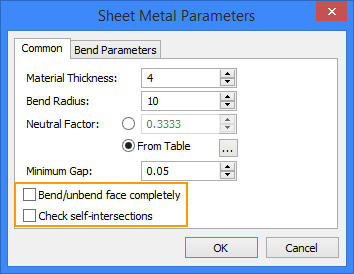
We remove the flags from the «Bend/unbend face completely» and «Check self-intersections» options. This is done for the system to be able to display the resulting body on the screen when self-intersections of the metal sheets occur. If the flag are retained, the system will not be able to create a self-intersecting body and issue the error message.
For creation of the «Convert Solid to sheet metal» operation, the command must be invoked:
Icon |
Ribbon |
|---|---|
|
3D Model → Special → Sheet Metal → Convert Solid to Sheet Metal |
Keyboard |
Textual Menu |
<SMS> |
Operation > Sheet Metal > Convert Solid to Sheet Metal |
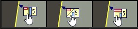
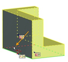
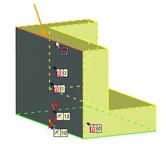
The order in which the construction elements are selected for creation of the operation is shown in the figure below. In the first step the fixed face was chosen (picture 1). Next, three edges of the body were chosen in order (pictures 2 – 4 ).
|
|
|
Fixed face selection |
First edge selection |
Second edge selection |
|
|
|
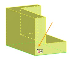
Third edge selection |
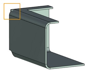
Result |
Result |
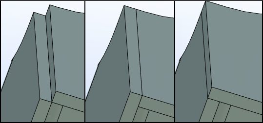
Before execution of the operation in the properties window on the «Parameters» section it was indicated that the edges of the sheets must lie on each other with the overlap.
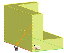
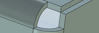
After execution of the operation, we obtained the solid body in which two sheets with the angles that are not deformed intersect the rounded face (Result). This is caused by the incorrectly specified sequence of body bending.
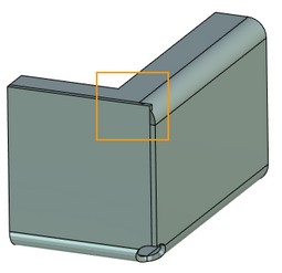
For these very cases it is convenient to use the change of order in bending of edges. This allows us to avoid self-intersections of bodies. At the same time there is no need in redefining of the edges manually.
In the «Used Elements» section of «Parameters» window, the edge selection order for the operation is shown. Using the up ![]() and down
and down ![]() arrows we change the order in which bending is executed.
arrows we change the order in which bending is executed.
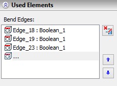
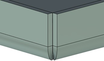
Now we move the last edge selected for the operation up by two lines by selecting the desired edge and pressing the up arrow, and afterwards we repeat the creation of the operation. Now the sheets are smoothly adjoining each other and do not intersect.