Lofted Bend |
  
|
Lofted Bend |
|
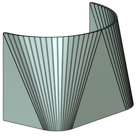
Lofted bend operation allows to create complex sheet bodies based on two sections.
You may call the operation via command:
Icon |
Ribbon |
|---|---|
|
3D Model → Special → Sheet Metal → Lofted bend |
Keyboard |
Textual Menu |
<SML> |
Operation > Sheet Metal > Lofted bend |
To create a new sheet body using this operation you need to select two non-closed sections located on two parallel planes. Sections can consist of smoothly docked arcs and straight lines.
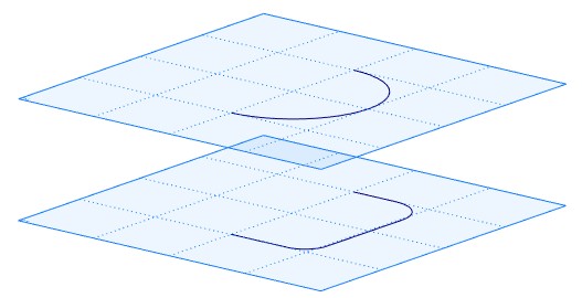
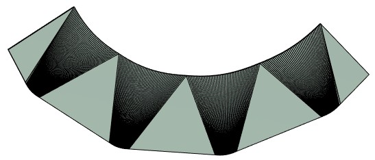
There can be different number of arcs and straight lines in the sections. Arcs are connected with arcs, straight lines are connected with straight lines.After that, cylindrical bend segments are created.
A body produced as a result of this operation can be unbent with SMU: Unbend operation.
Operation Creation
Non-closed Sections
You may create a sheet body using non-closed sections.

You can select sections using:
|
<U> |
Select first section |
|
<V> |
Select second section |
A sheet body may be created using part of the contour. For this purpose you should select starting point and direction for the both of the contours. The directions should coincide.
To select starting points for sections use options:
|
<1> |
Select starting point for the 1st section |
|
<3> |
Select starting point for the 2nd section |
To select the direction use options:
|
<2> |
Select direction for the 1st section |
|
<4> |
Select direction for the 2nd section |
In the example a workplane is selected to define the direction.
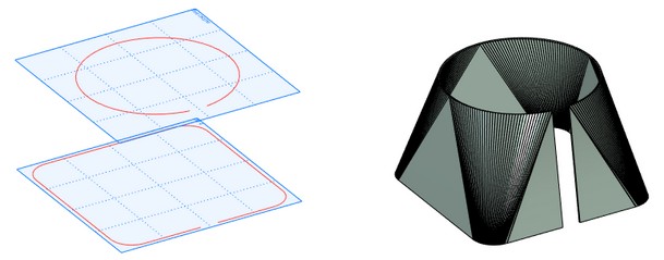
Closed Profiles
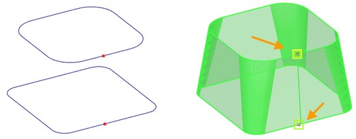
You can create sheet metal body from two closed contours.
For each of them you need to select a starting point and a direction for bends creation.
For closed profiles, you need to define a parting line using starting points.
To select starting points for sections use options:
|
<1> |
Select starting point for the 1st section |
|
<3> |
Select starting point for the 2nd section |
To select the direction use options:
|
<2> |
Select direction for the 1st section |
|
<4> |
Select direction for the 2nd section |
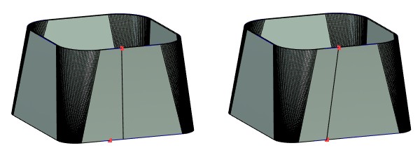
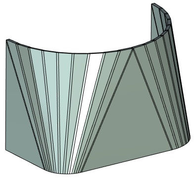
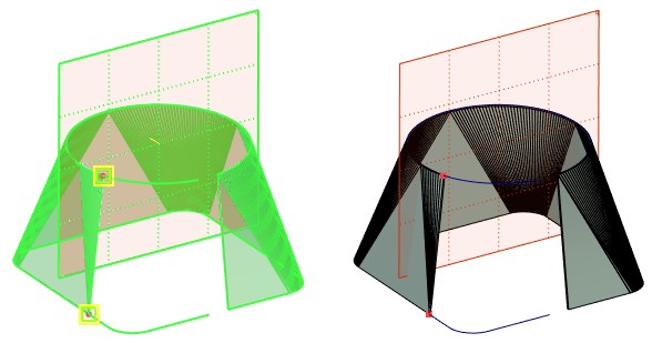
There are several ways to define parting line. One way is to select a starting point on the section and a direction for the section to define a parting line.
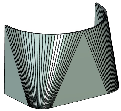
Other way is to select two starting points on the sections and specify a direction.
The result will differ according to the selected way,
|
|
Starting point and direction are selected on the upper section |
Two starting points on the sections and direction are selected |
Command Parameters
General Parameters section:
When you use Faceted approximation option, a surface body is created. The body can be converted into a sheet metal body.
Thickness defines thickness of the created sheet body.
Radius defines radius of all bends of the created body.
The values by default are set in SMP: Parameters.
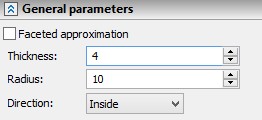
Direction. Allows to determine direction of body creation corresponding to the plane created between two selected sections: Inside, Outside, Symmetric.
Additional settings section:
Accuracy. The smaller is the value, the higher is the accuracy. High accuracy increases the number of bends, but requires more time to create the body.
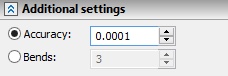
Bends. Allows to configure number of bends, which are created in the segments formed by two arcs or straight lines.
|
|
|
|