Unbending |
  
|
Unbending |
|
Once the desired part model is created, you can use a special Unbend operation. It allows "unfolding" the part and getting the unfolded pattern model of the design. This may be needed, for example, for drafting the part unfolded pattern.
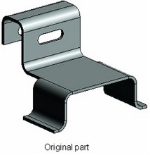
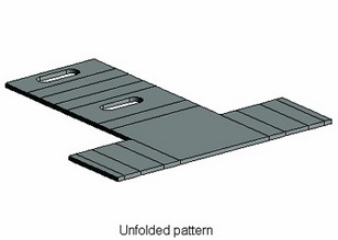
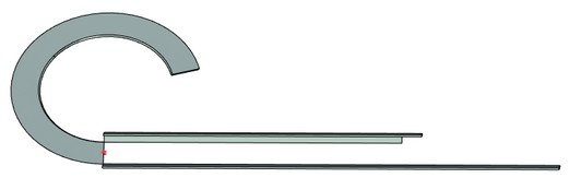
This operation is more than just unbending genuine sheet metal parts. Imported bodies can also be "unbent", as well as cylindrical faces resulting from extrusion or rotation. Several bends can be unbent simultaneously.
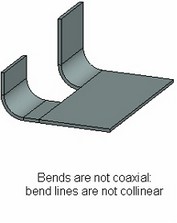
Bends to be straightened are selected by picking cylindrical faces created by bending. You can unbend all coaxial bends by selecting just one of them.
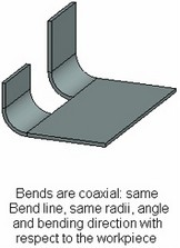
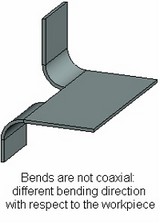
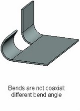
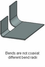
Coaxial are bends satisfying the following conditions: they belong to one body, use collinear bend lines, have the same radius, angle and direction of bending with respect to the workpiece.
When unbending, the workpiece neutral layer factor is significant. If a part is being unbent that was not bent from sheet metal, the user shall define the neutral factor in the command parameters.
Unbend operation preserves all topology previously created by bending. That means, the number of faces and edges is the same before and after unfolding. This allows determining bend areas in the resulting flat pattern and use those, for example, in repeated bending.
Unbend Operation Creation
To flatten bends, use the command “SMU: Unbend Bend”:
Icon |
Ribbon |
|---|---|
|
3D Model → Special → Sheet Metal → Unbend |
Keyboard |
Textual Menu |
<SMU> |
Operation > Sheet Metal > Unbend |
Bends and other cylindrical body elements subject to flattening are selected by picking their defining cylindrical faces. Upon launching the command, the option is automatically activated in the automenu for selecting faces to flatten:
|
<E> |
Select cylindrical bend face |
To select a face, simply click it with ![]() in the 3D scene or pick the respective operations in the model tree. The selected faces are highlighted in green (by default).
in the 3D scene or pick the respective operations in the model tree. The selected faces are highlighted in green (by default).
When you select closed face of the body the following option becomes available:
|
<P> |
Select node to define split surface |
The option allows to select a 3D node to create a split surface.

You can determine unbending direction for closed contour using option:
|
<D> |
Select unbending direction |
All bends in a body can be quickly selected by the option:
|
<A> |
Select operation |
The portion of the part left still in unbending is determined by the system automatically. By default, such face is marked yellow in the 3D scene. To alter the result, the still face can be manually selected by the automenu option:
|
<K> |
Select immovable unbending face |
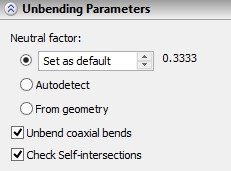
The Neutral factor for unbending selected faces is picked from the parameters of the respective bends. In the cases when the faces were created by other means than bending, the Neutral factor shall be defined in the command dialog in the property window. Autodetect. The factor is determined from the table according to the model thickness. From geometry. The factor is determined according to the neutral factor for one of the bended faces, used in unbending. All faces used in the unbending operation have the same neutral factor. The flag Unbend coaxial bends (set by default) forces unbending of all bends coaxial with the selected one. When cleared, only the selected bends are flattened. |
|
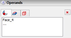
Check self-intersections. This parameter is important when creating the «Bend» parameter. It allows you to monitor self-intersection of bent sheet faces. When the flag is set, system will not create bend that intersects with the source body. All deformed faces, fixed faces and operations are displayed in the Operands section. |
|