Bending. Main Concepts and Capabilities |
  
|
Bending. Main Concepts and Capabilities |
|
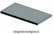
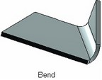
"Bend" operation imitates one of the main shape-defining sheet metal operations, bending. The operation is applied to a solid body satisfying the above conditions on the sheet metal workpiece.
Types of bending
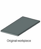
Bend operation supports various types of manipulation with a sheet metal workpiece, such as: bend the whole workpiece along a line; bend a protruding portion thereof; make an incision and bend an inner portion of the workpiece. If the flat pattern shape is not known in advance, the user can start modeling from a simple box-shape workpiece, attaching to it rectangular pieces as necessary and bending those right after.
All these actions are supported by the four bending modes. You can select a mode in the operation properties window.
●Bend - bends the whole workpiece along a specified line.
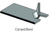
●Cut and Bend - makes an incision, and then bends a portion of the original workpiece.
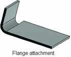
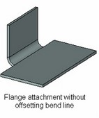
●Attach Flange - attaches a flange of the specified size to the original workpiece. The attached flange is bent about its attachment line.
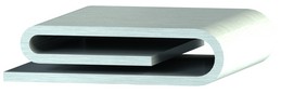
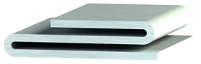
●Hem – attaches a hem of the selected shape to an outer contour of worpiece.
General bending parameters
Bending of any type is affected by the following parameters of the operation:
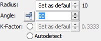
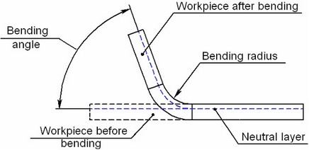
● Radius of bending – the radius of the base face in the bended area;
● Angle of bending – the angle between the original and the bent position of the bent portion of the workpiece;
● Neutral factor (the neutral layer factor) – a parameter defining the position of the neutral layer in the workpiece. The neutral layer of a workpiece is its section parallel to the main faces, whose geometry does not change in bending. All geometrical parameters of bending (the bending radius, the length of the attached piece, positioning with respect to a specified bending line) are calculated with respect to the neutral layer. This parameter value can be defined by the system automatically, based on the table of Neutral factor values versus the ratio of the bending radius and the workpiece thickness. The Neutral factor dependency table can be manually modified by the user as desired.
Main concepts of bending
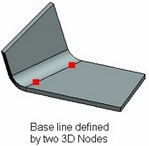
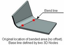
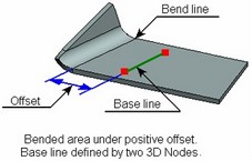
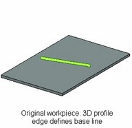
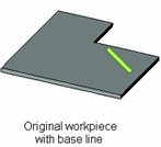
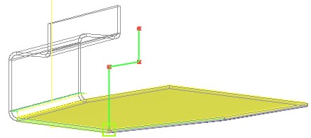
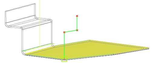
Bend operation is defined by a base line, specified by two 3D points or a 3D object suitable for defining a straight line. The base line serves several purposes: it allows the system to define the body being deformed and the base face of bending, determines the position and size of the bended area, determines the possibility of creating one or another type of bending.
The base line must lie in the plane of one of the workpiece faces being bent (normally, the top or bottom face). The base line does not have to fully fit within the boundaries of a base face; however, at least some its portion must belong to the face.
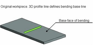
The face that holds the base line is the base face of bending. The base face is used as the base reference when defining bending parameters. The body to which the selected face belongs is actually the workpiece being transformed.
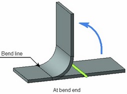
Transformation of the workpiece is done in the following way. The base face and all original body are divided by the base line into three portions: still portion, bent portion (the bended area) and the turned portion. The still portion is left unchanged by the operation. The bent portion is replaced by a cylindrical element of the appropriate shape, with the radius equal to the bending radius. The turned portion is turned about the axis of the bent portion by the bend angle.
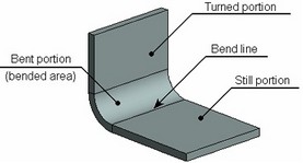
The border line between the still portion of the workpiece and the bended area will be referred to as Bend line.
Bend line position relative to base line
The kind of bend line (its length and position) depends on the specified base line, and type and parameters of bending. The bend line can have the same length as the base line, or be longer than the other one, passing through all base face, or, on the contrary, be shorter than the base line. The position of the bend line with respect to the base line is defined by the location of the bended area with respect to the base line of the bending.
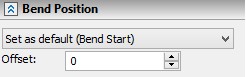
A position is specified in Bend Position section of the properties window of the operation.
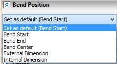
There are following possibilities:
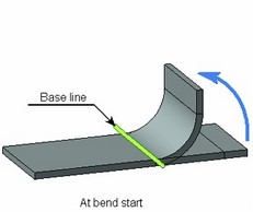
- Bend start - The beginning of the bended area is aligned with the base line (used as default);
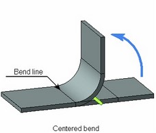
- Bend center - The bended area is centered about the base line;
- Bend end - The end of the bended area of the workpiece is aligned with the base line.
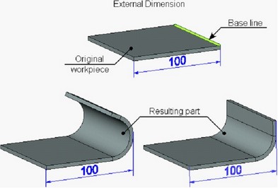
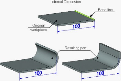
-External Dimension/Internal Dimension – the bend area is positioned in such a way that the overall size of the resulting part measured from the outer/inner wall of the attached flange to the opposite trimmed face of the part remains the same as for the original part. These options are used only in the mode “Attach Flange” for attaching the flange to the edge of the part with the bend angle not smaller than 90°.
The base line location at the start of the bended area is most common. This configuration will be used throughout the further description of Bend functionality.
Shifting the bend line off the original position
An auxiliary parameter Offset allows shifting the bended area and, therefore, the bend line off the base line. The bended area shifts to either side of the original position, depending on the offset sign. Positive offsets are towards the bent (attached) portion, negative – away from it.
Shifting the bend line often helps in the cases, when the user is not satisfied with the location of the bended area, or when bending is outright impossible in the current location.
Offsets from base line ends
The length of the bend line can be adjusted by Offsets from the ends of the base line.
Offsets are specified in the corresponding section of properties window.
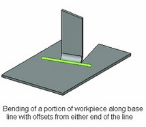
Offsets are introduced in the cases when the selected base line exactly defines the desired position of a bend, but is longer than the portion of the workpiece to be bent.
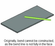
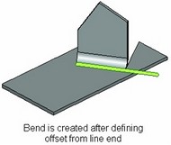
In some cases, use of offsets allows creating a bend even if the original base line was incorrect. This could be, for instance, the situation, when the base line for the bend does not fully fit in the face of the workpiece. Without using offsets, bending cannot be created in this case. By offsetting from the line end, one can reduce the length of the bend line in such away, that the bend area fully fits in the bending base face.
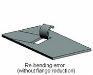
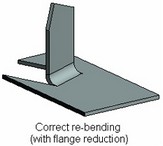
Flange Reduction
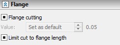
In many instances of bending or attaching a flange, the side walls of the bent “ear” touch the faces of the workpiece base. During further manipulations with such a bend, the bent “ear” may “stick” to the workpiece elements it is touching. This causes errors in successive unbendings and rebendings of the model. Should such situation occur, we recommend using capability of automatic width reduction of the bent or attached portion in order to introduce gaps between it and faces of the workpiece base. The reduction amount is constant and is set to 0.05 millimeter on each side of the “ear”.
When attaching a flange inside the workpiece with material removal by the length of the flange, the flange length will also be reduced by the same amount as the width.
Corner Relief in Sheet Metal
When making parts by bending sheet metal, stresses develop in the metal around bend corners. To treat stresses that may cause cracking, special slots can be introduced around the bend.
“Bend” operation supports creation of such slots – reliefs, introduced automatically when bending and attaching flanges. Introduced reliefs can have round or square shape.
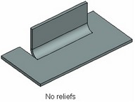

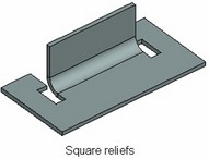
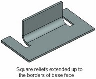
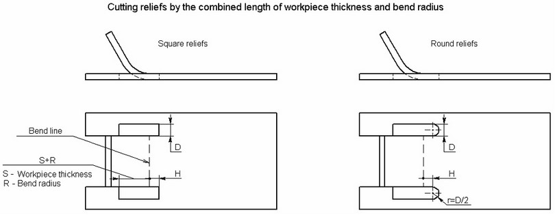
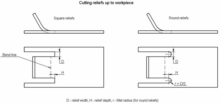
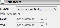
Dimensions of a relief slot are controlled by two parameters: “width” and “depth”. For a square relief, those define the width of the slots and the length of the slot portion ahead of the bended area, respectively. In the case of the around relief, the length of the head portion of the slot is increased by the radius of the end fillet. The fillet radius is equal to half the slot width.
The rear portion of a slot of any type can be arranged in one of two ways:
-have the length equal to bend radius plus workpiece thickness;
-extended up to the borders of the workpiece (or to the end of the punch, if attaching a flange inside the workpiece with material removal by the flange length).
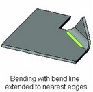
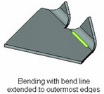
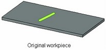
Bend
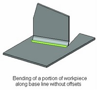
In plain Bend, the original workpiece is just bent along the base line, without incisions or material removal. In this type of bending, the bend line is formed by extending the base line segment at either end until intersection with side edges of the base face. There are two ways of extending the base line:
● Through the face – the bend line extends to the outermost edges of the base face.
● To nearest edges – the bend line extends to the nearest edges of the base face (only a local protrusion of the workpiece is bent).
In plain Bend, offsetting from the ends of the base line is not supported.
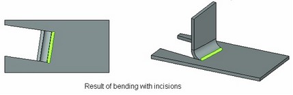
Cut and Bend
This is bending with incisions, when a portion of the workpiece between cuts is bent. The cutting lines of the bent portion originate from the ends of the base line (or from the points defined by offsets from the ends of the base line), perpendicular to the base line and extending to the boundaries of the base face.
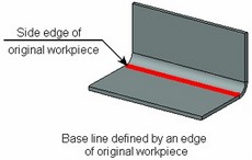
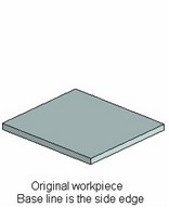
This type of bending requires the bend line to be a segment lying fully within the base face. You can also define the base line by one of the side edges of the workpiece. However, in this case you must define an offset for the bend line.
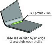
A special type of cut-bending is profile bending. An open 3D profile created on a face of the workpiece defines the pattern for the flange being bent. The base line is determined by the profile end points.
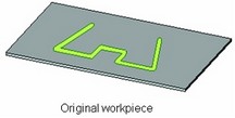
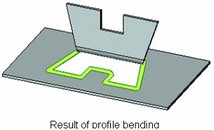
In profile bending, the base line always defines the start of the bent area. You cannot specify any offset for the bend line or offsets from the ends of the base line in this case.
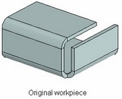
Flange attachment
Attach Flange mode is convenient in the cases when you do not know in advance even an approximate pattern of the part being designed. In this case, start with a simple-shape workpiece (commonly, a flat block). Then, work it out by adding rectangular "ears" of the specified length in the desired locations, and bending those off. The thickness of the attached "ears" is the same as the thickness of the workpiece, while the width is defined by the base line (including offsets).
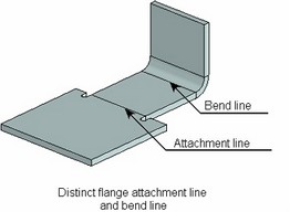
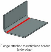
To proceed with the description of attaching, let us introduce an additional term for this type of bending –Attachment line. By this term, we mean the line along which the flange is attached to the original workpiece. Initially, when creating a bend, the attachment line coincides with the bend line. In other words, the flange is bent along the same line as it is attached. In this way, the position and the length of both lines is defined by the base line of bending (including offsets) and by the location of the bended area with respect to the base line. The attachment line and the bend line can be separated by offsetting the bend line from the base line. In this way, the bended area of the flange will be shifted away from its attachment.

Contour Flanges
A contour flange can be attached for workpieces. A contour flange is the sheet metal operation, which shape is specified by a guide curve. The result of this operation is attached to the edges of the base sheet body, forming a single model.
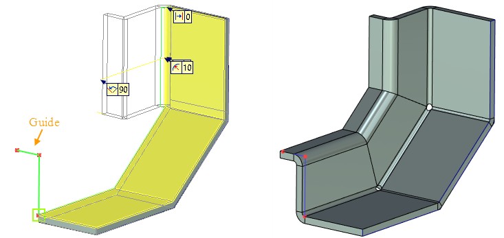
You need to select a profile or a path as a flange guide to determine the flange geometry. Flange guide cannot be closed. All points should locate in one plane. The flange guide can be set by straight lines or circular arcs.
It is necessary to select a rib to which the contour flange will be attached and a flange guide. After that you need to select adjacent point and profile direction. If the guide is already adjacent to the rib, the contour flange is created immediately after guide curve selection.
Flanges can form a closed contour. You can specify bend relief and gaps for the flange junctions.
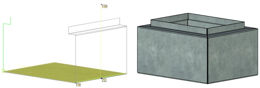
Contour Flange Creation
To create a contour flange you should:
1.Select edges for the operation using Add Edges ![]() option.
option.
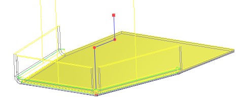
2.Select guide – existing profile, route or path using Select flange guide ![]() option.
option.
3.If the selected guide is already adjacent to the rib, the contour flange is created immediately after guide curve selection.
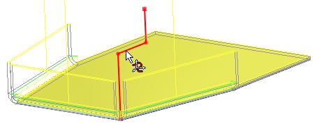
Otherwise, you may use Select adjacent point ![]() option and select a point on the guide.
option and select a point on the guide.
Upon creating several flanges for a single workpiece, manipulators and decorations will be displayed only for the last created flange. This is done in order not to complicate the visual perception of the model.
4.A direction of the flange can be changed using Select profile direction ![]() option. You need to specify a direction using existing geometry.
option. You need to specify a direction using existing geometry.
Shifting bend line off the base line
The result of attaching a flange with offsetting the bend line from the base line depends on the offset direction (sign).
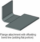
When the offset is positive (that is, offsetting from the workpiece onto the flange), the attachment line is unchanged, that is, defined only by the position of the base line. At the same time, the flange bend line shifts by the amount of the offset. As a result, the flange being attached gains additional flat portion whose length is defined by the offset. This length of the flat portion is not included in the flange length defined in the operation parameters.
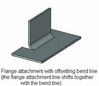
When the offset is negative (that this, offsetting onto the side of the workpiece), both lines shift – the attachment and the bend line.
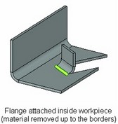
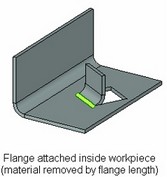
Flange attachment inside workpiece
In most cases, flanges are attached to one of the side edges. This is done by selecting the desired edge of the workpiece as the base line, without offsetting. However, attachment can be done inside workpiece as well. This would happen if the base line were defined by an edge of a 3D profile lying within the face of the workpiece, or if attachment were made to a side edge with a negative offset. In this case, the material of the workpiece on the way of the attached flange is removed. The width of the removed portion is determined by the perpendiculars to the base line (including offsets), constructed on its ends, just like in the case of incision bending. In this way, two kinds of removal are possible: either all material is removed up to the extents of the workpiece, or just the portion thereof by the length of the attached flange.
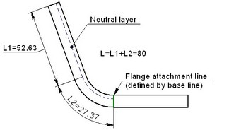
Calculation of attached flange length
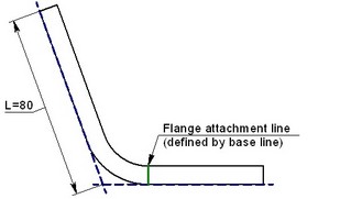
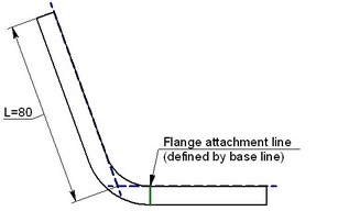
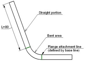
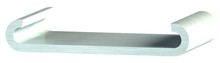
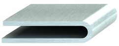
The length of the attached flange can be calculated in four ways: by neutral layer, by external side, by internal side or by flat part of the flange being attached. The following diagrams show the respective cases of length calculation when attaching a flange of length L=80 millimeters.
|
|
Flange length calculation by neutral layer |
Flange length calculation by external (outer) side |
|
|
Flange length calculation by internal (inner) side |
Flange length calculation by flat portion |
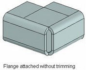
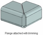
Intersecting ends trimming
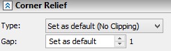
When attaching a flange, intersections may occur between the flange and the workpiece. In such a case, automatic trimming can be performed. Trimming is done in such a way to leave a diagonal gap of the specified width in the intersecting area.
Trimming is possible if the flange and the intersected portion of the workpiece have the same thickness and lie in one plane. Certain exceptions from these rules are allowed, such as tolerance on flange thickness and bending angle when matching with the workpiece.
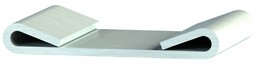
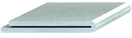
Hem
Operation attaches a hem of the selected shape to an outer contour of a worpiece. You can select several workpiece ribs that belong to the same face. Flanges can form closed contours.
There are six types of hem available:
Rolled |
Open |
Teardrop |
Closed |
Double |
S- shaped |
Creating various types of Bend
The command SMB: Create Bend is used for creating various types of Bend:
Icon |
Ribbon |
|---|---|
|
3D Model → Special → Sheet Metal → Bend |
Keyboard |
Textual Menu |
<SMB> |
Operation > Sheet Metal > Bend |
Upon calling the command, do the following steps:
1.Define the bend line (if not selected automatically upon entering the command) and the bend type (if other than the system default). You can select several bend lines for Attach Flange and Hem operations.
2.Select Hem type (only for Hem operation).
3.If necessary, select a different face to bend and the side of bending. Not available for Hem operation.
4.Define the shift of the bend line and offsets from its ends. In this way, you adjust (if necessary) the location and width of the bent (attached) flange. Not available for Hem operation.
5.Modify (if necessary) the default Bend parameters (the bend radius and angle, Neutral factor, the flange length and the way of measuring it when attaching the flange).
6.Modify (if necessary) the default type and dimensions of reliefs.
7.Confirm operation creation.
Available options and parameters set can differ for various types of bend.
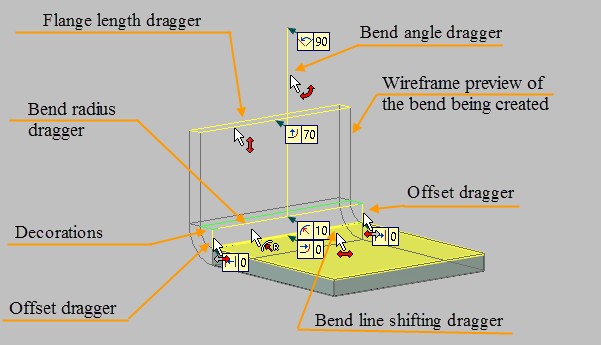
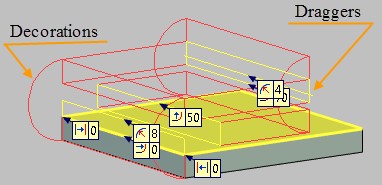
Auxiliary Bend elements displayed in the 3D scene
During bending (after selecting the base line), auxiliary graphic elements - draggers and decorations - are displayed in the 3D scene. Those schematically outline the shape and size of the bend being created. Additionally, each of those objects has its specific purpose. The draggers serve for modifying the bend dimensions directly in the 3D scene. The decorations let the user know whether the bend is possible or impossible under the specified conditions.
When the bend is possible, the wireframe preview image of the operation is displayed in the 3D scene over the blue decorations (by default).
Use of a dragger in bending is similar to using draggers in other 3D commands. As the pointer approaches to the dragger’s image, it gains a respective glyph. If you start moving the mouse with the depressed ![]() at such moment, the wireframe image of the operation being created will rubberband, and the respective parameter update in the property window.
at such moment, the wireframe image of the operation being created will rubberband, and the respective parameter update in the property window.
If the conditions are incompatible, no bend image is displayed, while the decorations change the color to the forbidding red (by default). In such a situation, either redefine the base line or fix the bend by shifting the bend line off the base line or offsetting from its ends. If, however, no decorations or draggers are displayed in the 3D scene upon specifying the base line, that means, the system could not find any face suitable for creating a bend about the specified base line. In this case, the only option is specifying a new base line.
Altogether, six types of draggers can be found in the 3D scene. Those are the bend angle, bend radius, bend line shift from the base line, length of the attached flange and offsets from either end of the base line. Depending on a particular bend type, some draggers may not be there. For example, the flange length dragger is only used when attaching a flange. In the plain bend, there are no draggers for defining offsets.
Defining bend line and bend type
To define the base line by specifying a 3D element suitable for describing a line, activate the following option in the command automenu:
|
<L> |
Select Line |
This option allows selecting a 3D element suitable for defining the base line of the bend. The drop-down list behind this option contains filters for selecting certain objects.
Add edges option is available for Attach Flange and Hem operations.
|
<M> |
Add edges |
The option allows to select several consequent edges that belong to the same face of the workpiece.
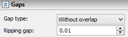
Gaps section appears in the Properties window if you select more than one edge. There you can set Gap Type and Ripping Gap.
To define the base line by two 3D points, use other automenu options (activated successively):
|
<S> |
Select first Vertex or 3D Node |
|
<E> |
Select second Vertex or 3D Node |
The set of admissible elements for selection is defined by the state of the filters in the drop-down lists of the described options.
The base line of the bend or one of its defining 3D points will be selected automatically, if calling the command while drawing on active workplane or from the context menu of the appropriate 3D element.
The base line for bending by profile is defined by the option:
|
<R> |
Select profile to bend |
Upon turning on this option, you can select a 3D profile that will be used as the pattern for bending the flange and simultaneously define the base line.
Once the base line is defined, the system assesses possible bending configurations. The faces will be identified that host the specified line. One of those faces is determined as the subject to bending and is highlighted in the 3D scene (by default – yellow). If the system identifies more than one suitable face, the automenu will provide the option for selecting other faces:
|
<F> |
Change active face |
After that, the system will tentatively define the type of bending, depending on the specified base line. The system choice depends on the type and way of defining the base line. For example, if a side edge was selected as the base line, the system will offer attaching a flange. If the ![]() option is used, the Cut and Bend mode will be set. In other cases, bend is assumed.
option is used, the Cut and Bend mode will be set. In other cases, bend is assumed.
The choice is reflected in the command dialog in the property window.
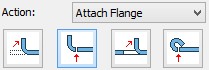
The system-offered choice can be altered by selecting another bend type from the list. The four options in the list correspond to the four described bend types: Bend, Attach Flange, Cut and Bend, Hem.
If the face is identified and a bend can be created in the specified bending area without adjustments (such as shifting or offsetting), then the wireframe preview of the future bend will be displayed in the 3D scene. The bent side of the workpiece (with respect to the base line) is selected by the system automatically. The user can alter it by the automenu option:
|
<D> |
Change the part to be bent |
When making a flange by profile, the bent part cannot be modified.
Defining bend parameters
The values of main geometrical parameters of a bend can be easily and quickly modified directly in the 3D scene by draggers. Those include the radius, angle, flange length, shift from the base line and offsets from its ends. Adjustments to the parameter values can be done in the property window or in the parameters dialog box invoked by the option ![]() .
.
All geometrical parameters of a bend can be defined in the property window. As was mentioned earlier, you can select there the bend type (the item “Action”), specify a numerical value of the bend radius and angle (the entries “Radius”, “Angle”). An additional button ![]() next to the angle input box allows quickly flipping the bending direction by 1800.
next to the angle input box allows quickly flipping the bending direction by 1800.
Neutral factor of the bend is controlled by the radio group “Neutral factor”: “From Table” – directs the system to take a value from the table (the resulting value is displayed next to the item); the other choice allows entering an arbitrary value.
The entry “Length” is accessible only when attaching a flange. It allows you to specify the length of the flange being attached. The way of measuring it is controlled by the parameter “Measured”.
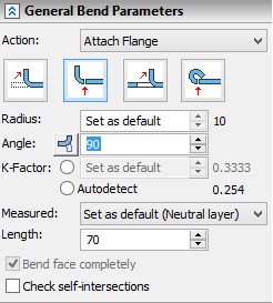
Bend face completely. This parameter is important when performing operations on the sheet metal of certain geometry (for example, when it is required to bend the sheet body with a cut along the specified line). When this parameter is enabled, the entire body along the selected line will be bent without violating the construction logic.
Check self-intersections. This parameter is important when creating the «Bend» parameter. It allows us to monitor self-intersection of bent sheet faces. When the flag is set system doesn’t allow creating bend, which result leads to an intersection with source body.
The group “Bend Position” permits selecting the desired location of the bend with respect to the bend line (“Bend start”, “Bend center”, “Bend end”, “Default”, “External Dimension”, “Internal Dimension”) and specify the line shift.
The rest of the parameters in the dialog are accessible only when bending with incision or attaching a flange (the settings “Cut and Bend” and “Attach Flange” in the “Action” combo box).
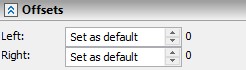
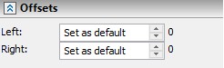
Offsetting from the ends of the bend line is defined in the group “Offsets”. Offset amounts from the left and right ends of the bend line are specified separately.
An additional flag Flange cutting is recommended in the cases when the side faces of the bend flange intersect with the faces of the workpiece base. This helps error-free unbending and repeated bending.
Trimming of the intersecting portions of the flange being attached and the workpiece base is defined in the group “Corner relief” (those parameters are available only when attaching a flange).
The group “Reliefs” in the dialog defines the shape and dimensions of relief slots created with the bend. First, select a relief type in the parameter “Type”: “Round”, “Square” or “None” (in the latter case, reliefs are not created). If one of the first to options was selected, the input boxes become accessible that define dimensions of the slots. Those are the depth (length) of the relief portion ahead of the bend line (“depth”) and the slot width (“width”). Setting the flag “Extend relief” makes the relief slots cut up to the borders of the workpiece.
Gaps section appears if you select more than one edge using Add edges ![]() option. There you can set Gap Type and Ripping Gap.
option. There you can set Gap Type and Ripping Gap.