Defining Parameters of Sheet Metal Operations |
  
|
Defining Parameters of Sheet Metal Operations |
|
Defining Parameters of Sheet Metal Operations
To define default parameters for the whole group of sheet metal commands, call the command SMP: Sheet Metal Operation Defaults:
Icon |
Ribbon |
|---|---|
|
3D Model → Special → Sheet Metal → Defaults |
Keyboard |
Textual Menu |
<SMP> |
Operation > Sheet Metal > Defaults |
The command brings up the dialog box “Sheet Metal Defaults”. Default parameter values entered in its input boxes affect all sheet metal operations on the given 3D model:
Material Thickness. Defines the default thickness of the workpiece in the command Create Part.
Bend Radius. Defines the default bend radius used in Bend command.
Bend width. Sets default value for the bend width.
Neutral factor. Controls neutral factor definition for part bending and unbending.
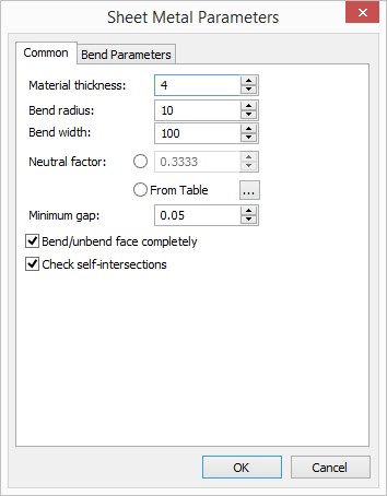
The parameter value can either be entered by the user or defined by the system automatically, based on the table of Neutral factors versus “bend radius/workpiece thickness” ratio. The definition is controlled by a radial-button switch. To use automatic Neutral factor definition, set the button “From Table”. Setting the other button allows entering an arbitrary number in the range from 0 to 1. The value “0” means the neutral layer coincides with the workpiece face selected for bending, while “1” sets the neutral layer on the opposite face of the workpiece.
The Neutral factor dependency table is stored with the model document. To view or edit the table, use the button ![]() . Upon pressing the button, an additional window “Neutral factors” opens up.
. Upon pressing the button, an additional window “Neutral factors” opens up.
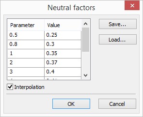
This window displays the Neutral factor table of the current document. It represents a tabulated dependency of Neutral factor (the column “Value”) on the ratio “bend radius/workpiece thickness” (the column “Parameter”). The flag “Interpolation” defines the type of interpolation of the table data: the set flag means linear interpolation – the Neutral factor linearly interpolated between the tabulated data; the cleared flag means piecewise constant interpolation – the Neutral factor is maintained constant until reaching the next entry.
The current table can be exported into a textual file by pressing the button [Save…].
The button [Load…] is provided for importing table data from an existing user-created text file “*.tnf” in the following format: the first line in the file defines the interpolation type: the keyword “Interpolation” means linear interpolation, “Table” – tabulated. Other lines contain the table data – the “bend radius/workpiece thickness” ratios and the respective Neutral factor values. The table data can be entered in an arbitrary way - in one line or in multiple lines, separated by spaces or tabs. For example, the default table file appears as follows:
Interpolation0.5 0.25
0.8 0.3
1 0.35
2 0.37
3 0.4
4 0.41
5 0.43
10 0.47
12 0.5
Once loaded from a file, the table is stored in the document of the current model and is further used in model manipulations.
Minimum gap. Define the width of a cut when creating operations with sheet metal.
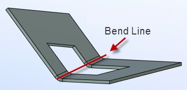
Bend/unbend face completely. This parameter is important when performing operations on the sheet metal of certain geometry (for example, when it is required to bend the sheet body with a cut along the specified line). When this parameter is enabled, the entire body along the selected line will be bent without violating the construction logic.
Check self-intersections. This parameter is important when creating the «Bend» parameter. It allows us to monitor self-intersection of bent sheet faces.
The «Bend parameters» tab
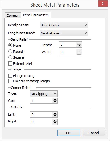
The parameter “Bend position” defines the position of the bended area with respect to the baseline of the bend: “Bend start”, “Bend center” or “Bend end”.
The way of defining the flange length is controlled by the parameter “Length measured”. The four values in the combo box are: “Neutral layer”, “External side”, “Internal side”, “Flat part”. Selecting one of them sets the desired default way of length calculation.
The group “Bend Relief” defines the type and dimensions of the reliefs created by default when bending:
The type of reliefs is defined by the radio group: “None” (no reliefs), “Round”, “Square”.
The parameters “depth” and “width” allow defining the default dimensions of a relief: the incision depth (length) ahead of the bend line, and the width of the relief slot.
Setting the flag “Extend relief” sets the mode of cutting the slot up to the borders of the workpiece.
The group “Flange” provides various options for default material trimming when making flanges. Gaps are introduced by reducing the flange dimensions when bending or attaching a flange, if directed by the flag “Flange cutting”. When the flag is set, gaps are introduced by default. The flag “Limit cut to flange length” controls the ways of material removal from the workpiece under the flange: when set, the material will be removed by the flange length (by default); when cleared – up to the borders of the workpiece.
The parameter “Corner relief” controls trimming of intersections between the attached flange and the workpiece faces. For trimming, select the option “On” in the combo box and enter the desired amount of Gap between the trimmed faces. If “Off” is set, the intersecting portions will not be trimmed.
The last group of parameters – “Offsets” – defines offsetting from the ends of the bend base line. The offset sides (“Left”, “Right”) are assigned by the system arbitrarily.
The parameters defined in the command “SMP: Sheet Metal Operation Defaults” will be used by default in all sheet metal handling commands. Those values will appear as “Default” in both text and numerical parameter entries. For numerical parameters, the actual value will be displayed next to the parameter input box.