Preparatory Operations for Handling Sheet Metal |
  
|
Preparatory Operations for Handling Sheet Metal |
|
Sheet metal commands facilitate modeling of parts made of forming sheet metal. Those help create an initial flat part (workpiece) of the specified thickness, and then perform various shape manipulations, such as bending about a selected line, attaching flanges to the workpiece, making punches. Once modeling is finalized, the part can be unbent to the unfolded pattern, as for the purpose of drafting, and then re-bent to the actual part shape.
The special "Forming Feature" command in the sheet metal group of commands helps creating various commonly used forming features, such as beads, ribs, flanges, louvers, pockets.
When working with sheet metal, you can use not only the specialized commands described in this chapter, but also general-purpose commands (Extrusion, Boolean operations, Hole and so on).
In addition, there is a capability of creating sheet bodies and bended sheet objects on the basis of 3D models with the help of the «Convert solid to sheet metal» operation and create sheet bodies based on two sections using Lofted Bend operation.
Note that the sheet metal operations do not account for possible material deformations. Rather, those are based purely on geometrical calculations.
Default Parameters for Sheet Metal
General sheet metal parameters
You can define common settings for the whole group of the sheet metal commands. Those determine the values of main parameters of the group operations:
● Metal thickness;
● Main bending parameters – the bending radius, the position of the neutral layer of plastic deformations, the shape and dimensions of the relief slots and some other parameters.
The specified settings will be used across all sheet metal commands in the case of using "Set as default" value. As general parameters change, the operations that use those will adjust their parameters.
Initial workpiece for sheet metal operations
Main concepts
All sheet metal operations manipulate with the initial preformed workpiece. The workpiece can be a solid body of virtually any shape. A system requirement for defining various sheet metal operations is existence of two flat parallel faces in the area of deformation. One of such faces will be used as the base when defining the desired type of a sheet metal operation. Additionally, the side faces of the workpiece that will be subjected to deformation during bending must be perpendicular to the base face.
We recommend using a flat body as the sheet metal workpiece, with the side (end) faces perpendicular to main (top and bottom) faces. Such body can be created, for instance, by the extrusion operation or by the special command for creating a sheet metal workpiece.
The special sheet metal workpiece creation operation is essentially an extrusion in the direction normal to a flat contour, to the specified depth. Use of this specialized operation instead of extrusion or other general-purpose operation simplifies workpiece creation, minimizing the number of parameters and settings to define.
This command serves to create a sheet body workpiece using one of two methods: by the defined shape of the workpiece or by the defined shape of the workpiece cross-section. Both methods use a flat 3D profile as the source.
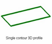
When creating a sheet workpiece by the defined workpiece shape, the source 3D profile defines the contour of the would-be workpiece.
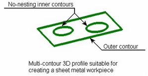
We recommend using a single-contour 3D profile. It is still possible to use a multi-contour profile, if it satisfies the following requirements: the 3D profile must have a single outer contour, and the inner contours with no nesting.
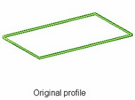
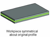
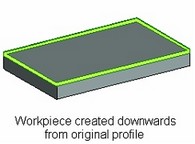
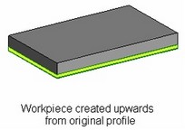
In this method of creating a sheet workpiece, besides the 3D profile, the thickness of the would-be workpiece and the direction of extruding its profile are defined at creation. The selected profile is extruded along the normal, to the specified depth equal to the width of the workpiece sheet metal. The extrusion is done in one of the three ways: upwards from the original profile, downwards from the original profile, or in both directions.
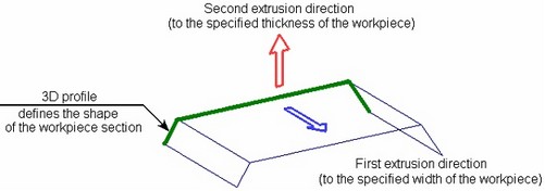
When creating a sheet workpiece by the workpiece cross-section shape, the 3D profile determines the shape of the workpiece body. In this case, only a flat single-contour 3D profile can be used. It can be closed (which will result in a “pipe”-type workpiece), or open.
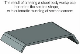
To create the workpiece, the selected 3D profile is extruded in two steps. First, the extrusion is made in the normal direction to the plane of the selected 3D profile to the specified width of the workpiece sheet. The edges of the resulting sheet body (the corners of the workpiece cross-section) are automatically rounded. This defines the shape of the would-be workpiece. Then, this sheet body is extruded normally upto the specified workpiece thickness. As in the previous case, extrusion by the sheet thickness can be done in three ways relative to the surface resulting from the first extrusion.
From now on throughout this chapter, any body subjected to a sheet metal operation will be referred to as "workpiece" regardless of the means of the body creation.