Top-down Design |
  
|
Top-down Design |
|
Design approach
There are two ways of designing a 3D assembly "top-down":
1. By saving already existing solid objects in a separate document.
2. By creating a new Part in the assembly mode.
The first approach allows using already existing solid geometry constructions that can be created by common modeling tools. Saving the body into a separate file can be done, for example, for delivering a set of drawing documentation of the Part. Alternatively, this can be done, if the model is intended for use in this or other assemblies as a 3D fragment.
The "top-down" design technique is quite effective when working with the part in the three-dimensional assembly mode – the second approach. In this mode, you can create new assembly components or modify the existing ones. A Part created in this way can have either associative or non-associative relation with the assembly.
The significant differentiator of the approach is as follows. When working in the assembly mode, you can outsource to the part file not only the assembly operations, but also arbitrary 3D construction elements, such as workplanes, 3D profiles, 3D paths, etc. This property is the main advantage of the assembly-mode design. Thus, for example, you can use assembly edges, 3D nodes or surfaces for defining directions, or use assembly faces, workplanes, etc. for defining the bounding conditions. When creating or editing a part, all system commands are available. You can also use objects already created in the assembly. You can shape up a part without unloading objects from the assembly. Instead, you can reference those as the base data for creating operations or 3D construction elements. In any case, use of assembly objects automatically provides attachment of the part to the assembly.
The "top-down" design approach may not be considered suitable for all cases of designing assemblies. It has a number of shortcomings that somewhat limit its use, such as follows:
●More cumbersome organization, as compared with the approach "from part to assembly";
●Weaker robustness to topological changes in the 3D model;
●Parts are less convenient when using the same 3D model in various assemblies;
●Higher usage of computational resources.
Particulars of creating and editing Parts
Before you start designing an assembly, you need to think through its composition. Decide, what parametric properties to build in one or another Part; what is the probability of introducing changes in the future, etc. You need to follow certain recommendations and keep in mind the specifics of the method used in order to achieve the best results in the initial design, as well as to leave open a provision for quick input of changes in the model.
Thus, try to restrict to the Part file most of the steps/operations necessary for building the model, while borrowing from the assembly only the unavoidable data for attaching the Part. This means, you shouldn't always rely on the opportunity of initially creating a most accurate "concept" of the Part directly in the assembly, with later unloading the resulting body of the would-be Part into a separate file. On the contrary, your design should preferably proceed in such a way, that the most of the Part 3D model structure could end up in the Part file. This can be achieved easier by creating the new Part in the assembly mode, when you need, for instance, just edges or faces of the assembly model for the part references and attachment. Following this recommendation will allow, in most cases, modifying the Part without referring to the assembly document. This is particularly important when the introduced changes should affect the Part 3D model structure as the order and composition of the modeling operations change upon adding or deleting operations.
As an example, consider the following diagrams:
The first two diagrams show the undesirable Part layout. As appears from the assembly structure, the operations were created first that defined the Part body. Those were followed by the operation Part created by unloading the resulted body (Boolean_4). If we try to edit such Part, we will find in its model tree only one external operation unloaded from the assembly. Therefore, to make changes to the original operations of the Part, we will have to load in the assembly. Upon modifying the assembly, we will have to start the procedure of updating the Part file. This order of steps does not promote productivity. However, if the engineer is assured that no changes will be required for the Part in the future, he can proceed with this technique.
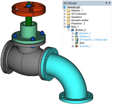
Let's consider another approach:
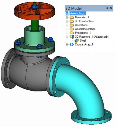
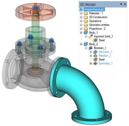
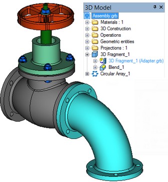
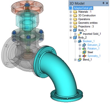
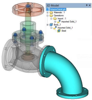
The above diagrams show the recommended approach to the Part creation. In this case, the Part is designed completely in the assembly mode. The flange of the body is used as the geometrical base for attaching the hose. As you can see in the diagram, all operations of the Part body creation are located in the Part file.
Continuing with this example, one can figure out the preferred techniques of introducing changes in the Part geometry. Let's consider a scenario, when we need to "refine" the existing Part by creating, for instance, an edge blend operation in this Part. A common mistake is blending the desired edge directly in the assembly, thus creating the blend operation on top of the operation Part. Proceeding in this way is undesirable, since the blend operation will not reflect on the Part file itself. Preferably, one should perform blending while editing the Part – either in the assembly mode or in a separate file.
|
|
Undesired layout |
Preferred layout |
Detail Creation
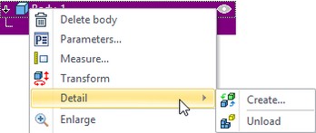
You can unload solid geometry in a separate file using the Create and Unload operations.
The commands can be activated in context menu in upon selecting any operation in the 3D window or in the 3D Model window.
Unload
Upon calling the Unload command, the system offers selecting the type of relation with the Part. The selection is done in the dialog box that comes up automatically:
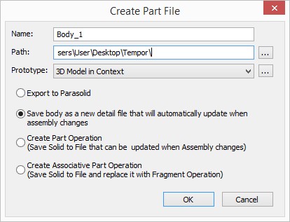
You can select a filename in the Name field.
You can select a directory for the file in the Path field.
Prototype. You can select a prototype for the part. The option allows you to select your own prototype with the required parameters.
●Export (Save Solid to File)
If the item “Export (Save Solid to File)” was selected the dialog for export of the detail in Parasolid format appears. The selected elements are saved in a separate file of Parasolid (*.x_t) format, that will no longer depend on the assembly drawing. The export operation in no way affects the assembly structure.
●Save body as a new detail file that will automatically update when assembly changes:
The model with its current geometry is unloaded to a separate GRB file.
An important feature of this method is ability to transfer all model changes from assembly to detail. Detail can be inserted as a fragment into other assemblies.
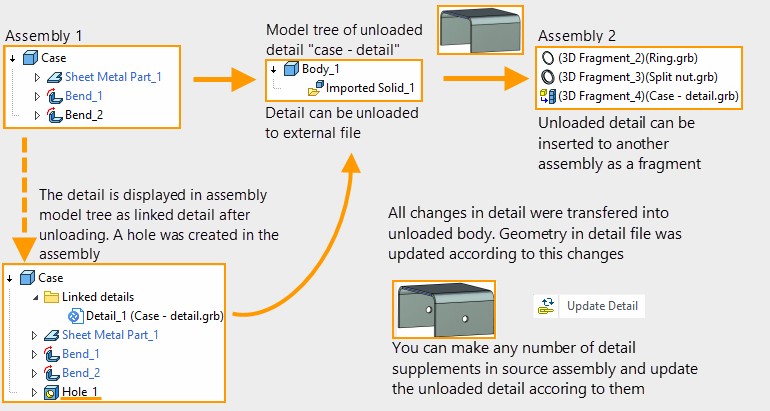
The history of detail creation is not unloaded from the Model Tree.
“Linked details” folder appears in the 3D Model window after the detail unloading. The folder includes all details that are unloaded for current body or fragment using the current type of relation.
Context menu:
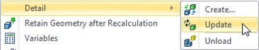
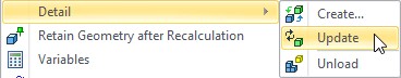
Update detail. Allows to update the unloaded detail according to the detail geometry changes in the assembly.
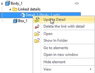
Delete the link with detail. Allows to delete link with the unloaded detail. The detail will not be linked with the assembly and its update will be unavailable.
Open. Allows to open the detail file.
Show in folder. Shows the detail file in Windows explorer.
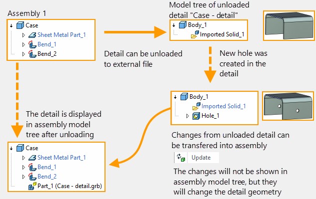
●Create Part Operation (Save Solid to File that can be updated when Assembly changes):
The model with its current geometry is unloaded to a separate GRB file.
Detail can be updated when geometry of unloaded operations is changed in the assembly file. However, the operations that were created after detail unloading will not be transferred to detail.
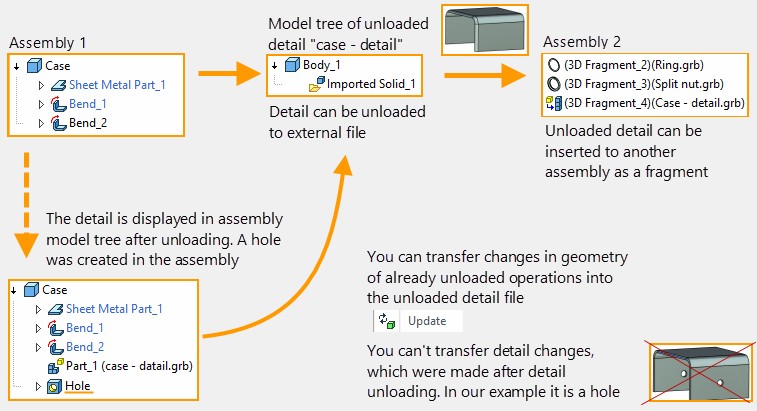
You need to select Detail > Update from the detail context menu to update the detail according to its geometry changes in the assembly. You can update detail according to the changes in already unloaded geometry.
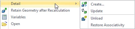
Restore Associativity. The option allows to unload changes in the detail file into the assembly. Note that errors may occur if there were changes in the detail geometry in the assembly.
For example, a hole was created in the assembly after the detail unloading, and blend was applied in the detail file. There will be an error because the face for the hole creation was changed.
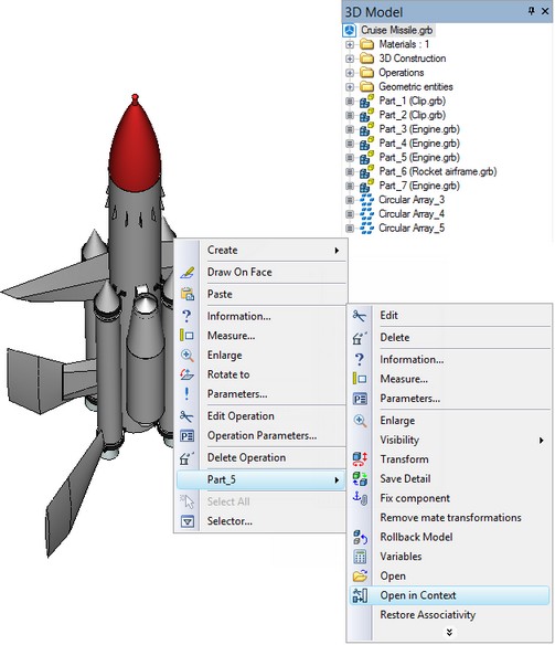
●Create Associative Part Operation (Save Solid to File and replace it with Fragment Operation):
The model with its current geometry is unloaded to a separate GRB file. Meanwhile, the part itself is inserted back into the assembly, using the 3D fragment technique.
This establishes two-directional relation between the assembly and the part file.
It allows system to update the geometry in the assembly file, if there were any changes in detail. In this case, the detail plays the same role, as the 3D fragment, with the difference that the original data for the detail exists in the assembly document.
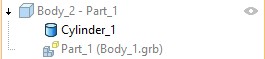
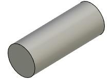
Moreover, you can rollback model to the moment of detail unloading and change the detail geometry.
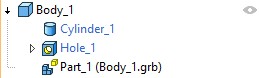
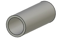
A cylinder body was created in the assembly and unloaded as a detail. Then the rollback to the moment before unloading was performed in the assembly. Rollback model option from the context menu Cylinder was used for this purpose.
|
|
After the rollback, a hole was created and the rollback was finished.
|
|
After finishing of the rollback, you can update the detail and all changes will appear in the detail file.
Create
If the original file of a parametric 3D fragment or Detai differs from its instance currently used in the assembly due to changes in the variables, you may want to save the latter instance in a separate file. This may be necessary, for instance, in order to file a new set of documentation reflecting the current modification. The detail operation creates a new copy of the 3D fragment or body in separate file that can be saved under a different name.
If drawings existed in fragment file that was unloaded as a detail, they will be updated according to the fragment file changes in the assembly.
You can unload a detail using one of the following ways:
In the first case the new detail copy does not have any relation with the assembly. It merely provides the user with a modification of the part recalculated with certain variable values and written to a separate file.
In the second case, fragment, Detail or body in the assembly can be replaced with the unloaded detail. It is important that after this replacement it is possible to transfer all changes from the assembly to the detail.
Command Options
The detail creation command is launched from the context menu corresponding to the selected operation of the 3D fragment, Detail or body, whose detail we want to create.
![]()
When performing it, a dialog appears, in which you need to specify the name of the document being created and whether it is required to save it immediately to a file. You can specify derictory for the file.
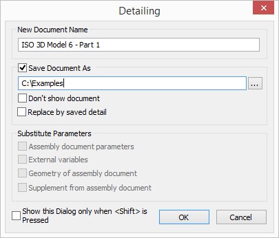
New Document Name. You can specify name for the detail document.
Save Document As. If the flag is not set, the detail file will be opened in T-FLEX CAD, but it will not be saved. It allows to preview the detail.
Don’t show document. If the flag is not set, the detail file will be opend in T-FLEX CAD after saving.
Replace by saved detail. If the flag is set the unloaded detail will be linked with the assembly. It allows to update the detail according to the changes in the assembly.
To update the detail use update option from the context menu of the detail in the assembly.
The unloaded detail is a fragment and all its changes can be unloaded to the assembly.
Assembly document parameters. When the option is set all assembly parameters from ST: Document parameters command are transfered to the assembly.
External variables. When the option is active all variables from the assembly document are unloaded to the detail
Geometry of assembly document. The option is used for fragments in context and adaptive fragments. It allows to unload geometry based on which the fragment was created.
For example adaptive fragment was inserted into the assembly. If geometry on the basis of which the fragment was created has changed and the changes can be unloaded to the detail. If the flag is not set, the detail will be created based on the geometry which had existed at the time of inserting the adaptive fragment.
Supplement from assembly document. Allows to unload supplements of the fragment or body from the assembly.
For example, a fragment was added to the assembly. A hole was created in the fragment. The supplement option was enabled upon the hole creation. The supplement can be unloaded to the detail with the fragment.
Working in the assembly mode (assembly context). Creating a Part
To create a new Part in the assembly mode, call the following command from the File menu:
Icon |
Ribbon |
|---|---|
|
Assembly → Assembly → Fragment in context → Create |
Keyboard |
Textual Menu |
<FM> |
File > Fragment > Create |
Immediately after calling the command, the system asks the file name for the new Part. The assembly mode turns on thereafter, with all assembly operations becoming transparent. All assembly objects - faces, vertices, 3D construction elements and operations - remain available for selection. From now on, anything created by the usual tools will belong to the Part file.
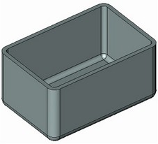
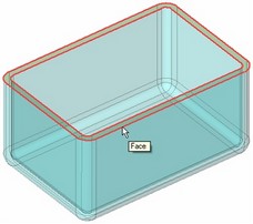
Suppose, we need to create a top for a box part. To do this, let's call the detail creation command and select the top-end face.
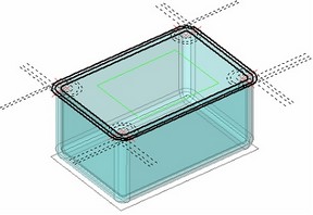
This gives us access to the 2D drafting commands. Create the necessary graphic elements for the 3D profile that will be used for the top creation. Do all steps in the same order as in conventional drafting on the active workplane.
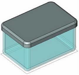
Upon extruding the profile and rounding the edges, we get the ready model of the top.
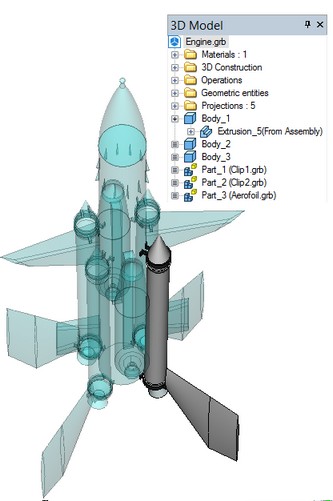
The 3D model tree displays the structure of the Part model. All elements that were unloaded from the assembly model are labeled "(From Assembly)".
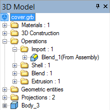
The label that marks in the model tree the elements unloaded from the assembly is appended only when editing the Part in the assembly mode. If you open the Part file separately for editing, then the elements unloaded from the assembly will appear in the model structure merely as the external imported models.
Sometimes, the operations unloaded from the assembly model into the Part do not need to be displayed in the 3D window. Therefore, those can be hidden by specifying an invisible level for them. In such a case, those will not contribute to the Part mass properties either.
Editing can be finished at any moment either with saving the Part file or by rejecting the changes done since the last Part save. The commands for returning to the assembly document can be accessed in the context menu by right clicking in the 3D window.
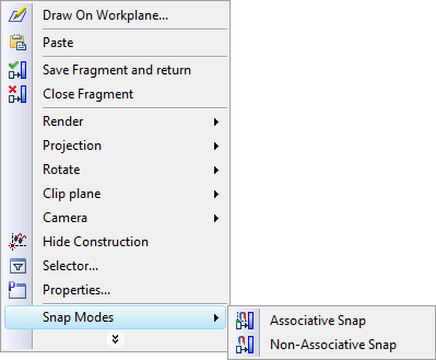
The same context menu contains another item with two unfolding sub-items for controlling the attachment mode to the assembly elements. The attachment can be by associative or non-associative snap. When creating Part elements in the associative attachment mode, the relation is maintained with the assembly objects. This mode allows propagating any changes from the assembly geometry in the Part model. In the non-associative attachment mode, any assembly object reference is replaced by a non-associative copy of the assembly object, realized as in external operation. This external operation is in no way related to the assembly model. If you don't want this copy to appear in the assembly, hide it by assigning, for instance, an appropriate visibility level.
It is also possible to undo any attachments to the assembly elements, while maintaining the object snapping only to the Part file elements. To turn off any mode of attaching to the assembly elements, you need to pick once again the item of the turned on mode in the context menu in order to undo the snapping.
Generally speaking, you can work with a 3D fragment in the assembly model as well as with a Part file. To start editing in the assembly mode, call the command "Edit" from the context menu invoked over the operation "Part" or "3D fragment".
When editing a 3D fragment in the assembly mode, you can use the assembly elements as references just like when creating/editing a Part. This will not convert the edited "3D Fragment" operation into the "Part", rather, some Part properties will be attributed to the fragment. Thus, for example, use of configurations will be banned, and dependency on the assembly geometry won't be supported. (You need to remember this in order to avoid recursive dependencies.)
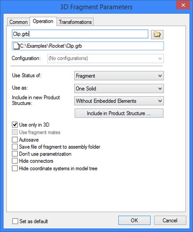
Part properties
The operation "Part" possesses mostly the same parameters as the operation "3D Fragment". In fact, it is a 3D fragment, too, however created by different means. The only item not accessible in the "Operation" tab will be the configuration selection field, as the use of configurations is not allowed for Parts. (Use of configurations is described below.)
If the Part is expected to appear in BOMs, define the necessary data in the same way as for a 3D fragment.
Part transformations are done in the same way as for any other operation that is not using coordinate systems for attachment. For detailed information on this, you can refer to the chapter "Transformation".
Relation between assembly and Part file
Part file path references are made by the same rules as those of the 3D fragments (see above).
The type of relation between the Part and the assembly is established at the time of the Part creation. As was mentioned earlier, changes can be propagated from the assembly to the Part or vice versa, depending on the relation type. The system would repeatedly unload the original data into the Part file only when forced by the user. All Part files can be updated by the command:
Icon |
Ribbon |
|---|---|
|
Assembly → Assembly → Fragment in context → Refresh Files |
Keyboard |
Textual Menu |
<FG> |
File > Fragment > Refresh Files |
To update just one selected Part file, call the command "Update". This command is available in the context menu upon right clicking over the Part.
If the reverse relation is established between the Part and the assembly (as in the case of a 3D fragment), then the system tracks changes in the Part files automatically. Everything works as if with 3D fragments. If you need to force reloading of all modified Parts into the assembly, call the command:
Icon |
Ribbon |
|---|---|
|
Assembly → Move Assembly → Component links → Update Links |
Keyboard |
Textual Menu |
<UL> |
File > Assembly > Update Links |
Reloading the data from one specific Part into the assembly can be done by the context menu command "Update".