Editing Graphic Lines |
  
|
Editing Graphic Lines |
|
Editing graphic lines is done by the command "EG: Edit Graphic Line". Call the command via:
Keyboard |
Textual Menu |
Icon |
<EG> |
"Edit|Draw|Graphics" |
|
The following options become available upon calling the command:
![]() <*> Select All Elements
<*> Select All Elements
![]() <R> Select element from list
<R> Select element from list
![]() <Esc> Exit command
<Esc> Exit command
When in the command, one can select a graphic line entity by pointing the cursor and clicking ![]() . Several graphic lines can be simultaneously selected by box. The graphic lines will be selected that are completely within the box.
. Several graphic lines can be simultaneously selected by box. The graphic lines will be selected that are completely within the box.
All graphic lines can be selected at once by typing <*>. To add a graphic line to the set of already selected ones, use the combination <Shift> +![]() . To exclude a graphic line from the selected set, use <Ctrl>+
. To exclude a graphic line from the selected set, use <Ctrl>+![]() .
.
The following options become available after selecting one or several graphic lines:
|
<P> |
Set selected Element(s) Parameters |
|
<Alt+P> |
Copy Properties from Existing Element |
|
<I> |
Select Other Element |
|
<Del> |
Delete selected Element(s) |
|
<Esc> |
Cancel selection |
If only one graphic line is selected, then the following option is available:
|
<O> |
Create Name for selected Element |
If a graphic arc entity is selected, the following additional options become available in the automenu:
|
<Tab> |
Change arc direction |
|
<A> |
Link Arc or Circle to Node |
|
<B> |
Break Link with Node |
If the selected graphic line is created based on a construction line, then Relations for the parent construction line will appear in the 2D window. Those relations are temporary, meaning that those are created by the system automatically upon entering the mode of editing a graphic line, and are automatically deleted upon exiting the mode. Using Relations, you can modify geometrical parameters of the parent construction line in the transparent mode.
Besides that, if the selected graphic line is created based on a construction line, then the second click ![]() after selecting the line (while the cursor is pointing at the line) will invoke the command of editing the original construction line.
after selecting the line (while the cursor is pointing at the line) will invoke the command of editing the original construction line.
To modify parameters of the selected graphic line, use the option ![]() . The initial parameters are taken from the last selected graphic line.
. The initial parameters are taken from the last selected graphic line.
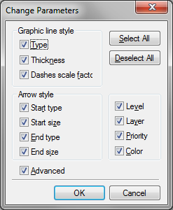
If the user needs to bring the parameters of a graphic line in accord with a given line parameters, then the latter should be selected the last before proceeding with the modifications. This will automatically pre-set the desired parameters in the dialog. If more than one graphic line is selected then another dialog box comes on the screen before the parameters dialog box. Its purpose is to define what parameters of the selected graphic lines are to be modified.
After that, the graphic line parameters dialog box will appear. Now, only the parameters will be modifyable that were specified in the previous dialog box. For instance, if in the previous dialog only the line type was checkmarked for modification, then only this parameter can be modified. Other parameter modifications will be discarded.
Object properties can be also set from another object (including image line) in command waiting mode with the help of the Properties window. See more details in "Main Concepts of System Operation" chapter.
The current set of graphic line parameters defined during the editing can be saved. New graphic line creation would then be based on this particular set of parameters.
To open the parameters dialog box for a single graphic line, one can simply double-click it (![]()
![]() ).
).
The option ![]() is used for assigning a name to the selected graphic line. The name is unique and provides unambiguous identification to the line. The graphic line name can be used instead of its Id number. For example, the function GET() can be used in the variable editor to query a graphic line, named NAME, as follows: GET("NAME", "LENGTH").
is used for assigning a name to the selected graphic line. The name is unique and provides unambiguous identification to the line. The graphic line name can be used instead of its Id number. For example, the function GET() can be used in the variable editor to query a graphic line, named NAME, as follows: GET("NAME", "LENGTH").
The option ![]() allows flipping the direction of graphic arc entity creation.
allows flipping the direction of graphic arc entity creation.
The following options are available in the automenu for graphic arc entities, ![]() and
and ![]() . These options manage a locking node of graphic arcs constructed on top of a construction entity. Throughout modifications of the drawing, the graphic arc will stay over the sector of the underlying construction circle that is closer to the locking node.
. These options manage a locking node of graphic arcs constructed on top of a construction entity. Throughout modifications of the drawing, the graphic arc will stay over the sector of the underlying construction circle that is closer to the locking node.
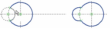
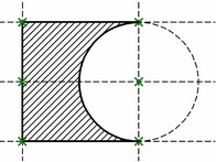
Let's review the following example. When moving one of the original lines, the part is supposed to get mirrored. However, the graphic arc will stay in its original orientation as the vertical line is moved, resulting in the wrong final shape of the part. This can be fixed by using a locking node.

To keep the arc always in the correct sector of the circle, link it to a node. After calling the command "EG: Edit Graphic Line" select the arc and use the option ![]() . The cursor will change to "finger"
. The cursor will change to "finger" ![]() . Then, select the locking node using
. Then, select the locking node using ![]() .
.
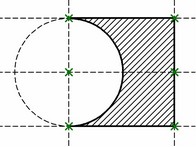
Now, as the vertical line is moved, the whole drawing will be flipping, maintaining the original relative configuration.
To release the link with the node, use the option ![]() .
.
To cancel the last graphic line selection and select the next nearest graphic line to the current cursor position, use the option ![]() . This option is convenient when there are several closely located or overlapping graphic lines, and the first selection attempt yielded the wrong graphic line.
. This option is convenient when there are several closely located or overlapping graphic lines, and the first selection attempt yielded the wrong graphic line.
The option ![]() deletes all selected graphic lines. The option
deletes all selected graphic lines. The option ![]() cancels the current selection of graphic lines.
cancels the current selection of graphic lines.
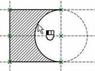
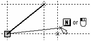
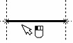
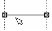
Besides, a capability is provided for reassigning the start and end nodes of the graphic line. Reassigning the nodes is possible for a single selected graphic line. Once the line is selected, the nodes get highlighted. Now, you can move the cursor over one of the highlighted nodes and click it ![]() .
.


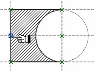
The line will then start rubberbanding after the cursor, with another option becoming available:
![]() <N> Select existing Node as the start or end of the graphic line
<N> Select existing Node as the start or end of the graphic line
You can select a node for the graphic line to snap to.
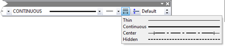
To change parameters of the selected graphic line, it is also convenient to use the system toolbar. With the help of it you can change the color, type, thickness and line ends.
For example, to change the line type with the help of the system toolbar – select the graphic line.
Move the cursor to the line type input box on the system toolbar ![]() and click
and click ![]() . A menu of line types will appear on the screen. Select a new line type by
. A menu of line types will appear on the screen. Select a new line type by ![]() . As the result, the appearance of the graphic line will change.
. As the result, the appearance of the graphic line will change.
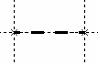
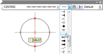
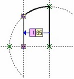
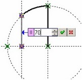
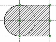
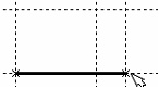
The graphic line endings can also be modified in a similar way. Use of endings is important, for instance, when applying centerlines. These are drawn in a dash-dotted style. To create centerlines with hanging extents, you would not need to create additional nodes beyond the circle (as shown on the diagram). Rather, select the start and end types of the graphic line as shown on the diagram. The size of the extents can be defined explicitly in the parameters of the graphic line, or left as [Default]. In the latter case, the size will be defined by the parameters in the command "ST: Set Document Parameters" (the tab Font, Size entry).
The same can be done easier. While in the command "G: Create Graphic Line" or "EG: Edit Graphic Line", press the graphic button ![]() on the right-hand side of the system toolbar. The list of the most often used lines with extents will appear.
on the right-hand side of the system toolbar. The list of the most often used lines with extents will appear.