Model Animation Command |
  
|
Model Animation Command |
|
Animating model by command "Animate Model"
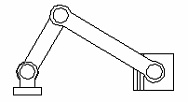
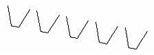
Drawing animation is implemented by a step-by-step modification to some parameter defined by a variable. The drawing is simultaneously redrawn at each step. Suppose, we have created a drawing of a kinematic mechanism. The drawing is assembled from fragments, each of which is a link in the mechanism. Now, we would like to view the behavior of the mechanism as the position of the driving link is varied. |
|
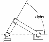
The driving link position is defined by the parameter of a construction line defined as a line passing through a node at an angle to the horizontal. This parameter is the angle of rotation. One can assign a variable to drive this parameter. Let's call it "alpha".
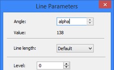
To "animate" the mechanism, use the command "AN: Animate Model":
Icon |
Ribbon |
|---|---|
|
Tools → Animation → Animate |
Keyboard |
Textual Menu |
<AN> |
Parameters > Animate |
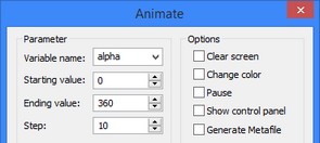
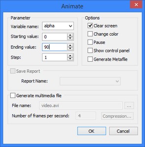
When entering the command from the 2D window, a dialog box with the command parameters is displayed on the screen. The parameters are as follows:
Variable name. You can specify the name of the variable whose value will change. The variable’s name can be specified manually or selected from the suggested list. All real variables of the drawing are included in this list. The variable cannot be a text variable.
Starting value. This is the starting value of the variable to vary.
Ending value. The target value of the variable at the completion of the command.
Step. The increment value added to the variable at each step of the animation.
Clear screen. With this option set, the screen will be redrawn at each step. Otherwise, the images will be overlapping to show the progress of the movement and drawing modifications at each step.
Change color. With this option set, the image at each step will be displayed in its own color. This option is useful when you want to compare results when varying the values of different drawing parameters.
Pause. With this option set, the system will require confirmation at each step, before drawing another frame.
Generate Metafile. With this option set, the animation clip will be saved in a T-FLEX CAD metafile. This metafile can later be output to a printer or plotter, included in a T-FLEX drawing using the command "IP: Insert Picture" or exported into another format. Note, that with the "Clear screen" mode turned on, a metafile will not be output.
Save Report. With this option set, the result of animation at each step will be output in a log file (the filename must be specified in the operation parameters). This parameter is available only when the model has at least one report template, defined in the command "REP: Create Report".
Generate multimedia file. Setting this option allows creating an *.avi file and defining its parameters:
File name.
Number of frames per second. The recommended frequency is 24 frames per second.
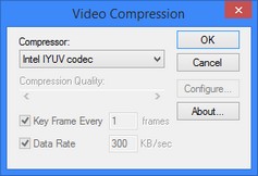
The graphic button [Compression…] invokes the dialog box for customizing multimedia file compression parameters:
Compressor. Selects a compressing application. Compression Quality. Defines the quality grade for multimedia file compression. Key Frame. Defines the number of frames between the key frames. Data Rate. Defines the data transfer rate (kilobytes per second). The graphic button [Configure…] brings up the dialog box for entering the required settings of the selected compressing application. |
|
To interrupt a running animation, press <Esc>. Returning to the above example, let's define the first four parameters. The specified values realize the variation of the "alpha" variable from the value "0" to "360" with the step equal to "10". The drawing will be displayed at each step. |
|
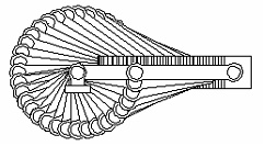
Press [OK], and the result shown on the right hand side diagram will soon be displayed on the screen. By performing these steps on your computer, you will see the drawing "animate". Consider a few more examples. In those, several variables are made dependent on the driving variable, which results in an interesting behavior.
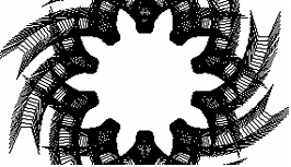
An animation of the drawing of a cutting tool appears as if "machining" of a cog wheel:
Next is the example of a drawing that creates a function diagram by using animation.
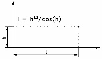
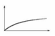
What was entered in the variable editor is as follows: the variable "h" is equal to "10", and the variable "l" is defined by the expression "^1.2/Cos(h)".
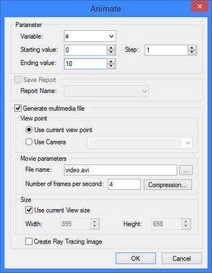
Note, that when calling the command "AN: Animate Model" while in the 3D window, the animation parameters dialog box has a slightly different appearance. In this case, to create a multimedia file, one needs to define the following groups of parameters:
Size. Defines the window size of the image being saved.
Use current View size. With the flag turned on, the whole contents of the current 3D view window are recorded. With the flag off, the user can define one's own width and height parameters of the image being saved.
View point. Defines the position and direction of the animation recording camera.
Use current view point. The view point is defined by the system camera present in any 3D window by default.
Use camera. The other possibility is specifying a user-defined camera.
Create Ray Tracing Image. With this flag turned on, each animation frame is processed by the application POV-RAY, that makes a realistic image, accounting for the material, light sources, etc. Creating a realistic image increases the recording time of the AVI file, while considerably enhancing the appearance.