Extending Surfaces |
  
|
Extending Surfaces |
|
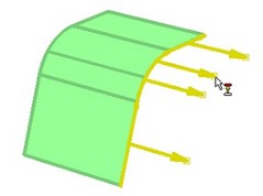
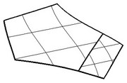
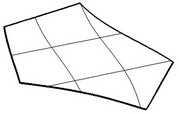
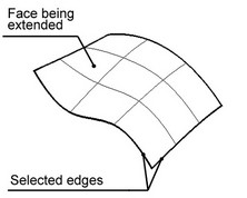
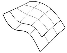
This command allows extending a selected face (or several faces belonging to a sheet body) in the specified direction, for the specified length amount. The direction of extending the face is defined by selecting the side edges of the faces being extended. 3D profiles can be extended as well. In this way, an enlarged face will be created as a result of executing the command, identical in shape with the underlying surface of the 3D profile.
Sometimes, self-intersections occur when extending a face. In such cases, the command execution ends up in an error message.
Using the command
The command "3SX: Surface Extend" can be called from the textual menu:
Icon |
Ribbon |
|---|---|
|
3D Model → Special → Faces → Extend Faces |
Keyboard |
Textual Menu |
<3SX> |
Operation > Face > Extend Faces |
To use the command, do the following sequence of steps:
1. Select the object to extend.
2. Select edges.
3. Specify extension amount.
4. Define advanced parameters (optional).
5. Confirm operation creation.
Selecting object to extend
To select an object to extend, use the option:
![]() <R> Select surface operation
<R> Select surface operation
When specifying an object to extend, you can select faces, 3D profiles and sheet bodies.
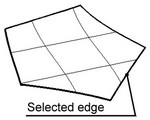
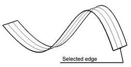
Selecting edges
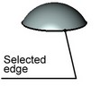
Once the object to extend is selected, you can select one or several edges bounding this object. Those edges will indicate the direction of extending the given object. To select edges, use the option:
![]() <H> Select Edge
<H> Select Edge
The default option for selecting edges is:
![]() <S> Smooth edge chain selection mode
<S> Smooth edge chain selection mode
To select individual edges, turn off this option.
To select all edges surrounding the selected object, at once, you can use the option:
![]() <A> Select all edges
<A> Select all edges
To cancel selection of any of the edges, click it again.
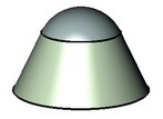
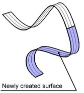
Defining amount of face extension
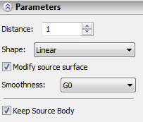
The entry "Distance" means the distance from the selected edge to the new edge bounding the extended surface, as measured along the surface.
Enter the amount of face extension in the "Distance" input box of the property window. Besides the property window, this value can be modified in the 3D window, using arrow-shaped draggers. The draggers appear after selecting at least one edge. To "grab" a dragger, move the pointer to the tip of the arrow (the pointer will then change its appearance) and depress the left mouse button. Note that the same extension amount is applied in all specified directions. |
|
Defining the advanced parameters
The parameter "Modify source surface" tells the system, whether to modify the original face topology, or leave it as is. The effect of this parameter on the result is shown below.
![]()
Original model |
"Modify source surface" parameter is off |
"Modify source surface" is on |
The parameter "Keep source solid" specifies, whether to leave the source body in the 3D scene (the whole body altogether, rather than just the selected face). If this parameter is off, the source body disappears upon the operation completion. The parameter "Shape" defines the shape of the new face created as a result of executing the command. This parameter can take several values.
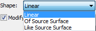
"Linear" means, the face extends straight, staying tangent to the original face at each point of the selected edge. In this way, the surface curvature has a jerk near the selected edge. With the parameter value set to "Of Source Surface", most of the newly created surface is linear (ruled), as in the previous case. However, the surface curvature around the selected edge changes smoothly.
Original model |
|
"Of Source Surface" Shape |
"Like Source Surface" Shape |
In real life, the angular difference between the new surface with the parameter "Linear" and that with the parameter "Of Source Surface" is about 3 degrees. Therefore, the difference between the two results is practically vanishing.
The parameter "Like Source Surface" means the new surface will rely on the definition of the source surface. The example below shows the effect of this parameter on a spline surface.
Original model |
Resulting model |
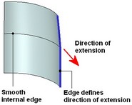
Original faces may contain internal smooth edges. Internal edge is considered to be “smooth” when converging faces that form this edge are tangent to each other at the point of intersection of the edge with another edge that defines direction of surface extension. The “smooth” state of internal edges may be affected in the process of surface extension. To avoid this set “G1” mode for “Smoothness” option (G1 - is geometric continuity by first derivative). This option will recommend system to retain tangent continuity, keeping “smooth” state of the internal edge on surface extension. By default “Smoothness” option is set as “GO” (recommendation to ensure only surface continuity).