Fill Hole |
  
|
Fill Hole |
|
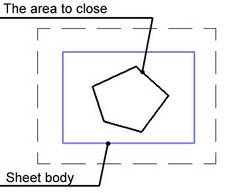
This command serves to patch “hole” contours (regions) in a sheet body. Filling is done by creating one or several faces closing the selected regions.
It is also possible to patch regions in a solid body, however with numerous restrictions.
The command is used in surface and solid modeling. It can also be useful when working with imported models whose bodies contain voids resulting from loss of faces due to export/import deficiencies.
When executing the command, the system may fill the gap using an analytical or ruled surface, depending on the original geometry. It is also possible to make patches based on a specified sheet body or geometrical surface.
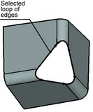
Selecting regions to fill
You can close several regions of one body at once by performing the operation.
Each region is defined by its contour - the set of edges making up the given contour. To define a contour, you need to specify all body edges that belong to it. Contours must be closed.
When defining contours, you can use the mode of automatic selection of all edges. In this mode, you just need to select one of the edges in each contour. The system will select the remaining edges automatically. The composition of the selected contours can then be manually edited.
An also provided mode to select all contours serves to automatically select all holes to patch in the specified body.
Hole-filling methods
The specified regions of a sheet body can be patched by various methods:
- Automatic generation of the filling surface;
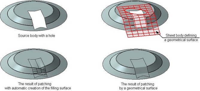
- Fill by the sheet body;
- Filling by a geometrical surface.
The surface resulting from patching regions is by default merged into the source body. If necessary, it can be saved as a stand-alone operation.
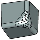
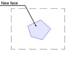
Filling with automatic patch surface generation
In this way of patching, the system automatically creates the faces that can close the selected body regions.
The user has a way to influence the type of the created faces. This is done by defining a preferred form of the closing surface:
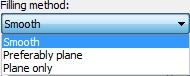
- Smooth – the system will attempt to create an analytical or ruled surface closing the selected region;
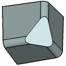
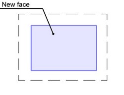
- Preferably plane – the application attempts to close the selected region with a plane first, and then, in the case of a failure, with a spline surface;
- Plane only – the system attempts to fill the region using only a plane. If this attempt fails, the command execution ends up with an error message.
Original model |
"Smooth" Filling |
"Preferably plane" Filling |
The preferred form of the filling surface is defined separately for each selected contour (that is, separate for each region to be patched).
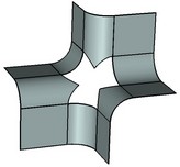
By default, the faces filling the area approach the original model smoothly (tangentially) at each edge bounding the area to fill. The smooth edge condition can be disabled for each individual edge or for all edges in a contour.
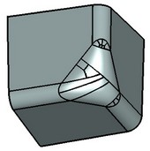
When closing a region with a ruled surface, there is an option to minimize the topology. In this case, the system will attempt, whenever possible, to close the gap with a minimum number of faces.
"Minimize topology" flag is off |
"Minimize topology" flag is on |
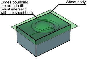
Fill by sheet body
In this filling method, an additional sheet body shall be defined. The selected regions of the source body will be closed based on it. Please note that in this case the same filling method is applied to all selected contours of the source body.
The sheet body defined as the filling surface must satisfy the following conditions:
- Fully close all holes being patched;
- Have only one boundary (for example, a sheet body like a side surface of a cylinder does not satisfy this condition);
- Not have holes.
Filling regions by a sheet body can be done in two ways.
The first method is filling with trimming by the borders of the patched regions. In this case, the system trims the shape-defining sheet body along the boundaries of the patched regions. The resulting surface is the sought filling surface. This filling method can be used only under the condition that the filling sheet body goes through all edges that surround the regions to be patched.
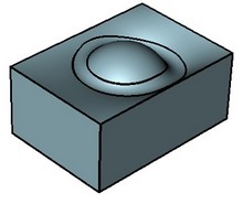
Original body |
Result |
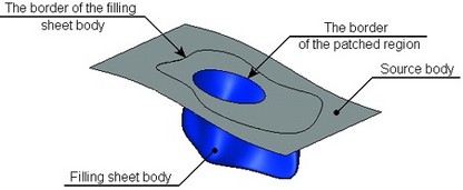
The second method is filling with trimming by the sheet body boundaries. In this case, a region is cut from the source body along the boundary of the filling sheet body. The filling sheet body then "patches" the cut region. That means, the entire sheet body is used as the filling patch. The necessary condition to use this method is that all border edges of the sheet body lie on the source body.
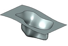
|
Result |
Shown below are schematic diagrams that demonstrate the difference between these two methods.
Original model |
Filling with trimming by the patched region borders |
Filling with trimming by the sheet body borders |
Filling by a geometrical surface
In this filling method, a geometrical surface is additionally defined, based on which the selected regions of the source body will be patched. The surface is defined by selecting a 3D object of an appropriate type (a worksurface or workplane, a face-underlying surface, a planar edge, etc.).
In this case, as in the previous one, the same filling method is applied to all selected contours of the source body.
The surface defined as the filling specimen must close all regions to patch in the source body. At the same time, you need to pay attention to the type of the selected surface. Some types of simple surfaces can be extended by the system beyond its defining element. For example, if a plane underlying a flat face was selected as the filling surface, then the system can extend this surface up to the infinity, and it will be always closing all selected regions. On the other hand, a surface beneath a spline face is strictly limited to the face borders.
Besides that, to successfully fill the gaps, the borders of all regions being patched must lie on the selected surface.
When patching, the system constructs a sheet body by the specified surface and trims it by the borders of the regions to be patched. The resulting body will be the filling one.
Specifics of working with solid bodies
The region-filling command allows processing holes in solid bodies as well. However, in this case the command capabilities are limited.
When patching the surface of holes in a solid body, only the “Filling by a geometrical surface” method can be used. You cannot use filling by a sheet body. In the cases when the surface is not specified, but the system managed to perform filling on its base, the system will automatically find the methods of closing this surface (you cannot specify it, unlike the case of the sheet body). Besides that, the result of filling a region in a solid body is always created as a stand-alone body (a separate operation). It cannot be merged with the source body.
Please note that the face - filling operation cannot be used to remove holes in solid bodies. The “Delete Faces” operation is instead used for this purpose.
Defining the operation
The command “3ZF: Fill Hole” can be called as follows:
Icon |
Ribbon |
|---|---|
|
3D Model → Special → Faces → Fill Hole |
Keyboard |
Textual Menu |
<3ZF> |
Operation > Face > Fill Hole |
To use the command, do the following sequence of steps:
1. Select the areas to fill.
2. Select the filling method by specifying the preferred form of the filling surface or a filling surface itself (a sheet body or a geometrical surface).
3. Define additional parameters for the selected filling method (optional).
4. Confirm operation creation.
Selecting regions to patch
Upon launching the command, the option to select contours of the regions to be patched is active by default in the automenu:
![]() <C> Select Contour
<C> Select Contour
The additional option is turned on by default:
![]() <G> Contour selection mode
<G> Contour selection mode
This option serves to create a new contour and select all edges belonging to it by picking just one edge.
If the ![]() option is enabled, then you just need to select one of its member edges in the 3D window in order to have the contour selected. The system will automatically find the remaining edges of this contour and make them selected. After that, you can right away proceed with selecting an edge of another contour, and so on.
option is enabled, then you just need to select one of its member edges in the 3D window in order to have the contour selected. The system will automatically find the remaining edges of this contour and make them selected. After that, you can right away proceed with selecting an edge of another contour, and so on.
The selected contours are entered in the “Contours” list in the properties window. If you select one of the contours in the list (by picking it with ![]() ), then the “Edges” field will display the list of edges that make up this contour. To manually select contour edges (this may be required, for example, when working with a solid body), disable the option
), then the “Edges” field will display the list of edges that make up this contour. To manually select contour edges (this may be required, for example, when working with a solid body), disable the option ![]() . In this mode, selecting an edge with the option
. In this mode, selecting an edge with the option ![]() will create a new contour in the list of contours (with a single selected edge). You can then select more edges for the contour using the option:
will create a new contour in the list of contours (with a single selected edge). You can then select more edges for the contour using the option:
![]() <E> Select Edge
<E> Select Edge
To define a second contour, you need to use the ![]() option again, create a new contour with a single edge in it, and then select more edges using the option
option again, create a new contour with a single edge in it, and then select more edges using the option ![]() , and so on.
, and so on.
To delete one of the defined contours, select it in the “Contours” list in the properties window, and then click the button ![]() beside this list.
beside this list.
To delete an individual edge in a contour, select the intended contour in the list of contours. The “Edges” list will display the edges of that contour. Select the desired edge and click the button ![]() beside the list of edges. The selected edge will be removed.
beside the list of edges. The selected edge will be removed.
To automatically select all holes in a sheet body as the contours to patch, use the option:
![]() <A> Select all Contours
<A> Select all Contours
After calling this option, you just need to select the sheet body, in which you want to close the holes. All contours will be defined automatically.
Defining parameters when filling with automatic generation of the patch surface
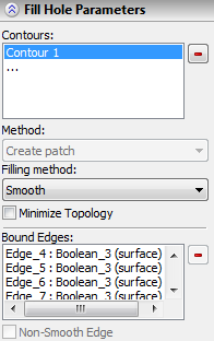
The preferred form of the patch surface is defined in the “Filling” field of the properties window. Please note that defining a preferred filling form of the patch surface is done individually for each selected contour. That means, in the case of selecting multiple contours, you need to pick each contour in the list in a sequence and define the preferred surface form for each of them.
When creating a continuous patch surface for all edges of all contours, the smoothness condition is set by default. To disable this condition for an individual edge, select the contour in the list of contours, which includes the given edge, and then select the desired edge in the list of edges of that contour. Set the “Non-smooth edge” flag for the selected edge. You can similarly reenable the smoothness condition for an individual edge of a contour, by selecting this edge and disabling the flag “Non-smooth edge”.
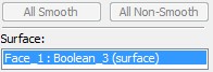
To disable the smoothness condition for all edges of all contours, you just need to click the button [All Non-Smooth]. The button [All Smooth] allows to reenable the smoothness condition for all edges of all contours.
The minimal topology mode is enabled by setting the flag “Minimize Topology” – separately for each patched contour.
Defining parameters when filling by a sheet body
You can define the sheet body that will be used as the specimen to create the patch surface by using the option:
![]() <S> Select surface operation
<S> Select surface operation
The selected sheet body is entered in the “Surface” field of the command's properties window.
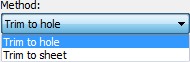
The trimming method is defined in the field “Method”. To trim by the borders of the regions being patched, use “Trim to hole”, to trim by the sheet body borders – “Trim to sheet”.
A selection of a replacement sheet body can be canceled by the option:
![]() <D> Cancel sheet body selection
<D> Cancel sheet body selection
Defining parameters when filling by any geometrical surface
You can specify a 3D object defining the geometrical surface to use for patching body regions, using the option:
![]() <U> Select surface
<U> Select surface
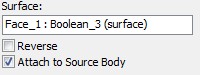
The selected 3D object is entered in the “Surface” field of the properties window.
In the complicated cases, the system may be mistaken with the direction of closing the selected contours. That means, the new faces could be applied not on the selected holes in the body, but rather around them. In such a case, use the additional flag “Reverse” that alters the direction of closing the selected regions.
Selection of a replacement sheet body can be canceled by the option:
![]() <D> Cancel sheet body selection
<D> Cancel sheet body selection
Adding the filling surface to the source body
By default, the created surfaces become part of the source body. This is indicated by the enabled flag “Attach to Source Body”.
This flag is unavailable when working with solid bodies.