External Model |
  
|
External Model |
|
This command is intended for inserting 3D models in the Parasolid, STEP, ACIS , IGES, Siemens NX (Unigraphics), Creo/ProE, SolidWorks, Catia V5, Catia V4, Autodesk Inventor, Solid Edge, Rhino, I‑Deas, JT, PRC, VDA-FS formats. The model inserted in this way becomes a normal operation of T-FLEX CAD. Remember, however, that an external model that is made of several operations becomes a single object upon inserting in T-FLEX CAD. To do further manipulations over a separate body of such model, you first need to use the operation Divide Solid.
Inserting an external model resembles creation of a 3D fragment, however, with limited capabilities. Thus, for example, you cannot set the values of external variables. Neither can you select the original attachment coordinate system (the model global coordinates are used instead).
Modes of working with external model
When inserting an external model, the current document keeps the reference to its file and its original geometry. In the future, the user can select one of the two modes of working with the external model:
● In the first mode, the system tracks all changes to the external model file. If the file modifies, the external model adjusts in the current document.
● In the second mode, the changes to the external model file are ignored. When working with the model, the geometry is used that was stored in the current document upon the last exchange with the model file. Nevertheless, the reference of the model file is saved in the current document anyway, which allows reverting to the first mode. Use of this mode provides fast handling of the current document with less memory required, however, it increases the size of the document when saved on the disk. This mode supports working with the document with an external model inserted in it, even when the external model file is absent.
The second mode is turned on automatically, if the system fails to find the external model file.
External model insertion
To insert a Parasolid-format model, use the command "3MO: Insert External Model":
Icon |
Ribbon |
|---|---|
|
3D Model → Modify → External model |
Keyboard |
Textual Menu |
<3MO> |
Operation > External Model |
To insert an external model, you need to do the following steps:
1. Select external model file. The selection of the external model file is done in the command property window or by the option:
![]() <1> Select External Model
<1> Select External Model
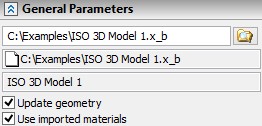
There are two additional information fields in the external model properties dialog below the file name input field. One of them displays the full path to the selected external model file, the other one - the external model source file (that is, the file based on which the Parasolid-format model was created).
The source file data is displayed on the condition that the “*.xmt” source file contains the respective information.
The “Open Source File” command will be available in the context menu of the created external model. This command opens the source file if it exists in the path specified, by using the application matching the given file type.
2. Select or create source coordinate system.
Selection or creation of source coordinate system can be done by option:
|
<S> |
Select or create source LCS |
Coordinate system of external model is used by default.
3. Select or create target coordinate system.
Selection or creation of target coordinate system can be done by option:
|
<T> |
Select or create target LCS |
This option is set automatically upon selecting the external model. Selection of the target coordinate system amounts to selecting an LCS at which the external model’s coordinate system should be placed. If no coordinate system is selected, the global coordinate system is used by default.
Selection of the target coordinate system can be undone by the option:
|
<3> |
Reset target LCS |
The process of selection/creation of source and target coordinate systems is described in the Chapter «Assigning Transformations to 3D Entities».
4. Define the external model parameters (optional).
The following parameters can be defined in the operation property window:
Update geometry. This parameter defines the mode of working with the external model. When the flag is set, the first mode is used (tracking all changes in the model file). Unsetting the flag turns on the second mode.
Use imported materials. This parameter supports use of the original materials of the external model.
The external model parameters can be defined in the common operation parameters dialog box called by the option:
![]() <P> Set entity parameters
<P> Set entity parameters
4. Complete operation creation (![]() in the property window or in the automenu).
in the property window or in the automenu).
While creating an external model, the system runs the consistency check on the imported model. If there are errors in the model, then a window is displayed with the error message and suggestions for possible actions.
An external model can also be created by executing the command "IM: Import Drawing Or Model" (see the chapter "Exporting and importing documents" in the two-dimensional design and drafting user manual).
External Model Editing
To edit an external model use command:
Keyboard |
Textual Menu |
Icon |
|---|---|---|
<3EI> |
“Edit|Operations|External Model” |
|
You can change position of chosen external model or replace it with another one, loaded from a file with the help of this command.
More information about this command can be found in the chapter "Editing".