3D Picture |
  
|
3D Picture |
|
Unlike fragments, a 3D picture is a hull of a three-dimensional object, without parametric properties and relations between the picture elements. 3D pictures are used for creating three-dimensional assembly structures.
3D pictures cannot be used as the references for creating other elements, since their faces cannot be selected. You cannot use 3D pictures in Boolean operations either. Their 2D projections cannot be created. The command "Exploded View" cannot be applied to 3D pictures.
You can insert into a T-FLEX CAD document the 3D picture files in the following graphic formats: grb (T-FLEX CAD files), wrl (VRML files), iv (Open Inventor files), x3d, 3ds, ply, obj, stl, dxf, dwg.
To save a 3D picture is part of a T-FLEX CAD document, that already contains a 3D model, set the parameter “Save 3D Picture” on the “Save” tab of the Document Parameters dialog box.
To save a 3D picture in a separate file in the iv, wrl, 3d, ply, obj, stl formats, use the command File > Export.
Remember: storing a 3D picture inside a T-FLEX CAD file noticeably increases the file size. The size of the 3D picture itself depends on the mesh density defined in the Document Parameters at the time of the picture creation.
Creating 3D pictures
To insert a 3D picture into a model, use the command "3I: Insert 3D Picture":
Icon |
Ribbon |
|---|---|
|
3D Model → Modify → 3D Picture |
Keyboard |
Textual Menu |
<3I> |
Operation > 3D Picture |
Upon calling the command, you get the access to the following actions:
|
<Q> |
Repeat existing 3D Picture |
|
<S> |
Select or create source LCS |
|
<T> |
Select or create target LCS |
|
<F> |
Select 2D Fragment |
|
<O> |
Select file |
|
<R> |
Repeat previous 3D Picture |
|
<I> |
Multiple iterated insertion of 3D picture |
To insert a 3D picture into an assembly, you need to do the following steps:
1. Select a 3D picture.
The selection can be done in two ways:
- By applying a new 3D picture (the option ![]() );
);
- By selecting an already inserted 3D picture (the option ![]() );
);
-By selecting an already inserted 2D fragment, using its 3D model (the option ![]() ).
).
2. Select or create the 3D picture's source coordinate system (the option ![]() ).
).
3. Select or create the target coordinate system (the option ![]() ). Only existing coordinate systems in the current document can be used as the target coordinate system.
). Only existing coordinate systems in the current document can be used as the target coordinate system.
4. Define the 3D picture parameters (optional).
5. Finish inputting the 3D picture (![]() in the automenu or in the property window).
in the automenu or in the property window).
Files can be selected either from the T-FLEX CAD library or from any folder on the disk.
In the drop-down list of option ![]() you can choose one of the three sources for the 3D picture.
you can choose one of the three sources for the 3D picture.
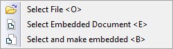
When you select option "Select and make embedded", inserted 3D picture will be stored in the current document, not in an external file. Option “Select embedded document” appears only for files with embedded documents.
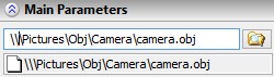
The name of the selected/internal document will be shown in the command's properties window (to the left of the button ![]() ). Grey (not accessible for editing) field, located a little below is informational and shows the absolute path to the file from which the picture is taken.
). Grey (not accessible for editing) field, located a little below is informational and shows the absolute path to the file from which the picture is taken.
If you press button ![]() after selection of the pathname, the drop-down list will appear:
after selection of the pathname, the drop-down list will appear:
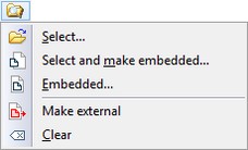
1.The first three options are the same as for option ![]() . Option "Make external" allows uploading of the embedded picture to an external file. Option "Clear" allows quick removing of the pathname.
. Option "Make external" allows uploading of the embedded picture to an external file. Option "Clear" allows quick removing of the pathname.
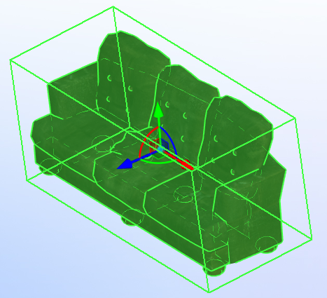
2.After adding 3D picture, you can change its position in space with special manipulator that appears in 3D window. By default, the origin of the manipulator is located in the center of the bounding box. If necessary, you can change the position of the manipulator by using option ![]() «Select or create source coordinate system». Unlike the creation of 3D fragment, the original coordinate system of the 3D picture cannot be bound to the picture, because it has no geometric data. In the rest, the process of selection/creation of source and target coordinate systems is similar to the process of inserting 3D fragments. This process is described in the Chapter «Assigning Transformations to 3D Entities».
«Select or create source coordinate system». Unlike the creation of 3D fragment, the original coordinate system of the 3D picture cannot be bound to the picture, because it has no geometric data. In the rest, the process of selection/creation of source and target coordinate systems is similar to the process of inserting 3D fragments. This process is described in the Chapter «Assigning Transformations to 3D Entities».
3D Picture Properties
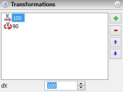
Transformations of 3D picture (translations and rotations) are displayed in the "Transformations". Optionally section of the properties window. Optionaly, you can specify exact values for any transformation in the list.
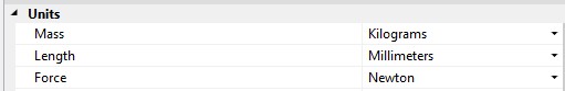
For the inserted 3D picture can be specified the units of measurement. After that, its size will be automatically recalculated. This function is useful for formats, which do not contain data about source measurement units of the picture. In this case, system will use measurement units specified in section “3D” of “Document Parameters ” command.
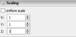
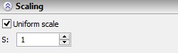
In the properties window, you can specify the scale of 3D picture. The scale may be uniform along all axes or can be set separately for each axis. To specify a non-uniform scale it is necessary to remove the flag "Uniform scale".
|
|
In section “Options” you can set flag “Create internal document”. If the flag is active, the picture file is saved in the current document. This allows you to increase the speed of data loading. Otherwise, when you open a document, the system loads an external picture file.
Option ![]() allows to reinsert previously created picture.
allows to reinsert previously created picture.
Option ![]() starts multiple insertion of previously created picture. The insertion is repeated until it is interrupted.
starts multiple insertion of previously created picture. The insertion is repeated until it is interrupted.
Use of 3D Pictures for Creating Layouts
When creating layouts based on objects with fixed dimensions, we recommend using 3D pictures. When rebuilding such 3D assembly models, 3D picture regeneration is much faster than assemblies consisting of 3D fragments.
The layouts using 3D pictures are created in the same way as those based on 3D fragments, with the only difference that the 3D picture is not created automatically when inserting a 2D fragment. The 3D picture is inserted manually by selecting the 2D fragment.
When inserting a 2D fragment for creating a layout using 3D pictures, make sure that the flag is turned off, “Create 3D Fragments automatically”, on the "Fragments" tab of the command "SO: Set System Options").
You can get the detailed description of this system capability in the chapter “3D Assemblies Creation” (the section “Assembly creation from 3D fragments. ‘Bottom-up’ design technique”) with the corrections for 3D pictures.
Only 2D fragments that were saved with enabled option “Save 3D Picture data in model file”, can be used for layouts. Note also that only rendered views may be created as 2D projections of assemblies built from 3D pictures.
Usage of Coating Materials
You can apply coating material for 3D pictures. There are two ways to do it.
The first way is to apply the coating material to the 3D picture using “drag'n'drop” function. For this purpose, you need to open window "Materials" and to use the coating material from the list of model materials or from the "Coatings" library.
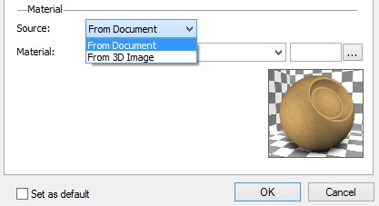
The second method is to choose the coating material in the properties window of 3D picture. To do this, press option ![]() in automenu and choose the tab “General”. Then, in the drop-down list of field “Source” select option “From document”. After that, the field “Material” becomes available. In this field, you can select the coating material for 3D picture.
in automenu and choose the tab “General”. Then, in the drop-down list of field “Source” select option “From document”. After that, the field “Material” becomes available. In this field, you can select the coating material for 3D picture.
It is important that the coating material can be applied only for the entire 3D picture, because it represents a single object.
3D Pictures Editing
To edit a 3D picture use command:
Keyboard |
Textual Menu |
Icon |
|---|---|---|
<3EI> |
“Edit|Operations|3D Picture” |
|
More information about this command can be found in the chapter "Editing".
When editing a 3D picture it is possible to replace it with another one. This new picture can be either loaded from a file or can be defined by selecting other existing picture from the scene. For the last case, you need first to use option:
|
<F4> |
Execute edit command |
Next you need to select option ![]() in automenu and click on any existing 3D picture in the scene. Current 3D picture will be replaced with it.
in automenu and click on any existing 3D picture in the scene. Current 3D picture will be replaced with it.