Fixing Vectors. Connectors |
  
|
Fixing Vectors. Connectors |
|
A fixing vector and a connector auxiliary elements of the model which are used when attaching the fragments. These construction elements are constantly displayed on the screen and can be hidden together with other construction elements by the command "Hide Construction". Context menu is available for those elements, providing the deletion, editing and property modification commands.
To use a fully furnished drawing as a fragment, one needs to create a fixing vector. To prepare the environment for fast "snapping" of other fragments, one needs to create a connector. The connector does not have to be created in the fragment drawing. It can be created in an assembly drawing.
Fixing vectors and connectors have different purpose, however, are created in the same command "FV: Construct Fixing Vector":
Icon |
Ribbon |
|---|---|
|
Draw → Insert → Fixing Vector |
Keyboard |
Textual Menu |
<FV> |
Construct > Fixing Vector |
Upon calling the command, the following options appear in the automenu:
![]() <F> Create Fixing Vector
<F> Create Fixing Vector
![]() <C> Create Connector
<C> Create Connector
![]() <A> Set Snap Elements
<A> Set Snap Elements
![]() <N> Select Node
<N> Select Node
![]() <F4> Execute Edit Fixing Vector Command
<F4> Execute Edit Fixing Vector Command
![]() <Esc> Exit command
<Esc> Exit command
Fixing vector properties
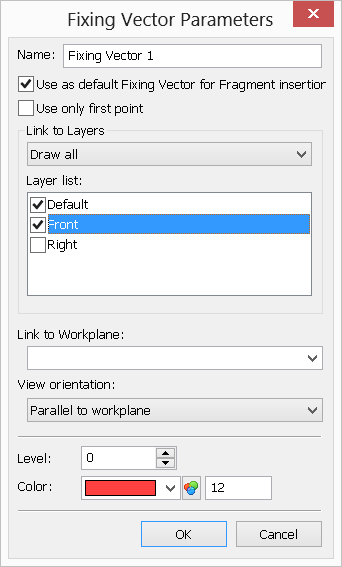
There are two types of fixing vectors: a fixing vector defined by two points, and a fixing vector defined by one point. Fixing by one point is used for fast attachment of parts, whose image does not change under rotations, or parts not requiring rotation.
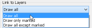
When creating a fixing vector, in its parameters specify the layers of the drawing to be displayed in the assembly. This allows, for example, inserting different views of the same part in an assembly.
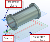
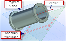
If the 3D model exists in the document, then the fixing vector can be bound to a specific workplane. This allows using 2D fragments in three-dimensional assemblies for defining the position of a three-dimensional fragment in the space with respect to the final position of the fixing vector and the selected workplane. This assembly creation technique is called "Layout". Detailed information on this technique can be found in the three-dimensional modeling manual, the chapter "3D Assemblies". This kind of relation allows inserting a 3D fragment automatically when the respective 2D fragment is assembled. To enable this feature, set the flag "Create 3D Fragments Automatically" in the command "SO: Set System Options", the tab "Fragments".
Fixing Vector defined by two points
When inserting a fragment with such fixing vector, the position of the first point (the vector start) will be defining the fragment placement position within the assembly drawing, while the second point position (the vector end) - rotation of the fragment in the assembly. To create such vector, subsequently select two nodes by clicking Layer list. This pane contains the list of all layers existing in the drawing. Here you can mark those that will be displayed when assembling the document as a fragment using this particular fixing vector. |
|
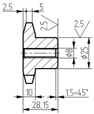
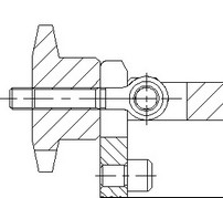
On the diagram below, highligted are the fixing vector and the drawing elements to be carried over to the assembly drawing. Those elements are assigned a new layer. Exactly this layer must be check marked in the fixing vector parameters.
After that, when assembling these drawing as a fragment, only the check marked layer will be displayed in the assembly drawing, and, therefore, only the elements that lie in this layer will be displayed.
If a fixing vector has linked layers, its context menu will provide the command "Apply Layer visibility". Calling this command shows or hides the layers in the way in which they will be displayed when assembling the document as a fragment, using this fixing vector.
Link to Workplane. This parameter has a meaning only in the 3D version of the system. It servers for defining the workplane to which the given fixing vector will be bound. This functionality is used when creating layouts (see the chapter "3D Assemblies").
View orientation. View orientation is used when creating layouts (2D fragment on a workplane by 3D fragment). It allows us to select condition for which the schematic view will be added to the assembly’s plane. Only three options are possible:
●«Parallel to workplane» − after addition of the model to the assembly, the model’s schematic image will be created only under condition that the workplane of the assembly is parallel to the workplane in the file of the fragment with which the vector is linked.
●«Axial symmetry» − it is used for models of body of revolution type. After addition of the model to the assembly, the model’s schematic image can be created on any plane of the assembly which is parallel to a line on which the fixing vector is lying.
●«Arbitrary orientation» − it is used for bodies with central symmetry or having identical pseudo-graphical display of several views. After addition of the model to the assembly, the model’s schematic image can be created on any plane.
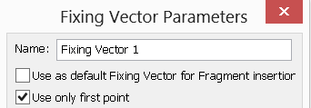
Fixing Vector defined by one point
To create such fixing vector, select a node in the drawing by clicking |
|
When inserting a fragment, only one point will be asked. It won't be possible to define rotation for such fragment. If the flag "Use only first point" is not set, then a two-point fixing vector will be created. The direction of such fixing point will coincide with the X-axis of the fragment drawing.