Intersection Check |
  
|
Intersection Check |
|
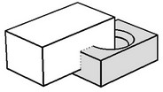
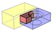
This command allows checking the model for intersections and contacts of the selected bodies. The command is particularly helpful when working with assemblies.
To call the command "QI: Check Model Intersections", use the textual menu:
Icon |
Ribbon |
|---|---|
|
Measure→ Geometry analysis → Intersection Check |
Keyboard |
Textual Menu |
<QI> |
Tools > Geometry Analysis > Intersection Check |
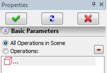
The command offers two checking modes: checking intersections of all bodies in the scene, and checking intersection of the selected operations. The desired mode is selected in the property window.
Upon entering the command, the "All Operations in Scene" button is pushed in the property window. Therefore, you can finish input immediately and run the check for intersection of all operations in the scene.
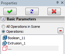
If the scene is rather complex, contains numerous bodies, and the bodies have complicated geometry, then checking intersection of all bodies in the scene can take long time. In such cases, you are advised to directly specify the bodies whose intersection needs to be checked. To do this, use the option
![]() <F> Select source 3D operation
<F> Select source 3D operation
Once an operation is selected, it will be added to the checklist, and the "Operations" button will be pushed automatically in the properties window. Upon finishing the input, the check for intersections will be run on the listed operations only.
To delete a specific operation from the checklist, use the button ![]() . To cancel selection of all bodies, you can simply switch to the "All Operations in Scene" mode, and the list of the operations to check will be cleared.
. To cancel selection of all bodies, you can simply switch to the "All Operations in Scene" mode, and the list of the operations to check will be cleared.
To run the intersection check, use the option:
![]() <Enter> Finish input
<Enter> Finish input
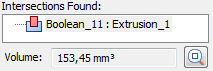
Upon finishing the check, the results will be displayed in the "Intersections Found" pane. If you click an intersection report, the intersecting bodies will become semitransparent in the 3D window and change the color, while the intersection region will be brightly highlighted. The volume of the bodies' intersecting region will be displayed in the "Volume" pane. If the intersecting region is too small, you can use the button "Zoom in", and the image of the intersection region will be magnified. |
|
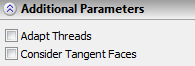
Depending on the specified additional parameters, the analysis results will be displayed differently in the "Intersections Found" pane. The command provides two additional parameters, "Adapt Threads" and "Consider Tangent Faces". |
|
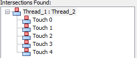
Often, one part is connected with another one by a thread. In this case, with the "Adapt Threads" parameter set, the system will be taking into the account thread parameters of the intersecting operations and, in the case of finding a mismatch in some thread parameters (for example, the pitch), the message "Face geometry doesn't match thread standard" will be displayed in the "Intersections Found" pane. If you click this message, the respective faces with the thread will be marked in the 3D window by dashed lines. By default, the system accounts only for intersections of the bodies penetrating each other. If the "Consider Tangent Faces" option is set, the system will be also accounting for touching contacts, besides intersections of operations. Therefore, the touching faces of the operations will be mentioned in the "Intersections Found" pane, besides intersections and mismatching thread parameters. |
|
If you click a report about a touch, the respective faces will be marked by dotted lines in the 3D window.