Features and Area of Application
T-FLEX CAD is a parametric design and drawing system. T-FLEX provides high levels of drawing flexibility and supports modifications of the drawings while maintaining constraints imposed by the designer on the drawing elements. The unique parametric engine and a complete set of professional tools for computer-aided design simplify the design workflow and speed up preparation of drawing materials. T-FLEX CAD gives a designer a familiar feel of working with traditional paper and ruler equipment.
Associative design driven by assigning and modifying variable parameters is the way to follow by all design and drawing automation systems. The particular success of T-FLEX CAD is based, in the first place, on the new paradigm of geometric modeling. This paradigm is about a new, deeper, level of parameterization, compared to other systems. The idea of parameterization itself has nowadays become a standard in CAD. By "parameterization" we usually mean a provision for a drawing extensive reuse by means of modifying its parameters. Virtually all CAD vendors claim parametric capabilities of their systems. However, these systems, originally introduced long before parameterization was adopted, often use their legacy data structures that are inherently non-parametric. This causes their solutions to suffer from ineffectiveness or limited range of applicability. The T-FLEX CAD's revolutionary approach to the idea of parameterization and the fact that the drawings are based on inherently parametric models provide a new dimension for parametric design.
T-FLEX CAD uses concepts and practices that are familiar to designers. At the same time, the user does not need to care about making a precise drawing at once. The modification capabilities via both dimensioning and free dragging are unmatched across other CAD systems.
The assembly drawing environment is unique in its wide range of capabilities. T-FLEX CAD permits creating complex drawings where certain fragments can be bound by relations. A relation can be established either via geometrical properties or by parameters. The system correctly handles lines visibility throughout modifications, if some portions of the drawing overlap the others, with no limitation on the number of overlaps. It takes seconds to create drawings of a new product in a family by varying assembly drawing parameters. The modifications instantly reflect not only on the assembly but also on the member fragments (parts) and all the rest of the related documentation.
One typical attribute of the parametric CAD systems is a language for programming parametrical relations. T-FLEX CAD has another advantage in this area. The engineer is not required to have any training in programming. The drawing parameters can be represented by variables. These variables can be related in simple mathematical expressions. This is done without using any programming language. The variables can be assigned either at creation of an element or while editing an existing one. The values of the variables can be obtained from other drawings or automatically input from a database. This provides for unlimited modification capabilities in drawing.
Along with parametric design, T-FLEX CAD supports wide usage of quick drawing producing non-parametric sketches. This approach allows creating drawings in a way similar to major CAD systems by using a standard set of tools for drawing, i.e. various primitives, as arcs, circles, line segments, etc. The snapping mechanism is provided for easy sketching of new entities, such as horizontal and vertical alignment of the cursor with the existing entities or their ends, center-of-arc and center-of-circle snapping, etc. When creating arcs, snapping occurs around the 90, 180 and 270 degrees. The cursor also snaps to horizontal and vertical alignments with the arc center. The system automatically identifies multiple pairs of same-object snappings. Snapping to any object can be locked with the Function key, and the cursor will follow to the locked snapping condition. Thus, the sketcher provides a way of quick drawing, however, such drawings do not take full advantage of parametric dimension modifications. Therefore, this method is only recommended when no substantial modifications are expected on the drawing.
Creation of parametric construction-based drawings can be accelerated with the special parametric sketch mode. This mode combines efficiency of non-parametric drafting with flexibility of parametric construction. This goal is achieved by simultaneous actions of a user and the application: user creates his drawings using ordinary sketch features, and application “puts” geometrically related construction elements under the sketch lines thus producing a parametric drawing.
The highly effective functionalities of T-FLEX CAD make the system usable in a wide range of situations. The system can well be used in mechanical design, such as design of industrial equipment and tooling, development of molds and stamps, design of consumer goods, etc. It also supports development of manufacturing process flow charts and BOM, numerically controlled machining and other technological procedures. Other possible application fields include construction and architectural design, charting various types of graphs, dynamical visualization of processes and mechanisms, industrial and graphic design. The most effective uses of T-FLEX CAD occur when the parametric design paradigm dominates the design process, and when all stages of design are involved, from sketch to scratch drawing to production drawing. T-FLEX CAD facilitates considerable speed-up of graphic design and documentation cycle.
T-FLEX CAD offers a complete range of drawing tools, such as creating various-type line drawings, hatches, dimensions, text, roughnesses, special symbols, etc. Important that all these design attributes can be associated with the parameters of the drawing. This means, modifying a drawing parameter would cause adjustment of the design attributes. The drawings follow the user-specified international standard. T-FLEX CAD also supports instant switching from one drawing standard to another.
The three-dimensional version CAD 3D is intended for making parametric 3D models. The 3D solid bodies authored by the system can easily be modified. Parametric modifications of the 2D drawings propagate on the model's 3D representation, and vise versa.
T-FLEX CAD can be used as a base for developing specialized CAD systems. The system supports exporting parametric drawing data to custom processing modules. Vise versa, externally generated parameter values can be imported into the system and assigned to the drawing parameter variables. The model is then automatically regenerated, and the new design drawing is ready.
The system software utilizes the latest GUI standards. Even a novice user can easily start working with the system. The menu and icon layout is easy to use. The command dialog boxes are intuitive. The various drawing elements and the libraries of drawings allow effortless manipulation. The built-in context-dependent Help facilitates quick learning. Every command is realized in a way that provides users – engineers and designers - with confidence in operating the system.
The theory and algorithms used in the system are unique yet unambiguous to end-users.
Conventions adopted in the T-FLEX CAD guidelines
The following standard conventions are adopted in this document:
<Enter>, <L>, <Esc>, etc. – notations for the keys on the computer keyboard.
[OK], [View], etc. – notations for graphic buttons in the dialog boxes.
![]() - Left mouse button click.
- Left mouse button click.
![]() - Right mouse button click.
- Right mouse button click.
![]()
![]() - Left mouse button double-click.
- Left mouse button double-click.
![]() ,
, ![]() , etc. – icons on a toolbar, ribbon or automenu.
, etc. – icons on a toolbar, ribbon or automenu.
File > Open… etc. – selection of a textual menu bar item File, followed by a pull-down menu item Open….
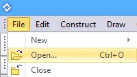
Properties > Product structure properties > Don’t include invisible objects, etc means that you select Don’t include invisible objects item in the Product structure properties group of the Properties tab in the dialogue window.

O: Open Model, EL: Construct Ellipse, etc. – selection of a textual menu bar item "File", followed by a pull-down menu item "Open…". "Font|Name" etc. – selection of a tab "Font" in a dialog box followed by an item "Name", or selection of a group of parameters in a dialog box followed by a particular parameter.
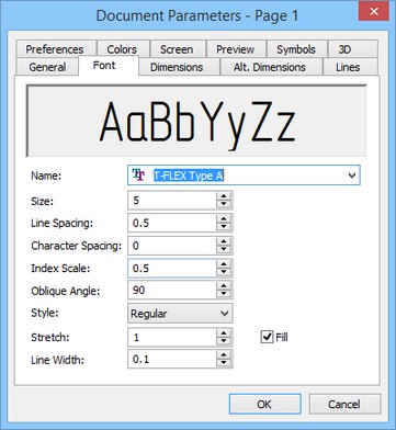
"O: Open Model", "EL: Construct Ellipse", etc. – names of T-FLEX CAD commands. Note that the character combinations before the colon define the keystroke accelerator sequences for invoking commands by typing in the status bar.
A command can be invoked in T-FLEX CAD by the following three ways:
By typing,
By selecting the toolbar item, and
By selecting the textual menu/ribbon item.
The system manuals describe the commands in a table. For instance, the command "QL: Layers" would appear in a table as follows,
Icon |
Ribbon |
|---|---|
|
Edit → Document → Layers… |
Keyboard |
Textual Menu |
<QL> |
Customize > Layers |
This means, the command can be invoked in the following ways:
1.Press the key <Q> then <L> on the keyboard,
2.Select Customize item in the text menu and activate Layers… command from the drop-down list.
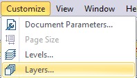
3.Select the icon ![]() in the appropriate toolbar.
in the appropriate toolbar.

4.Select Layers command in the Document group of the Edit tab.

Certain most common commands can also be invoked with the function keys. For instance, pressing <F7> causes Redraw operation.
Select an element instruction in the manuals means placing the cursor over the element and pressing left mouse button ![]() or <Enter>.
or <Enter>.
Select an icon, press an icon, select an input box, press a button instruction means placing the cursor over the item (icon, input box, dialog box button) and pressing left mouse button ![]() .
.
Point at an element, point at an icon, point at a button means just placing the cursor over the item.
Each command usually brings a list of options available under this command. An option is one specific action performed within the command, as delete an element, select an element of a particular type, switch to another mode, etc.
Each option is represented by a button and an icon in the automenu.
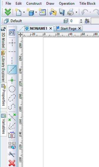
Invoking an option via the keystroke mechanism might be different than by selecting the icon. Typing the keystroke sequence instantly invokes the action, while selecting an icon may work in two ways. First possibility is – an instant action occurs, as, for instance, when specifying parameters of an element via ![]() .
.
Second – after selecting the icon, the system waits for a specific user action, with the cursor being modified with a glyph corresponding to the action. The action completes when the cursor is pointed at an appropriate element and left mouse button ![]() pressed. For instance, this can be a selection of a construction line –
pressed. For instance, this can be a selection of a construction line – ![]() .
.

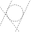
The command description contains various ways of creating elements. For instance, the following sequence describes creation of a construction circle:
<L>, <L>, <L> - a circle tangent to three lines. The above sequence uses a typical notation which implies that the respective automenu icon picks can be used instead of the keystrokes, for instance,
<L>, ![]() , <L> is a way of creating a three-line-tangent circle using both the keystrokes and the icon.
, <L> is a way of creating a three-line-tangent circle using both the keystrokes and the icon.
![]() ,
, ![]() ,
, ![]() is a way of creating a three-line-tangent circle via the automenu icon picks.
is a way of creating a three-line-tangent circle via the automenu icon picks.
![]() , <L>, <L>, etc. – other possible combinations.
, <L>, <L>, etc. – other possible combinations.
In the system description, "Press ![]() " usually means that either left mouse button
" usually means that either left mouse button ![]() or <Enter> key can be pressed. The <Enter> key works as
or <Enter> key can be pressed. The <Enter> key works as ![]() while working within the command dialog box.
while working within the command dialog box.
In the system description, "Press ![]() " means that either right mouse button
" means that either right mouse button ![]() or <Esc> key can be pressed. This convention about
or <Esc> key can be pressed. This convention about ![]() also holds when working in the drawing area of the application. Use of
also holds when working in the drawing area of the application. Use of ![]() in other areas of the screen follows the standard conventions of Windows (usually, this invokes the context-sensitive menu).
in other areas of the screen follows the standard conventions of Windows (usually, this invokes the context-sensitive menu).