This document presents a review of new functionalities, capabilities and enhancements of T-FLEX CAD version 9. This information is mainly intended for advanced users possessing good working experience with main system instruments. For in-depth acquaintance with the system functionalities, refer to the respective sections of Help or User Manual.
"Express Analysis"
The new T-FLEX CAD version includes free "Express Analysis" module. This module is the lightweight version of "T-FLEX Analysis" package, specifically tuned for conducting simplified yet representative strength analysis.
At user's disposition there is the necessary set of load and fixture types. Starting off with T-FLEX CAD model geometry, the automatic express analysis simulator creates a high-quality finite element mesh. Upon completing the calculations, the strain, stress, displacement and strength capacity results are graphically presented.
In this way, the express analysis module lets the engineer quickly determine peak stress locations and extent of deformations, identify structural elements that carry excessive material. This helps significantly increase effectiveness and quality of design.
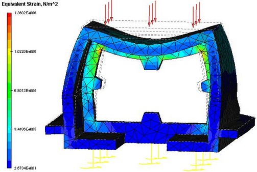
Since the analysis is conducted in a parametric system, the user will not be required of additional actions in the case of a repeated analysis upon introducing parametric changes in the model.
Mates
In the process of designing solid assembly models in T-FLEX CAD, it is often necessary to specify mutual position of parts, which may not always be accomplished by the conventional technique of fixing by LCS adopted at T-FLEX CAD. Such tasks may occur, for example, when building models of mechanical systems (mechanisms).
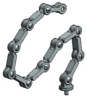
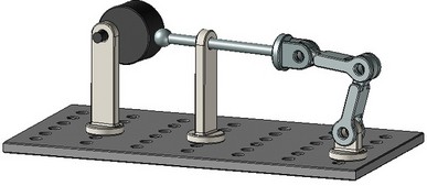
The system gained a totally new tool of "Mates". It serves for mutual attachment of assembly model elements and allows positioning those according to the specified geometrical conditions. These conditions define the mutual situation of the three-dimensional model objects (such as faces, edges, vertices, characteristic points, axes of surfaces of revolution, etc.) with respect to each other. The system automatically resolves the specified set of mates and positions the objects in the way satisfying the specified conditions. The method of positioning the selected parts by using mates is to be used as an auxiliary way of fixing together with the use of fixing by LCS.
Two new commands are introduced for handling mates: "Create mate" and "Move mated elements".
The following mate types can be created in the system:
· Coincidence
· Parallelism
· Perpendicularity
· Tangency
· Concentricity
· Distance. The "distance" constraint defines a relation between two objects by fulfilling the condition of maintaining a specified distance between two geometrical objects. One can specify the conditions of types "no greater than", "no less than" or "equal" to the specified value.
· Angle. The "angle" constraint defines a relation between two objects by fulfilling the condition of maintaining a specified distance between two geometrical objects. One can specify the conditions of types "no greater than", "no less than" or "equal" to the specified value.
Mates are displayed in the model structure in a separate folder. The user can manually sort them into groups.
When fixing 3D fragments to local coordinate systems, one can specify mating conditions in the way of permitted degrees of freedom. If such a 3D fragment is mated in the future to another constrained element in an assembly, it will be included into the combined constrained mechanism.
The so-called "Aggregate" tool is introduced in the system for creating complex assemblies. This tool allows creating mates in the model of the 3D fragment first, so that those are automatically accounted for when such a 3D fragment acts in an assembly.
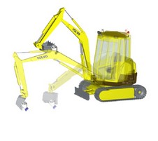
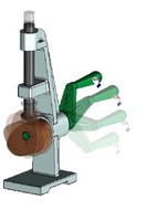
The command "Move mated elements" provides dynamic control over positions of the elements mated with each other. It allows interactivity moving model elements in the 3D window according to the existing degrees of freedom. There is a choice of various moving options that account for properties of bodies in different ways.
The T-FLEX CAD mating mechanism possesses several significant advantages over analogous mechanisms in other 3D modeling systems:
· "Mates" appear as a natural extension to the traditional way of fixing by coordinate systems and via transformations. Those provide the slick way of defining element position inherent to LCS while accounting for the situating methods beyond LCS capabilities.
· The tools can be successfully used for both the mates within assembly models and for positioning operand bodies for oncoming modeling operations.
· The cutting edge technology of solving mates allows handling traditionally complicated tasks – for example, mating a cam of an arbitrary shape with a spherical pushrod. Note that no special conditions are imposed on the cam in this way – it is even permitted to have sharp corners on its surface. Another interesting example is the so-called "maltese cross drive" mechanism that can also be described by the introduced tools.
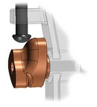
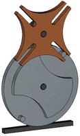
· Modeling of a mechanism's motions is much more realistic than in the case of many other systems, thereby enabling a designer to examine a mechanism's behavior as early as at the model building stage.
New Commands for 3D Modeling
Face Processing Operations
A number of new commands are introduced for handling body faces. All face-manipulating operations are united in one common group. The previously existing "Sew" operation is also included in the group.
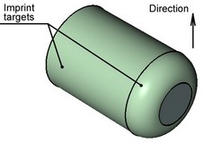
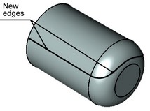
This command is used for defining areas of specified shape on already existing faces. This might be necessary, in particular, for imprinting separator lines and surfaces into a 3D model as part of preparation for FEM analysis. Those elements could be used, for example, for defining forces applied to the model. An element being split (the imprint target) can be one or several faces, or a whole operation. Those elements will serve as a basis for creating the new faces. Depending on the splitting method, the shape of the new area is defined based on either the shape of the dividing element (the imprint tool), as Face, Edge, 3D Profile, Operation, or based on the geometry of the imprint target elements. The illustrated techniques are shown below:
Specify mapping direction:
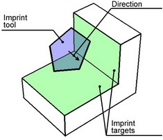
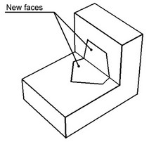
Normal mapping:
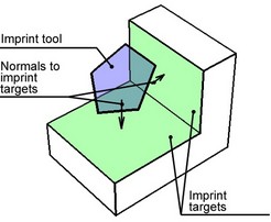
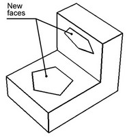
Intersection:
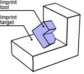
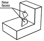
Map outline:
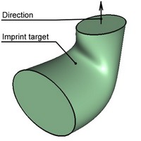
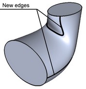
By isocline:
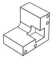
This command allows deleting one or several selected faces. Face deletion breaks solid body topology. The introduced voids invalidate the closed volume. If required, the system can attempt healing those by various means. Otherwise, the result will be a sheet body.
The operation is used in surface and solid modeling, when local changes to the model topology are desired, without affecting the original relations. It can also be helpful when preparing a model to finite element analysis, for such tasks as removal of small model features that are insignificant to the calculations.
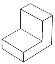
This command allows excluding selected faces from an already existing body, and creating a new body based on them. The resulting voids in the bodies can be closed by one of several methods.
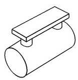
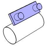
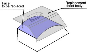
This command allows replacing a geometrical surface underlying the selected face, by another geometrical surface.
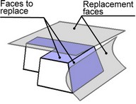
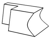
As a result, the face being replaced changes its shape according to the shape of the replacement surface. The side faces that bound the face being replaced are extended or trimmed to the intersection with the replacement surface. This command allows simultaneously processing multiple faces. A sheet body can be used as the replacement surface.
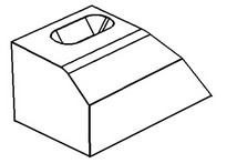
This command allows modifying parameters of the faces whose underlying surfaces are analytical (cylinder, cone, sphere and torus), as well as the parameters of faces created by a blend operation.
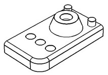
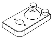
Parameters vary depending on the face type, and can be shared across all faces or be specific to a face. The required condition for executing the command is, the face being modified must be "surrounded" by the adjacent faces.
This new command allows applying a translation/rotation transformation to one or multiple selected faces. By executing the command, the selected faces are moved to a new position and, if requested, extended (or trimmed) to achieve an intersection with the surfaces of the adjoining faces. The adjoining faces, in turn, are extended (or trimmed) to the intersection with the faces being transformed.
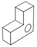
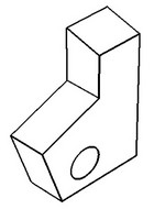
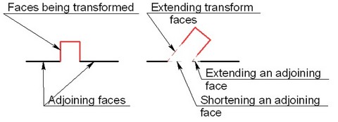
This command allows extending a selected face (or several faces belonging to a sheet body) in the specified direction, for the specified length amount. The direction of extending the face is defined by selecting the side edges of the faces being extended. 3D profiles can be extended as well. In this way, an enlarged face will be created as a result of executing the command, identical in shape with the underlying surface of the 3D profile.
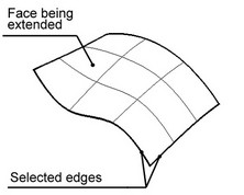
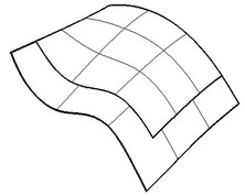
This command creates one or several faces spanning an area bounded by a closed loop of edges. When executing the command, the system tries to fill the gap using an analytical or ruled surface or next to the specified sheet body, depending on the original geometry.
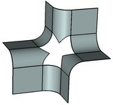
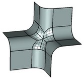
This command allows separating the original body into pieces and tapering side faces of the resulting portions by the specified angles, all in one operation. The operation could be useful for creating models of die-cast and injection molds. Unlike "Face Taper" command, this operation allows creating two-sided tapers and tapered body faces without having a clearly defined "fixed" edge.

The source body itself can be used as the parting object. As shown on the diagram below, an isocline of source body faces is selected as the set of base edges for taper creation.
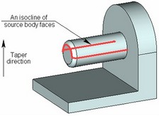
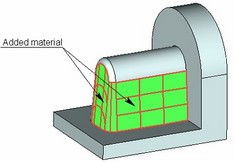
The command also provides a number of additional settings for enhancing and tuning up the result. Those include control of angular adjacencies, concave edge correction, processing of tapered faces connections, mitered taper, edge replacement.
Geometry Analysis
A new group of commands is introduced for advanced analysis of a model's geometrical data. The group has united already existing geometry analysis commands (Mass-Inertia Properties, Intersection check, Measuring curvature of surfaces) and gained new ones.
This command serves for analyzing the selected body in order to expose errors in its geometry. Errors may become an obstacle on the way of future manipulations with the model. Errors in geometry may occur, for example, due to deficiencies of importing 3D models from other systems. Sometimes, however, errors may be introduced at the time of creating a 3D model in T-FLEX. Examples of some typical errors are shown below.
|
|
|
Mismatching loops |
Self-intersection |
Mismatching faces |
The command has been improved: the user interface became friendlier due to integration with properties window; it is now possible to display intersection areas and calculate intersection volume. A capability is also added of accounting in a special way for threaded connections of parts and cases of contact between surfaces, when running body intersection check.
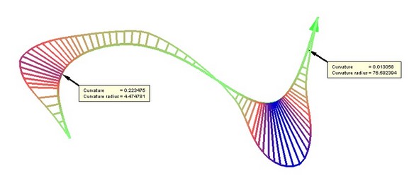
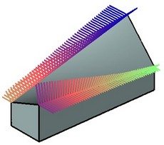
This command allows measuring curvature and the curvature radius of the selected curves. You can select edges and 3D Paths to measure curvature. Right after selecting an element, its curvature will be measured and displayed in the 3D window as a multiplicity of colored lines stemming from the curve, called curvature porcupine quill. Besides the color-coded curvature display, a provision is made for reading the curvature at a specific point. The command also allows automatically finding the maximum curvature point.
Measuring Curvature of Surfaces
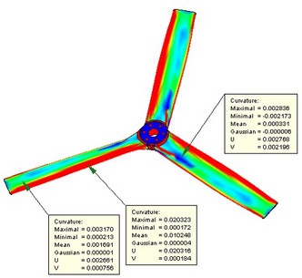
The command has been improved. Curvature measurement methods in U and V directions are added. Also added is a capability of measuring the radius of curvature in all directions.
The capability of measuring curvature at a point is improved. Now, one can set an unlimited number of measurement marks and automatically generate reports on measurement results. Automatic scanning is added for the points of maximum and minimum curvature of the given type.
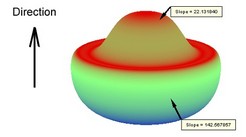
This command finds deviation of the normal from the specified direction for the selected face.
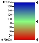 Color scale
The colored image of the face allows viewing the deviation over all face area. It is also possible to measure deviation at a specific point.
This command evaluates the gap between two or several selected faces. The system calculates the distance between edges of the selected faces. Note that the command is intended for approximate evaluation (by the quill color and length) of the distance between edges across their extent, rather than for exact measurement of distances between points on the edges.
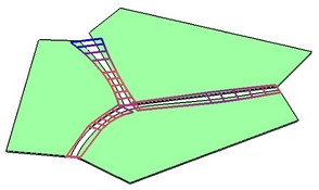
This command measures deviation of the normals on the adjacent faces at the selected edges. The quills displayed in the 3D window allow viewing deviation of normals across the extent of an edge. You can also measure the angle of normals deviation at a specific point.
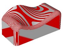
The command provides for qualitative evaluation of regularity in a model's geometrical surfaces by applying a special pattern to faces or bodies (usually consisting of bright and dark stripes). The pattern is applied in a way simulating reflection from selected surfaces. In this case, one can evaluate regularity of an individual surface (for example, by apparent "waves", folds, etc.), as well as types of transition between two surfaces (continuous tangency or continuous curvature).
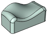
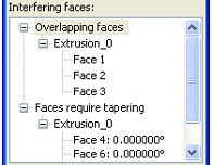
This command performs separation checks on parts of injection or die-cast molds, designed for producing three-dimensional models. The command allows finding the faces of the regions preventing the mold from parting. Additionally, the faces are highlighted, whose taper angle with respect to the selected direction is less than specified.
The new tool of "Adaptive 3D Fragments" considerably increases parametric capabilities of the 3D modeling system. This mechanism allows using not only variables, but also geometrical elements as external parameters. The instantiating value of an external geometrical parameter can take on the geometry of arbitrary assembly elements of the respective type (a solid, 3D node, 3D path, 3D profile, workplane, LCS, vertex, edge, face, loop). The idea of the approach is using the substitution geometry of an assembly element instead of the original geometry of the external parameter in the structure of an adaptive 3D fragment when regenerating a particular instance of its model. In this way, the 3D fragment acts as if "adapting" to the objects of the assembly model. For example, adaptive 3D fragments are used in special operations of inserting holes and creating stamped features in the appropriate system commands.
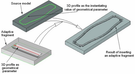
To prepare a model for use as an adaptive 3D fragment, the new command Tools|Adaptive Fragment is provided. It allows the user to prepare a set of model elements that will be later offered for substitution when inserting such a 3D fragment in an assembly. The 3D fragment insertion command has also been reworked to support adaptive fragments. When inserting an adaptive 3D fragment, the user can select elements that will be used for instantiating geometry of geometrical parameters. By default, the list will be matching the one composed in the command "Adaptive fragment". If necessary, the user can add more elements to this list. In this way, any assembly model fragment can be converted to an adaptive fragment.
Command for Projecting 3D Nodes and Vertices
Now, a new command became available while drawing on an active workplane, that creates projections of 3D nodes and vertices. The command creates a 2D node, which is the projection of the selected 3D node or vertex on the active workplane.
Changes in the 3D Modeling and Drawing Commands
The commands of creating arrays in the system have been largely reworked. The new version of T-FLEX CAD supports creation of the following types of arrays (by the type of copied elements):
· Arrays of operations. This type represents the conventional arrays supported in earlier system versions.
· Arrays of Bodies. This array type supports propagation of modifications from the array's source elements, such as creation of new operations within the source Bodies. Changes automatically propagate onto new Bodies created by copying.
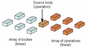
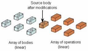
· Array of faces. This array type supports multiplication of a set of faces belonging to one solid or sheet body. Examples of such sets of faces are a hole, a protrusion, a groove, etc. The faces for copying can be selected directly or via the elements (edges, loops) confining the given set. In the latter case, the system automatically determines the set of faces. For example, to copy a blind hole of any complexity, one needs to select just the round edge of its boundary.
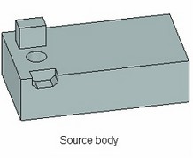
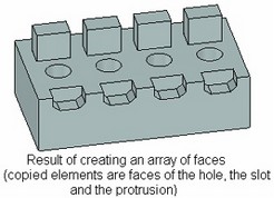
· Array of construction elements. This array type can be used for multiplicating any construction elements (workplanes, 3D nodes, 3D profiles, 3D paths, LCS).
Arrays of all above-listed types can be created into any shape of a 3D array ("Linear array", "Circular array", "Array by points", "Array by path", "Parametric array"). All array creation commands gained numerous additional capabilities. Those include:
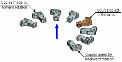
· Setting reverse direction of copies placement.
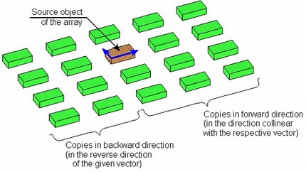
· Specifying the number of copies in the forward and reverse directions, symmetrical copying in the reverse direction.
· Defining a limitation face or set of faces for the array. When setting such faces, the elements are excluded from the array whose projections do not fall within any of the selected faces.
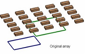
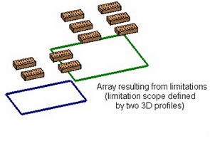
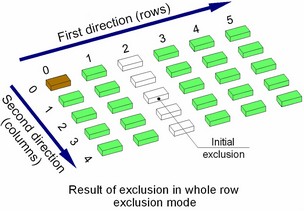
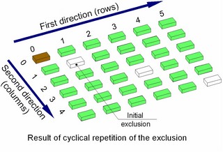
· Specifying elements to be excluded from the array. An element to be excluded can be selected directly on the screen or specified by the numbers of a row and a column. In addition, a whole row or a whole column can be excluded altogether. Besides that, exclusion can be cyclical, as, for example, "Excluding each fifth array element".
· Merging the operation results together. With the respective option active, the resulting bodies of the array are automatically subjected to the Boolean. This results in a single body.

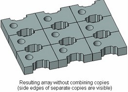
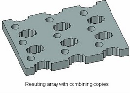
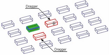
Significant enhancements are made to user interface of the array creation command. All commands use the properties window for defining parameters. To define the step and the number of copies, one can use draggers, which provide mouse control over those parameters. The operation preview instantly updates on the screen.
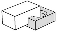
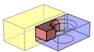
The Boolean functionality has been significantly improved. Boolean operations can now be successfully used in hybrid modeling involving both solid and sheet bodies. A capability is introduced for explicitly specifying the type of the body (solid or sheet) resulting from the operation.
When Booleans are applied to sheet bodies or to solid and sheet bodies, the sheet bodies can be interpreted as "semi spaces". Therefore, Boolean subtractions and intersections can be applied to those bodies, resulting in new solids.
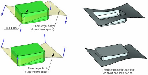
Example of addition of a sheet and a solid.
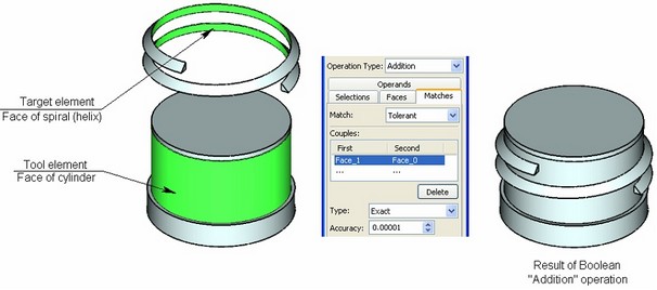
When creating a Boolean, it is possible to explicitly specify element correspondence in the cases of contact. This enables the system to perform previously unattainable tasks and significantly improve accuracy and performance of the operation execution in some cases. As an example, consider the operation of placing a helical thread on a cylindrical surface (the case dealing with a contact between a spline surface and an exact analytical one). If the user selects the cylinder and the base of the thread as the surfaces in contact, the union operation works faster by an order of magnitude and more robustly than in previous system versions.
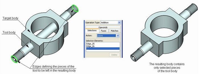
In some situations, one operand of a Boolean becomes split into several pieces. The improved Boolean now allows specifying the pieces of an operand to "keep" as the result or to "exclude" from the result.
"Bend" Operation
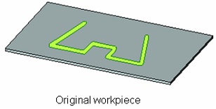
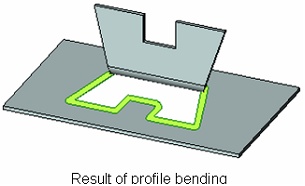
It is now possible to create a flange from an open profile. This is necessary, for example, when bending an "ear" in the interior of a surface. The base line for bending in this case is represented by the line segment connecting the start and the end of the open profile.
Blend Operations
"Blend edges" and "Blend faces" got a new option "Inside tight corners". In the areas where the curvature of side wall surfaces is greater than the curvature of the blend being created, the system may use special processing to insure blending with the specified radius in the curved zone.
· Tight blends – in this case, the system will process the curved zones using the fastest algorithm. The algorithm assumes that the surfaces in these zones are created solely by blends of constant radius. If the type of the original surface is different and the new blend cannot be created, an error is output.
|
|
Unprocessed original |
"Tight blends" processing |
· Tight faces – the system processes the curved zones, assuming, that the zone of small curvature radius fully extends through some face of a sidewall.
|
|
Unprocessed original |
"Tight faces" processing |
· Tight partial – this is the most complex, but also versatile, algorithm. It allows processing the cases, when the zone of small curvature radius covers the portion of a sidewall of the blend. In this case, the blend surface is additionally subdivided in order to provide correct processing.
|
|
Unprocessed original |
"Tight partial" processing |
Face Taper
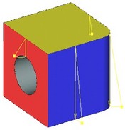
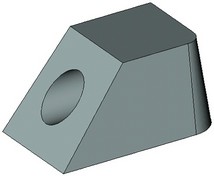
Due to the introduction of the "Body taper" operation, the former "Taper" operation is renamed to "Face taper". The new operation has friendlier interface, providing capability of specifying different taper angles for each individual selected face.
Local Coordinate Systems
The "3O" command interface has been significantly simplified without sacrificing the existing functionality. Such change became possible due to the newly introduced system capability of selecting geometrical elements (3D points, directions, planes, etc.) via various system objects. The only options currently left in the command are those for selecting a center point and additional axis orientation.
To support the constraints mechanism for 3D fragments, the permitted degrees of freedom can now be specified in the coordinate system parameters. Overall, there are six degrees of freedom: three for fixing translations, and another three for fixing rotations about coordinate system axes. Those data are passed on to properties of 3D fragments relying on such coordinate system as the origin.
3D Fragments
The "3F" command is improved, in particular, by simplifying the procedure of creating the target and source coordinate systems inline with the new interface for LCS creation. Additionally, a 3D fragment can now be inserted in an assembly as an adaptive element, for which purpose the 3D fragment creation command has been fitted with appropriate tools.
This command has also been adapted to utilizing the new constraints capability. The 3D fragments gained new properties – degrees of freedom inherited from the properties of the source LCS. If such a 3D fragment is inserted in an assembly that uses mates, then its properties will be included in calculations of the assembly's suite of constraints. 3D fragments with degrees of freedom can be dynamically moved in the command "Move Mated Elements".

The functionality and interface of the 2D projection creation command has been significantly enhanced. The command now relies on the properties window for specifying parameters, provides filter buttons in the system toolbar and offers the following new capabilities:
· The system can now automatically determine the type of the projection being created based on the first selected element (a section, a cut or local area view, a workplane, a hatch for creating a local section, another projection for creating a projection with projective relation). When creating a projection with projective relation, the latter is classified automatically by the pointer movement (top, left, right, etc.).
· A new capability is added for projecting all elements on the scene except the specified ones. This allows excluding unnecessary elements from the projection. It also became possible to project Bodies. In this way, one can create a projection of the "workpiece", and then proceed with model adjustments. Meanwhile, the projection will reflect on all changes in the Body.
· When using sections, it became possible to apply a section to all objects being projected, except specified ones.
· Broken view creation became user-friendlier. While in the mode of creating a broken view, the system determines the direction of the break automatically by the pointer movement (horizontal or vertical).
3D Dimensions on 2D Projections
2D projections gained a new parameter "Save information for 3D dimensions". With this parameter set, the dimensions based on the lines of a given projection are drawn as "spatial". In this way, they are located in the plane of the selected elements or in the plane of a round edge when dimensioning the elliptical image of that edge. This capability allows creating dimensions with correct values on axonometric views.
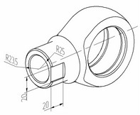
When inserting a symbol in a text, it is possible to use the option "Ignore font angle", which makes the inserted symbol displayed without slant, regardless of the font parameters used in the element in which the symbol is inserted.
Enhancements are made to the built-in text and table editor:
· A capability is added for inserting fragments of one table into another table.
· A capability is added for copying/pasting tables from T-FLEX CAD to MS Word and back.
· A capability is provided for using "Strikeout text" style.
When creating a 3D node, a new capability is introduced for creating the node as an intersection point of a 3D path or edge and a workplane.
Layer Management
Layer visibility can now be defined by a variable. This provides new additional capabilities in controlling the behavior of a parametrical document or fragment.
Creating Pictures in a Drawing
More file formats are now supported when inserting pictures. In addition to the provision for inserting BMP-format files, it is now possible to use JPEG, GIF, TIFF, DIB, PCX, TGA formats.
The functionality of creating dimension chains from one base is improved:
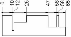
· Ordinate dimensions are now supported in the dimension creation command. Such dimensions are created from one base and do not use leader arrows.
· It also became possible to automatically line up dimension text and introduce jogs for dimension witness lines in crowded drawings.
|
|
Conventional baseline dimension |
Ordinate dimension |
Refined positioning of dimension text
A new mode is provided in the commands of creating and editing linear and angular dimensions. By cyclically switching the mode of displaying the witness line (using "Space" key), one can set the position of the dimension text without drawing the witness line. This allows the user placing a dimension text at an arbitrary position if necessary.
Copying Element Properties
A new option "Copy Properties from Existing Element" is available for creating and editing engineering drawing elements (dimensions, leader notes, GD&T formlimits). Upon calling this option, the user can select an existing element, whose properties will be copied. This mode can work together with the option "Set Properties as Default", which, when active, makes the parameters remembered and used for creating subsequent elements.
The command PM:Measure Element or relation between two Elements has been significantly changed. Parameters can now be defined in transparent mode in the properties window. Filter buttons on the system toolbar are used for selecting elements. The command works equally with 2D and 3D elements.
A new capability is added for quick replacement of an existing variable's expression with a new expression based on the current measurement.
When switching between working modes in the sketcher, the system automatically remembers the active control element in the properties window. Upon returning to this mode next time, the respective item activates automatically. For example, if the user prefers specifying a segment's length rather than point coordinates, then, upon next use of the segment creation mode, one would not have to go and activate the item in the properties window for inputting the length. The system automatically keeps track of it, letting the user to simply type the value on the keyboard.
General Changes in the System
Body Management
The new concept of a "Body" is introduced in the system as the main object of the three-dimensional model structure. A Body is a volume (or a surface) created by a base operation. In the course of modifications to this volume (surface) by subsequent local operations (blend, shell, Boolean, etc.), its "Body" remains unchanged. A Body maintains such invariant model properties as the material, color, rendering parameters (mesh density, wireframe display). A Body gets its name automatically by the system or manually by the user, which then remains unchanged throughout further modifications. Thus, the user now gets a single structure element that can later be modified by various operations-steps.
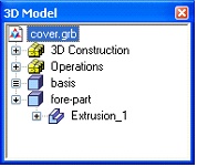
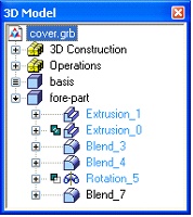
One 3D model can have an unlimited number of Bodies. Bodies are put at the root of the model structure displayed as a tree. Depending on a Body's geometry type (solid or sheet object), the respective icon is used in the model tree. A Body's history consists of a sequence of operations shaping up the Body.
The following special new commands can be executed in a Body's context menu:
· "Hide Body". This command makes a Body or a set of Bodies invisible. This property can be set in the Body's parameters dialog as well, also by using a variable.
· "Delete Body". This command allows deleting all operations and construction elements that constitute a given Body and are not used for defining geometry of other Bodies.
Bodies can be used as elements proper in some commands. For example, when creating a projection, a particular Body can be selected for projecting. This is convenient in a design flow when the drawing of a part or a set of parts is created first, and more modifications of the part(s) follow by adding new operations. The drawing in this case will reflect on all coming modifications. In the earlier versions of the system, this was achieved by projecting the whole scene or by selecting specific operations that stayed unchanged on the projection. Bodies can also be used for creating arrays and other operations.
Unicode Support
T-FLEX CAD version 9 is now relying on the Unicode encoding. This is an important enhancement due to the expansion of multilingual versions of T-FLEX CAD. Now, all documents created in T-FLEX CAD are fully portable between various Windows language versions. Besides that, one can use characters from different character sets within one document wherever textual information is entered.
New Parasolid Version
The system uses the new version of Parasolid geometry engine (http://www.ugs.com/products/open/parasolid/) – 16.1.
File Handling Enhancements
The system has been significantly improved in regard to the documents' file structure. Overall performance is increased, and a number of limitations in handling internal fragments and large three-dimensional assemblies are lifted.
"Technical Support…" Command
The new command "Help|Technical support…" is introduced in the textual menu that helps the user sending messages to the technical support via e-mail. This command automatically generates a standard message form, filling it with available data. The user just needs to enter the actual message content before sending. The message is generated from a template that can be edited by the user as desired.
The command "SO: Set System Options" allows the user to fill in some data that will be automatically carried over to the message (the user name, the company name, the license number), and to specify the name of the template file that will be used for generating the message.
API (Application Programming Interface)
T-FLEX CAD version 9 is shipped together with a completely new API (application programming interface). This API is based on .NET technology (http://www.microsoft.com/net/), offering the developer almost any possibility for managing T-FLEX CAD documents and developing applications running in T-FLEX CAD environment. With introduction of this API, T-FLEX CAD emerges as an open-end platform for developing applications getting all benefits of this parametrical modeling system.
Since the new programming interface uses .NET technology, it is free of the shortcomings of the application developing tools of the earlier system versions. This one has the following advantages:
· Fast execution of API-based applications. The execution speed is almost the same as the system performance itself.
· A provision for using various programming languages for developing applications. Currently supported are programming languages of any flavor: C++, C#, Visual Basic, Java, and more.
· A provision for using various programming environments for development: Visual Studio, Delphi, etc.
· High degree of expandability and independence from the system version. An application developed for a particular system version will continue running with future versions without required recompilation.
· A large number of classes and methods covering all aspects of managing system objects. The current API version accounts for more than 100 classes and more than 5000 methods in those classes.
· Independence from T-FLEX CAD developments. The API-based applications built on .NET do not require a special license from "Top Systems". The system is shipped with a built-in Help of API functionalities. Developing does not require any special tools, except for the T-FLEX CAD and a programming environment.
The API allows creating DLL applications that can be run in T-FLEX CAD environment, creating and managing objects of T-FLEX CAD models, using all instruments of Windows user interface. The API allows changing the behavior of objects in a T-FLEX CAD model or augmenting those with custom functions. A provision is also made for creating custom application objects with a totally new behavior. In addition, the object identification mechanism allows T-FLEX CAD objects (nodes, construction lines, 3D elements, etc.) snap to those objects.
Macro Language
T-FLEX CAD version 9 includes proprietary tools for developing macros. The center part is a macros editor that allows creating applications using classes and methods of T-FLEX CAD API, as well as any means of the operating system. The user is enabled to develop applications for managing system documents without the necessity of installing and learning third-party development tools. Macros can be developed using C# or Visual Basic programming language. In the future, this list may be extended.
Macros are saved directly in the document file. A special "Macros" tool window is introduced in the main T-FLEX CAD window, that allows launching or editing macros of the active document.
Earlier-Version Document Converter
When old documents are converted to the new format, a new capability allows automatically creating a typical set of hidden variables and data for BOM. This action is performed if such data is missing in the source file. The information is copied from prototype files: drawings use a drawing prototype, while 3D models - a 3D model prototype.
Deleting Elements
The deletion command gained extended functional capabilities that provide more flexibility in deleting objects from a model. A dialog is added with the following options:
• Delete Selected Elements and all Dependent Elements. If there are unused parent elements, those parent elements can be deleted. If there are workplanes among those, they will be deleted together with the respective pages;
• Delete only Selected Elements changing type of Dependent Elements. This functionality is available for 2D objects only. It allows excluding the object being deleted from the model structure by "tearing off" from children (dependent elements). The reference definition of the children of the deleted elements will be changed in this case;
• Exclude Selected Elements from Model Tree replacing relations to other Elements. When using this option, the system attempts to reassign the relations of the dependent elements to other model objects.
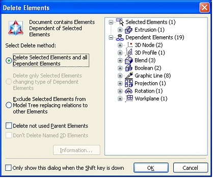
The new command "Delete Body" has the following capabilities:
• Delete Only Parent Constructions. The Body is deleted together with only those constructions and workplanes (with their respective pages), that are not used by other elements;
• Delete All Parent Elements. This deletes all parents of the Body, that are not used by other model elements;
• Don't Delete Parent Elements. Deletes only the operations constituting the Body.
The following options are added in the command "Purge…":
• Delete Unused Named 2D Elements. This does not delete 2D constructions with specified individual names;
• Current Page Only. This option works only in the drawing mode;
• Delete unused 3D Identifiers. The option shrinks the size of the 3D model, if possible.
Importing and Exporting Documents in AutoCAD Format
The new T-FLEX CAD version has a largely reworked mechanism of data exchange in AutoCAD formats. AutoCAD 2004 and 2005 file formats are now supported for both import and export. Supported also is the binary format *.DXB. When models are exported, all T-FLEX CAD drawing elements are now output (pictures, drawing views, detailing elements, area views, etc.). In model import, AutoCAD drawing views, blocks and likes are correctly handled. When importing blocks in T-FLEX CAD, internal 2D fragments are used.
Improvements to Data Exchange Translators
Quality and accuracy are improved of importing and exporting files in STEP and IGES formats. Import of assembly models in the above formats has been refined. When importing files in IGES format, it is no longer necessary to use an intermediate file in Parasolid (xmt_txt) format. Models are imported directly into the current document. In addition, importing and exporting IGES format now accounts for the color of model faces.
Changes to User Interface
"Hiding" Tool Windows
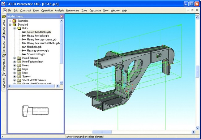
All system auxiliary windows (Properties window, 3D model structure, Bird's eye view, Model Menu window, Diagnostics window, etc.) are enabled with a new behavior. When such window is docked at a side of the main system window, there is a special button in its header (a left-pointing arrow) for shrinking the window into a compact tab. Such tabs are placed along the perimeter of the main system window. Upon pointing the mouse at such a tab and resting there briefly, the respective window automatically "unfolds" under the pointer. If the pointer crosses the boundary of the tool window, the latter automatically hides after some delay. This functionality helps to save significant workspace on the screen.
Document Icons
The mechanism of using document icons has been refined. An icon is a special file <Drawing/model name>.ico. Now, if a document has an icon, the latter is displayed anywhere this type of icons is enabled (document tags, Model Menu window, icon of a document view, file manager window or document libraries). The same icon is also displayed in the 3D model structure window in the case if the 3D fragment has it stored. This functionality makes T-FLEX CAD documents and assembly models management much more intuitive.
Now, a special module is installed as part of the system installation that is responsible for correct display of T-FLEX CAD document icons in the Windows Explorer as well.
Highlighting of Geometrical Elements
In the three-dimensional system edition, geometrical elements (normals, characteristic points, tangencies, etc.) are highlighted on the screen as the specific points, direction vectors, etc. This enhances working convenience when creating complex geometrical models.
New Capabilities of the 3D Model Structure Window
Enhancements are made to the document's 3D model structure window functionality. The model structure now allows using the icons of 3D fragments that are the icons of the documents corresponding to the respective fragments.
If the user expands a structure element, the expanded state is maintained through model regenerations and in the future working sessions with this model in the document file.
The functionality of moving three-dimensional operations around the model tree and deleting operations with exclusion from the tree are refined.
Toolbars
The toolbars that automatically appear upon entering certain commands or working modes are now enabled with the context menu that allows suppressing the automatic display of the given toolbar. Among those are the toolbars of snappings, table-editing commands, BOMs, active workplane controls, special sketch editing commands, drawing plane controls.
Multiline Text Entries
Multiline editable text entries now support use of predefined value lists. This is true for the "Line under ..." text parameter in dimensions and leader notes.
System Options
A new parameter "Load Previous Session Documents on Start" is introduced on the tab "Preferences" of the "Options" dialog. When it is set, the list of documents staying open at the time of exiting the application is stored in the registry. Upon a subsequent launch of the system, these documents will be automatically loaded.
3D View Options
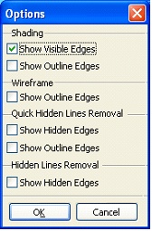
More 3D view options are introduced: outline edges can now be displayed in all modes, while the modes that hide invisible lines are now enhanced with a capability of displaying invisible lines as dotted lines. The "Hidden Lines Removal" mode is now made to persist after spinning the scene.
