Mates and Degrees of Freedom |
  
|
Mates and Degrees of Freedom |
|
In the process of designing solid assembly models in T-FLEX CAD, it is often necessary to specify mutual position of parts, which may not always be accomplished by the conventional technique of fixing by LCS adopted at T-FLEX CAD. This is due to the fact that changes in part positions may have to be reciprocal. A given part can simultaneously have multiple contacts with other movable parts. When using the approach based on LCS, recursive dependencies of references may occur in such cases (a part's dependency on itself). Such tasks may occur, for example, when building models of mechanical systems (mechanisms). To handle such tasks, mates are introduced which are the system elements that allow imposing various dependencies on the geometrical objects of two component operations (3D points, axes, curves, planes and surfaces).
A model of a mechanism designed with the use of mates can be animated in the special command, where you move its parts by the mouse.
To fix a 3D fragment using LCS, you can specify additional conditions in the way of the permitted degrees of freedom. If such a 3D fragment is later attached via an LCS to another constrained element, then it will be included in calculations of the constrained mechanism. The method of positioning the selected parts by using mates is to be used as an auxiliary way of fixing together with the use of fixing by local coordinate systems. The use of mates requires additional computational resources for evaluating solutions. Therefore, we recommend using mates in the cases when other approaches to the described tasks are not suitable for some reasons.
What is a mate?
The "Mates" tool serves for mutual attachment of assembly model elements. It allows positioning those according to the specified geometrical conditions. These conditions define the mutual situation of the three-dimensional model objects (such as faces, edges, vertices, characteristic points, axes of surfaces of revolution, etc.) with respect to each other. The system automatically resolves the specified set of mates and situates the objects in the way satisfying the specified conditions. Mates allow precisely positioning the parts of the mechanism being designed with respect to each other. Those allow to impose certain properties in a mechanism's model and determine how its components move and turn with respect to other parts. Combinations of different mates can be used for more precise definition of the restrictions on an assembly element's position with respect to another element. Relations between pairs of components are associative. If one part is moved then another part will move along. For example, if a screw is tied to a hole, then relocation of the hole will cause the screw to follow along.
Mates are imposed on pairs of geometrical objects. Those either connect two components together or fix a body to its environment (with respect to a fixed object). A fixed object is an object with all its degrees of freedom restrained or a one whose position in the space remains still. It is recommended that at least one component be fixed in the space. This creates a "ground" for all other constrained parts and can prevent an unexpected dislocation of a mechanism's components.
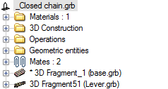
Each mate appears as a model object having its place in the model structure. As a fully functional system object, a mate has a name, working properties and is displayed in the 3D model structure. The user can turn off some of the mates in order to temporarily exclude those from the general solution. This allows experimenting with various types of mates without redefining the mechanism interdependencies.
Types of mates
When defining geometrical ties in the form of mates, you can use only the following geometrical terms: 3D point, axis, curve, plane, surface. In order to specify the geometrical data, the user selects topological elements of the model or construction elements. Use of 3D construction elements is possible under the condition that those are constructed based on an operation body. Otherwise, the second component will turn out to be bound to the still environment.
Upon fixing by construction elements, you lose the capability of dynamical articulation of the given connection in the constrained mechanism; therefore, if possible, prefer to use the model's topological elements (vertices, edges, faces, etc.)
When creating mates, make sure to understand the difference between the geometrical data used by mates and topological objects used for selection. For example, a flat face has boundaries, while the plane used in the mate is infinite. Therefore, the created geometrical relation based on a flat face will still be valid beyond the boundaries of this face.
Coincidence
This type of mate insures full coincidence of one geometrical object with another one. The number of remaining degrees of freedom depends on the geometrical type of the objects being joined. For example, aligning two points will create a spherical joint that blocks any translation while allowing any rotation. Aligning a point and a curve will allow elements to rotate, and also to slide along the curve. The following table shows the possible combinations of geometrical elements when using the coincidence:
Coincidence |
Point |
Axis |
Curve (except circle) |
Circle |
Surface (except conical surface) |
Conical surface |
Plane |
Wire body |
Sheet body |
Solid body |
Point |
+ |
+ |
+ |
+ |
+ |
+ |
+ |
+ |
+ |
+ |
Axis |
+ |
- |
- |
- |
- |
- |
+ |
- |
- |
- |
Plane |
+ |
+ |
- |
- |
- |
- |
+ |
- |
- |
- |
Circle |
- |
- |
- |
- |
- |
+ |
- |
- |
- |
- |
Conical surface |
- |
- |
- |
+ |
- |
- |
- |
- |
- |
- |
A point can be aligned to any geometrical object. If two flat faces are selected, those will lie in one plane. Coincidence of an axis and a plane will insure the axis' placement on the plane of a flat face. The condition of coincidence between a point and a solid insures the point's placement being maintained on the solid's surface.
Upon selecting a circle and a conical surface, matching of the selected surface and the circle is realized in such a way that the plane of the circle is perpendicular to the axis of the cone.
Using the coincidence in combination with other types of mates allows imitating various mechanical connections. For example, coincidence of a pair of 3D points provides for a spherical joint.
Parallelism, perpendicularity
These types of mates represent a special case of the "angle" mate type. These insure mutual parallelism and perpendicularity of the selected geometrical objects. The following table presents the possible combinations of geometrical elements when creating parallelism or perpendicularity mates:
Parallelism, Perpendicularity |
Point |
Axis |
Curve |
Surface |
Plane |
Wire body |
Sheet body |
Solid body |
Axis |
- |
+ |
- |
- |
- |
- |
- |
- |
Plane |
- |
+ |
- |
- |
+ |
- |
- |
- |
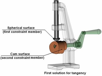
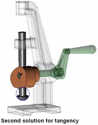
Tangency
Tangency insures a constant physical contact between two geometrical objects. Depending on the geometry type of the interacting objects, a contact may be occurring in one point (example: a plane and a sphere) or along a line (a plane and a cylinder). This type of mate can be set between two planes, a plane and a surface, two surfaces. Tangency between an arbitrary body and a surface works only for a spherical surface.
Tangency |
Point |
Axis |
Curve |
Surface |
Plane |
Wire body |
Sheet body |
Solid body |
Surface |
- |
- |
- |
+ |
+ |
+ |
+ |
+ |
Plane |
- |
- |
- |
+ |
+ |
+ |
+ |
+ |
Sometimes, there are several possible solutions to connecting the selected objects. For example, if a plane and a sphere are selected, then the solution yields two tangency points. In the case of a non-unique solution, the system makes a decision automatically. Normally, the nearest point to the current location of the mechanism is accepted as the solution. To transit to another solution domain attainable by the moving mechanism, use the "dragging" motion mode (see below).
In the case of a non-unique solution, it is recommended to bring the components being constrained into the area of the desired result before creating the mate. Parts of a constrained mechanism can be moved within the command "Move Mated Components". The components that were not yet subjected to mates, can be moved by using the command "Transformation".
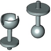
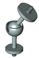
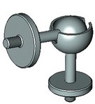
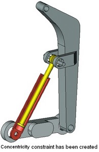
Concentricity
"Concentricity" is a special case of the "coincidence" mate type. It insures coincidence of two axes. This type of mate is a most commonly used one. Normally, this mate type is engaged in combination with other types. For example, to snap a part with an axis to a hole, coincidence (of flat end faces) is used quite often in combination with concentricity. To define concentricity, one can select model elements suitable for defining an axis (surfaces of revolution, elliptical edges, straight edges, etc.).
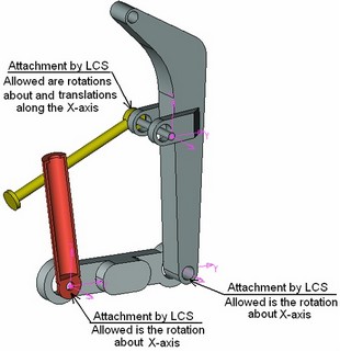
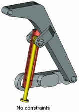
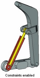
The diagrams show constraining parts of a schematic hydraulic cylinder by concentricity. Other parts of the simple mechanism arc connected by local coordinate systems. For viewing convenience, some parts of the mechanism are sectioned along the axis.
Distance
The "Distance" mate defines a relation between two objects by fulfilling the condition of maintaining a specified distance between two geometrical objects. One can specify the conditions of types "no greater than", "no less than" or "equal" to the specified value.
The following table presents the possible combinations of geometrical elements when creating the "distance" mate:
Distance |
Point |
Axis |
Curve |
Surface |
Plane |
Wire body |
Sheet body |
Solid body |
Point |
+ |
+ |
+ |
+ |
+ |
+ |
+ |
+ |
Axis |
+ |
+ |
- |
- |
+ |
- |
- |
- |
Surface |
+ |
- |
- |
+ |
- |
- |
- |
- |
Plane |
+ |
+ |
- |
+ |
+ |
- |
- |
- |
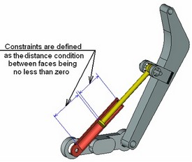
This type of mate can be used, for example, for defining an object's shift or for restricting mutual penetration of faces. To define a restriction on mutual penetration of faces of different parts, you just need to specify the distance condition "no less than" zero. This can be used for mechanisms whose operation relies on physical contact (collision) of its parts.
Continuing with the hydraulic cylinder example, let us show how to use the "distance" mate. The mechanism created at the previous step will operate incorrectly in certain motions, because some parts of the hydraulic cylinder may penetrate each other. This problem is resolved by the "distance" mate. One can specify the condition that the distance between the respective faces of the piston and the cylinder must be greater than or equal to zero. When mates are dragged kinematically, this will yield the correct representation of the mechanism's behavior.
Angle
This mate defines angular distance between two geometrical objects. The turn angle can be used for rotating a component referencing the desired position. Just as in the "distance" case, this mate type supports use of conditions. When defining such connection, normally there are two or more solutions.
The following table shows the possible combinations of geometrical elements when creating the "angle" mate:
Angle |
Point |
Axis |
Curve |
Surface |
Plane |
Wire body |
Sheet body |
Solid body |
Axis |
- |
+ |
- |
- |
+ |
- |
- |
- |
Plane |
- |
+ |
- |
- |
+ |
- |
- |
- |
«Gear-Gear» Transmission
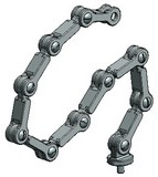
This type of mate serves for creating conditions for the interaction of two bodies spinning about their respective axes. The conditions are specified as a transmission ratio between two spinning objects, that is, the number of revolutions made by one of the components while turning the other one. Upon introducing such a mate, a two-sided relation is formed. This type of mate is convenient for monitoring mechanisms that incorporate dented wheel or belt drives.
Remember that this type of transmission relation, just like any other transmission mate, merely tells the system the mutual ratio of angular (in this context) velocities. Also note that each component must be fully fixed in its place by the time of creating a transmission mate and be assigned all required degrees of freedom and constraints.
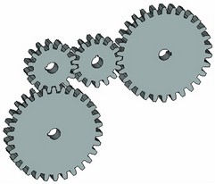
To create such a mate, select two axes of revolution and specify the transmission ratio. In this case, the shape of the dented wheel is not significant for the system, as the wheel dents can be created for «cosmetic» purpose only. The law of the mechanism's movement will be defined solely by the mate conditions.
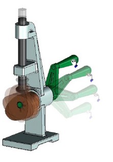
«Gear-Rack» Transmission
This type of mate serves for creating the conditions for two interacting bodies, in which one component spins, while the other one moves about one or multiple axes. This type of mate allows modeling, for instance, a nut being picked up by a screw, a transmission link of the type «pinion-rack», etc. The mate conditions are defined as the amount of the distance traveled by the movable component along the specified axis while the other component makes one full turn. A two-directional relation results from creating this kind of mate.
To create a mate, you need to define the axis for each of the two components and specify the distance in the model units that one component would travel while the other component rotates by 360 degrees. The first one defines the «pinion» axis, the second one - the «rack» axis.
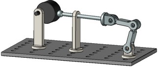
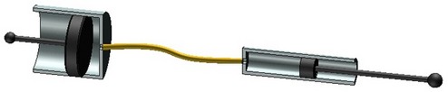
«Linear Movement» Transmission
If there are two objects in the model moving in their respective axial directions, then you can specify a ratio using the mate being described, that would characterize the mutual displacement of the two objects. With such a relation established, the travel distance of the second component will be calculated by multiplying the first component's travel by the specified ratio. The relation can work in the reverse direction as well (from the second component to the first one); in this case, the system will use the ratio which is the reciprocal of the specified one. This type of mate helps modeling the mechanisms representing systems of pulleys, hydraulic mechanisms, etc.
To create a mate, you need to define the axes for each of the two components, and enter the value of the velocities ratio of the moving components in the provided input box.
Attaching 3D fragment by LCS
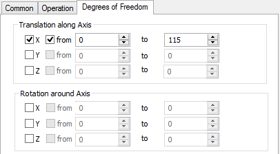
A 3D fragment inserted in an assembly using local coordinate systems can also be involved in a 3D model built on mates. To define a 3D fragment's behavior with respect to the fixing LCS, the permitted degrees of freedom are specified in the fragment's parameters. There are total of 6 DOF's – distributed as 3 for translations and as many for rotations with respect to LCS axes. An additional limit can be set for each DOF as a range of values.
One can also specify the degrees of freedom in the parameters of the source LCS in advance, in the fragment's file. Upon inserting a 3D fragment, the conditions are copied from LCS parameters to the parameters of the 3D fragment together with the degrees of freedom and are later accounted for when calculating the mates complex of the developed 3D assembly model.
If the target LCS was not specified at the time of creating a 3D fragment, making the fragment attached "by default", the degrees of freedom management mechanism will not be applicable to such fragment.
When designing complete assemblies of mechanisms using the degrees of freedom and mates, it is important to account for the following point. A 3D fragment being inserted in an assembly by fixing to an LCS may or may not be related to some assembly component. In the latter case, the component behavior may not agree with the expectancy as other assembly components are moved. For example, it may stay still while its surrounding parts move, or, vice versa, moving it may not induce motion in the neighboring parts.
To have a 3D fragment be related with another component, its target fixing LCS must be built on geometrical objects of that component. Otherwise, it will be attached to the still environment.
The so-called "Aggregate" mechanism is introduced in the system for creating complex assemblies. This mechanism allows creating mates in the model of the 3D fragment first, so that those are automatically accounted for when such a 3D fragment acts in an assembly.
Creating mates
To create a mate, use the command:
Icon |
Ribbon |
|---|---|
|
Assembly → Mates → New |
Keyboard |
Textual Menu |
<3CT> |
Tools > Mate > Create Mate |
To create a new mate, complete the following steps:
1. Select the mate type.
2. Select the first object.
3. Select the second object.
4. Define parameters of the selected mate type (if necessary).
5. Confirm the selections.
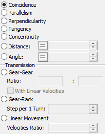
Selecting mate type
A mate type selection is done in the properties window. To make a selection, set the radio switch into the desired state. For "Distance" and "Angle" mates, one can define a condition with respect to the specified value. Pressing the button before the numerical value cyclically switches its condition sign. For transmission mates, the numerical parameters are defined in the respective input boxes.
Selecting mate elements
The modes of selecting the first and second geometrical objects are engaged by the following options:
![]() <F> Select first element
<F> Select first element
![]() <S> Select second element
<S> Select second element
Upon selecting the first element, the system automatically turns on the option for selecting the second element. If it is necessary to return to defining the first element, turn on the respective mode manually.
Depending on the type of the mate being created, different geometrical objects can be selected. Tuning the selection to the desired type of geometrical data is done by the automenu options:
![]() <V> Select point
<V> Select point
![]() <A> Select axis
<A> Select axis
![]() <C> Select curve
<C> Select curve
![]() <U> Select surface
<U> Select surface
![]() <L> Select plane
<L> Select plane
![]() <W> Select wire body
<W> Select wire body
![]() <H> Select sheet body
<H> Select sheet body
![]() <B> Select solid body
<B> Select solid body
For some mates, a number of options may be unavailable or temporarily inaccessible (see the tables of combinations above). Each option turns on a set of filters for selecting objects suitable for defining the required geometrical element.
Selected objects are highlighted. Also highlighted are the operations whose geometrical elements are selected. Simultaneously, the system offers a preliminary choice of solving the mate. According with this, the system moves the elements as to fulfill the mate conditions. If one or both elements already have mates with other bodies or fixed still to the environment, then the new solution is calculated by accounting for all earlier imposed restrictions.
Fixing mate member
When creating a mate, one of the two mate members can be fixed in the space. Fixing is done by pressing the button marked by an anchor image, in the properties window. Upon fixing, the object becomes "frozen" in the 3D space in its current position. It will neither be affected by any new transformations nor by changes in parameters of existing translations. The "*" mark will appear before the name of the fixed operation in the model tree.
![]()
Repressing ![]() button cancels fixing of the mate component.
button cancels fixing of the mate component.
It is also possible to fix a body in space outside the command of mate creation. Use “Fix Component” from the context menu of any body (![]() icon) if the current 3D assembly contains any mates or uses degrees of freedom for 3D fragments.
icon) if the current 3D assembly contains any mates or uses degrees of freedom for 3D fragments.
The command “Fix Component” is always available in the context menu of the fixed component. The icon corresponding to this command is pressed if a component is fixed. Applying this command will disable fixing in this case.
Selecting elements for defining transmission ratios
You need to specify numerical parameters (transmission ratios) when defining transmission mates. An additional capability is provided in the cases of «Gear (angular speeds)» or «Worm (pinion-rack)», which is using geometry of the mated elements to automatically determine the numerical transmission ratio. The options for defining the transmission ratio appear automatically in an additional section of the automenu when selecting the appropriate mate type.
The transmission ratio for the «gear» transmission is calculated as the ratio of the two selected elements' radii. The following options are used in the automenu:
![]() <G> Select first element to define transmission ratio
<G> Select first element to define transmission ratio
![]() <D> Select second element to define transmission ratio
<D> Select second element to define transmission ratio
![]() <Z> Cancel transmission ratio selection
<Z> Cancel transmission ratio selection
In the case of the «Worm» mate, the transmission ratio is calculated based on the connecting thread parameters. The following options are used in the automenu:
![]() <T> Select threaded face to define transmission ratio
<T> Select threaded face to define transmission ratio
![]() <R> Select edge or face to define transmission ratio
<R> Select edge or face to define transmission ratio
![]() <Z> Cancel transmission ratio selection
<Z> Cancel transmission ratio selection
Additional mate parameters
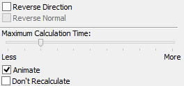
Reverse Direction. This option rotates the second (or the remaining movable) component being connected by a 180 degrees or moves it into another solution domain. For the transmission mates, this parameter alters the direction of the second component motion.
Reverse Normal. This option works only with the "distance"-type mate between two planes. In addition to the previous option, it allows changing the direction of counting the distance.
Maximum Calculation Time is the parameter controlling the number of passes the system is allowed to use in search for the solution with the specified precision. This limitation is necessary to avoid too long system computations due to an accidental user error, that are possible when searching for solutions in complicated cases. This parameter is set by a slider.
If no solution was found after the current number of iterations, try to increase the allotment. On the other hand, it could be sufficient instead to manually move the components being connected toward the probable solution domain in the command "Move Coinstraint Operations" (see below).
Animate – this parameter lets the system gradually relocate the elements being constrained in order to examine the mate solution behavior.
Don't Recalculate – this parameter suppresses mates calculation at the time of creation. This capability can be used in order to save time when working with large assemblies. This could be useful, for instance, when the user adds several mates one after another. To search for a solution, you will need to do full model recalculation. In this case, note that upon adding several complex mates or simply a too large number of mates, the system might not finally find the correct solution (see the topic «Processing possible erroneous cases while working with mates» below).