Techniques of Handling Existing Mates |
  
|
Techniques of Handling Existing Mates |
|
Working with model tree
The created mates are displayed in the "3D model" window. Most of manipulations with existing mates are done via this tool window. A special folder is created in the model tree, in which the system automatically puts all mates. An icon is provided for each mate type that corresponds to the type. Each mate is preceded by the mark ![]() . Clicking it by
. Clicking it by ![]() will show the objects in the expanding branch of the model tree, on which the mate is based. Mates can be additionally grouped in subfolders.
will show the objects in the expanding branch of the model tree, on which the mate is based. Mates can be additionally grouped in subfolders.
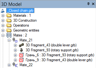
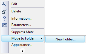
However, only one subfolders nesting level is supported. All mate subfolders are marked with the icon ![]() . Each additional folder has a unique name. Grouping by additional folders doesn't affect anything. This is done merely for working convenience when sorting out a large number of mates. To move a mate to another folder, use the context menu item "Move to folder". The new submenu makes available the commands for creating a new additional mates folder and moving to the main and already existing additional folders. The rest of commands in this context menu are common across various system elements ("Parameters", "Edit", "Delete", "Information…").
. Each additional folder has a unique name. Grouping by additional folders doesn't affect anything. This is done merely for working convenience when sorting out a large number of mates. To move a mate to another folder, use the context menu item "Move to folder". The new submenu makes available the commands for creating a new additional mates folder and moving to the main and already existing additional folders. The rest of commands in this context menu are common across various system elements ("Parameters", "Edit", "Delete", "Information…").
Suppressing mates
Any mate can be suppressed. The command for suppressing a mate and canceling the suppression is accessed in the context menu by right clicking ![]() a mate. It is also possible to impose suppression on a group of mates at once by accessing the command from the context menu on right clicking the mates folder. A suppressed mate is marked with a blue cross in the model tree and is excluded from calculating mates.
a mate. It is also possible to impose suppression on a group of mates at once by accessing the command from the context menu on right clicking the mates folder. A suppressed mate is marked with a blue cross in the model tree and is excluded from calculating mates.
Mechanism motion
To dynamically view the motion of a composed mechanism, use the command:
Icon |
Ribbon |
|---|---|
|
Assembly → Mates → Move |
Keyboard |
Textual Menu |
<3CM> |
Tools > Mate > Move Mated Components |
Upon calling the command, you are required to select the desired part of the mechanism for defining motion. Motion is defined by dragging the selected part by the mouse. In this way, the user stimulates an influence on the mechanism as if a force is applied to the selected point on the part in the direction of the mouse pointer in the screen plane. The part of the mechanism starts moving under the influence of the force. The motion is restricted by the specified mates with other parts and the outer environment. The selected part pulls another one, and so on, until the whole mechanism is involved in motion. In this simulation, masses and moments of inertia of the moved components are correctly accounted for.
Any translation and rotation parameters of mated (constrained) objects are recorded in the properties of each mate operation. A special transformation type, namely, "Mating transformation", is created within the operation's parameters. All quantifiable properties of this transformation are automatically calculated by the system.
Several important considerations shall be kept in mind when moving mated elements:
1. Exact numerical parameters cannot be specified for a translation.
2. Upon completing the translation command with ![]() , the parts cannot be brought back in the exact previous state. If urged, this can be done only by undoing the steps in the current session.
, the parts cannot be brought back in the exact previous state. If urged, this can be done only by undoing the steps in the current session.
3. When moving the model of the mechanism for which an assembly drawing was furnished, there is a danger of irreversible changes to the original drawing created by projecting. This could happen after refreshing the projection, due to the new positioning of the assembly parts and complications on the way of the exact rollback to the previous state of part positions.
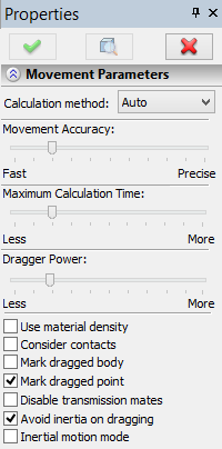
The setup of the motion modes is done in the properties window.
Number of Elements: Maximal/Minimal. When moving constrained elements, it is possible to involve all parts of the composed mechanism or just the minimal chain of mates. “Calculation method”. Sets one of two available methods of calculation – precise or fast. The precise method is used for systems consisting up to several tens of joints. The higher the complexity of system, the slower it will run the calculation. For systems including hundreds of joints this calculation may work unsatisfactory slow. In this case you need to use the fast method that works with both large and small systems. The auto mode allows system to choose calculation method itself, according to the complexity of the system. The mode of the kinematic dragger is used for moving parts in a mechanism. This results in smooth motion. It is a simulation of the effect of applying a force at the point at which the user pulls the part. The motion is generated by accounting for all specified restrictions. As the boundary of the solution domain is reached, the mechanism stops. Movement accuracy. This allows reducing the level of calculation precision for faster calculations and for maintaining the constraining conditions during a mechanism's motion. Dragger power. This setting adjusts the degree of the mouse impact on the dragging point of the body. This setting controls the applied force and, therefore, how fast the dragged parts will move after the mouse. Maximum calculation time. Sets the number of computational passes allowed to the system for reaching the required computational accuracy during the motion. |
|
Use material density. For more precise simulation of mechanism motion, a provision is made for accounting for the actual density when calculating mass properties of its parts. Otherwise, the density is assumed the same for all components.
Consider contacts. To improve accuracy of movement simulation there is an opportunity to consider the intersection of objects.
Mark dragged Body. This is an auxiliary parameter for switching On/Off highlighting of the mechanism part being pulled at the user for inducing the motion.
Mark dragged Point. This parameter turns on highlighting of the point which is pulled by the mouse pointer. The point is marked by a cross. This functionality can be used when the body highlight is off.
Disable transmission mates. This option allows disabling transmission mates. Such a capability is convenient for bringing transmission members to the starting mutual configuration (for example, the correct interlocking of wheel dents).
Avoid inertia of dragging. This parameter allows to switch on/off the consideration of the body inertia.
Inertial motion mode. This parameter allows to consider the inertia without its fading over time.
There is a simplified way to change 3D element position in space within the specified degrees of freedom. For activation of this opportunity you need to select the body in the scene using the filter |
|
Optimum length of chain of mates
As a mechanism is being created, one part gets "hooked up" to the outer environment, while other parts are linked to each other via mates. In this way, a number of parts subsequently linked to each other can be viewed as a chain of mates. If several parts all connect to one part, the chain of mates forks. When creating mechanisms, pursue the shortest chains possible. Shorter chains are solved faster, and fewer computational errors occur on the way.
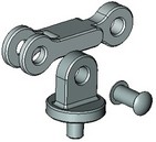
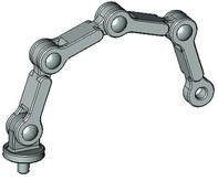
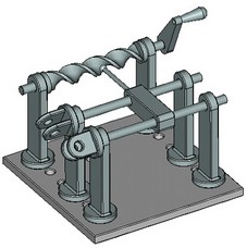
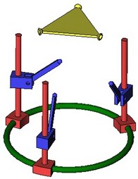
Let's review the following typical example – suppose, we need to create a model of a simple mechanism shown on the diagram. The mechanism represents a joint-type connection, joining together three parts – a support, a lever and an axis. The most rational approach in this case will be creating two short chains of mates, rather than one long.
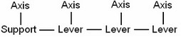
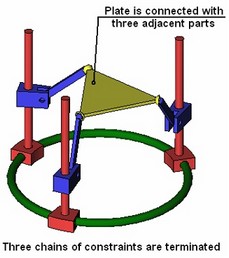
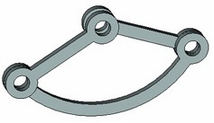
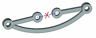
The lever needs to be attached to the support first, using concentricity and coincident flat faces mates. The axis can be attached to any of the parts as well, such as the support, by concentricity and coincidence. This results in two chains of mates: support-lever and support-axis. In this case, it would not be rational to attach, for instance, the axis to the support, and then the lever to the axis, since that would result in a longer chain of mates "support-axis-lever".
|
|
|
Sample mechanism |
Parts of mechanism |
Advancing mechanism (adding new mates) |
|
|
Rational chain |
Undesirable chain |
Naturally, this simple example will not exhibit any noticeable slowdown in the system performance; however, the difference becomes substantial in more complex cases.
Recommendations on combined use of fixing by LCS and mates
In this section, we review the recommended rules of combined use of mates and fixing by LCS when creating assemblies. Fixing parts by mates shall mainly be used together with fixing by LCS. Note also that priority shall be given to the traditional way – fixing fragments by coordinate systems. This approach has a number of advantages over mates.
Firstly, some types of geometrical relations, including the most commonly used (as a single-axis joint), can be solved by one LCS, while in the mate approach it may require bundling two or more mates. In particular, a single-axis joint is defined by two mates (concentricity + coincidence of end faces), or just one LCS (with rotation allowed about one axis). This main advantage has more consequences:
· Overall, the system works faster (the chain of mates becomes shorter, computational errors are reduced, calculations become simpler).
· A simpler model structure results from avoiding extra elements (the mates).
· The model becomes more robust to topological changes (due to minimized use of topological body elements).
So then, when the use of mates is justified? To answer this question, let's review the process of designing an assembly. In regard to the posed question, the designer typically faces 2 tasks.
Task 1: creating an assembly model without a provision for a "movable" mechanism. The user knows in advance what he is developing, and that his model will not have to move upon assembling, that's unnecessary. For example, if we are designing a TV set or a house, it is unlikely that we will need to "animate" those dynamically.
When the user faces such a requirement, then the single main concern of assembling parts is – how to correctly position a part within an assembly. The most effective solution is achieved by the "traditional" approach – inserting 3D fragments using LCS. In addition to overall advantages of this approach, fewer actions are required from the user. A 3D fragment insertion technique takes less time because fewer elements need to be defined, specifically:
1. The source LCS (the selection can be automatic).
2. The fixing position (selection of the target LCS or a geometry unit for its creation is done in the 3D window).
Meanwhile, each new mates would require defining geometrical data for two components, while exact positioning of a component usually requires creation of several mates.
Resort to the use of mates:
●in complex cases of geometrical interactions;
●when assembling a part that is in contact with other parts at several locations.
Task 2: building an assembly with a provision for "animating" the developed mechanism in the command for moving constrained elements. In this case, all parts of the assembled mechanism ought to interact correctly with each other. All movable parts shall necessarily have descriptions of the required conditions for calculating the mates arrangement while the mechanism is in motion.
In such a case, we recommend holding on to the rules described below.
●For the parts that are not supposed to change their position with respect to the elements they are attached to, we recommend using LCS with no degrees of freedom. For example, a nut fastened to a bolt shall always be with the bolt and shall not move with respect to the bolt.
●For the parts with varying mutual situation, first use LCS providing degrees of freedom. This will benefit in all main aspects (see above).
●Mates are used for fixing parts in the following cases:
●For parts with complex geometrical associations.
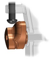
Example of complex interaction
(helical surface and pushing rod)
●For parts having more than one contact with several movable adjacent parts.
●For terminating chains of mates. In this way, each chain can be created using an LCS with degrees of freedom.
●
●For defining various restrictions, such as a restriction for mutual part penetration. For an example, refer to the hydraulic cylinder where the restriction is specified in the form of the condition "distance=0" (see the topic "Types of mates" above)
Processing possible erroneous cases while working with mates
Errors in mates might occur at various stages of handling the model. The system may not always output the detailed reason for such failures; therefore, we will list here the most common erroneous situations and typical techniques of correcting those. All erroneous situations can be divided into two types – errors occurring at a mate creation, and errors occurring in mates during model recalculation.
The problems occurring at the time of creating mates could be due to two reasons. Firstly, a mate solution may not be found as it simply does not exist. For example, this may happen when the previously imposed geometrical relations in the model are such, that the system cannot relocate the selected components to satisfy the new conditions. In such a case, you need to check up the model. It is possible that excessive, unnecessary relations are present somewhere. If that's the reason, then you could try freeing up some system components or relieve extra geometrical relations. This may often be achieved by suppressing (and later deleting) a certain «obstacle» mate or allowing an additional degree of freedom in the parameters of the respective 3D fragment. Secondly, it could be so that a theoretical solution exists but the system fails to find it. There could be several reasons for that – either too short maximum calculation time is specified, or the system cannot find the solution with the current model components configuration. In such cases, there are combinations of measures helping the system to find the solution. First of all, you could defined the longer maximum calculation time to allow the system run more calculations. Also, before creating a new mate, you should manually move the components of the mechanism to the expected solution area (by using the command of moving mated elements). This would help the system to find the desired solution in complicated cases.
A separate reason for a failure to review is when the user attempts to specify such relations that lead to recursion (self-dependency). Suppose, for example, that two components were initially fixed by LCS. Later, the user wants to impose an additional mate between two components. Meanwhile, the LCS axis of one of the components relies on geometry of the second component for orientation. Moving the second component leads to a change in the first component's position. Satisfying the mate conditions implies that both components move. In such a recursive situation, the system will never be able to find a solution. To escape the trap, you would need to exterminate the reason of the recursion – which in this case means redefining the LCS of the first component to make it independent of the second component.
Errors may occur on an initially correct model after performing the regeneration operation. Mates are calculated by groups (chains). Should an error occur in a group, each mate in this group is marked in the model tree by a red cross. The reasons for regeneration errors could be of two types. It could be so that the model underwent such changes due to which the solution satisfying all conditions is no longer feasible, or the relation between mates and component geometry is broken (as, for example, a missing topology element that was used in a mate). In such a case, restoration of mates is possible under the condition that the parent elements are restored. Otherwise, the mate needs to be redefined.
Another example is a correct model yet the system faling to find the desired solution. This may happen, for example, due to insufficient allotted maximum calculation time. Another reason could be the model getting into a trap from which the system cannot escape. In such a case, you could first try to suppress all erroneous mates, and then one by one reenable them in the model. Simultaneously with that, you could move the components to help the system find the solution. It could also be helpful in such a case to extend the maximum calculation time. This can be done with “Time” flag on the “3D” tab of the “ST: Set Document Parameters” command.