General Information
To specify the values for external variables of a 3D model, the user-defined manipulators can be created.
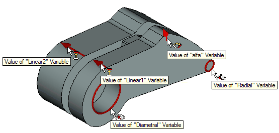
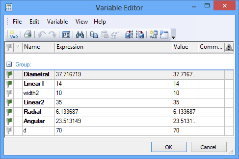
Manipulators of external variables can be used in two ways:
●to change parameters of the model in the scene. The command for controlling visibility of manipulators in the scene – «Show/hide manipulators» is added to the object visibility control toolbar in the scene.
●to change external variables values on the fragment when inserting the model into the assembly.
To create manipulators it is required that the current 3D model have external variables that control parameters of the given model.
Creating manipulator
The “Parameters|Manipulators” command allows us to create and edit manipulators of external variables:
Icon |
Ribbon |
|---|---|
|
Parameters → Tools → Manipulators |
Keyboard |
Textual Menu |
<3CV> |
Parameters > Manipulators |
In this command it is possible to add new manipulators, remove existing ones, change manipulator’s description. Creation of the following types of manipulators is possible:
●linear manipulator – arrow the length of which is equal to the variable’s value;
●radial manipulator – ring the radius of which is equal to the variable’s value;
●diametrical – ring whose diameter is equal to the variable’s value;
●angular manipulator by three points and angular manipulator by axis and initial point – a segment of a circle whose angular dimension is specified in degrees and equal to the variable’s value;
●list – for external variable the list of admissible values is available. The list can be tied to an arbitrary point on a 3D model. Manipulator of this type is shown as a small ball and upon pressing on this ball the list for variable’s value selection will appear.
When calling the “Parameters|Manipulators” command the list of already existing in the given document manipulators is displayed in the properties window. If there are no manipulators in the document yet, the list will be empty.
Manipulators already created in the document are displayed in 3D window with a grey color. In order to edit the parameters of already existing manipulator, it is required to select it – with the help of ![]() in 3D window or in the list of the properties window. The selected manipulator is highlighted in 3D window with a color (by default – red color).
in 3D window or in the list of the properties window. The selected manipulator is highlighted in 3D window with a color (by default – red color).
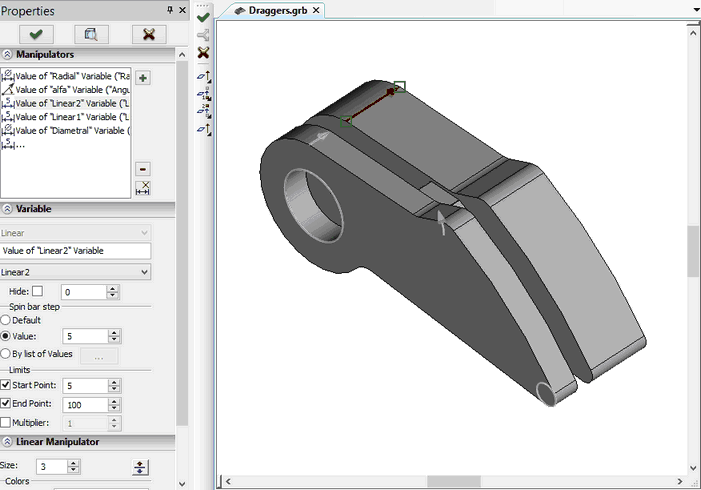
To create a manipulator ,the cursor has to be placed over the line Section “Variable”: List for manipulator’s type selection: Linear, Radial, Diametrical, Angular by three points, Angular by axis and initial point, List. Field for specifying the manipulator’s name. The name (text string) can be typed manually. Also it can be specified automatically based on the name of external variable with which the given manipulator will be linked. For this case, it is required to leave the field empty. After selection of the variable from the list below, the system itself will fill in this field according to the format “Variable’s value “Variable_name””. List of external variables of document – allows us to indicate the external variable whose value will be controlled by the manipulator being created. Hide. This flag allows us to control manipulator’s visibility on the screen. As a value for this parameter it is possible to use the real variable. Manipulator will be hidden if the value of the variable is not equal to zero. Parameters of the “Scroll step” group specify the step with which the manipulator’s value changes: By default – the step is selected automatically depending on the scene’s scale; Value (the user can specify the exact value for the step); By list of values (the list is generated by the user). |
|
Parameters of the “Range” group specify the limits for the change in the manipulator’s value and scale:
Limit at the beginning. This parameter allows us to specify the minimum admissible value of the manipulator;
Limit at the end. This parameter allows us to specify the maximum admissible value of the manipulator;
Multiplier. With the help of this parameter the coefficient by which the manipulator’s value will be multiplied can be specified.
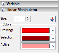
Also in the command’s properties window there is additional section with the manipulator’s visualization parameters:
Size. Size of the manipulator in 3D scene. This parameter affects only the manipulator’s visualization;
Colors/Draw. The color with which nonactive manipulators will be drawn in 3D scene;
Colors/Selection. The color with which the manipulator will be drawn in 3D scene when the cursor comes near the manipulator;
Colors/Active. The color with which the active manipulator will be drawn in 3D scene;
Radius from a point. This parameter is available only for the angular manipulator and specifies the radius of the manipulator’s arc. By default this flag is enabled, the radius is determined automatically by the points specified by the user (when defining manipulator’s geometry). When this flag is disabled, the radius value can be specified manually.
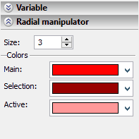
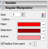
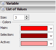
Geometrical parameters of the manipulator are specified with the help of the options of the automenu. The set of these options is different for each type of the manipulator.
For a linear manipulator the following options are available:
|
<A> |
Select axis of manipulator |
|
<F> |
Select start point of manipulator |
|
<S> |
Select end point of manipulator |
These options allow us to specify the image of the manipulator in 3D scene by two ways – either to specify the initial and final points of the manipulator’s vector or to select a 3D object that is capable of defining the manipulator’s vector.
For radial and diametrical manipulators:
|
<A> |
Select axis of manipulator |
|
<F> |
Select start point of manipulator |
|
<S> |
Select end point of manipulator |
These options allow us to specify the axis of the circular manipulator either by specifying two points or by selection of a 3D object capable of defining the axis entirely. The radius of the manipulator will correspond to the value of the variable linked with the manipulator.
For angular manipulator by three points:
|
<1> |
Specify first point of arc |
|
<2> |
Specify second point of arc |
|
<3> |
Specify third point of arc |
The arc of the angular manipulator of the given type is determined by three points: central point of an arc (selected with the help of the ![]() option), initial point of the arc (the
option), initial point of the arc (the ![]() option) and final point of the arc (the
option) and final point of the arc (the ![]() option).
option).
For angular manipulator by axis and initial point:
|
<A> |
Select axis of manipulator |
|
<F> |
Select start point of manipulator |
|
<S> |
Select end point of manipulator |
|
<B> |
Select initial point of rotation |
For the angular manipulator of the given type it is required to specify the manipulator’s arc axis – by selection of two points (the ![]() and
and ![]() options) or one 3D object (the
options) or one 3D object (the ![]() option). After the axis has been specified the initial point of the manipulator’s arc must be specified. The arc length will be determined by the system automatically based on the value of the variable linked with the manipulator.
option). After the axis has been specified the initial point of the manipulator’s arc must be specified. The arc length will be determined by the system automatically based on the value of the variable linked with the manipulator.
For manipulator of the type “List”:
|
<B> |
Select point |
This option allows us to indicate a 3D point in which manipulator in the form of a small ball will be created.
To complete creation/editing of the manipulator it is required to press ![]() after all parameters have been specified.
after all parameters have been specified.
Using manipulators
When using manipulators, i.e., when changing the values of the variables of the model with the help of the manipulators, additional control element appears in the system toolbar – for specifying precise numeric value of the manipulator.
![]()
![]()
Manipulators created in 3D model are displayed in the scene of the original document. If necessary, they can be turned off with the help of the “3SM: Turn off manipulators” command. This command is available on the “View” toolbar:
Icon |
Ribbon |
|---|---|
|
View Toolbar → Turn off manipulators |
Keyboard |
Textual Menu |
<3SM> |
|