3D Model Window |
  
|
3D Model Window |
|
To open the 3D model tree window use the command
Icon |
Ribbon |
|---|---|
|
View → Window → Tool Windows → 3D Model Tree Window |
Keyboard |
Textual Menu |
<Alt+3> |
Customize > Tool Windows > 3D Model Tree Window |
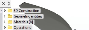
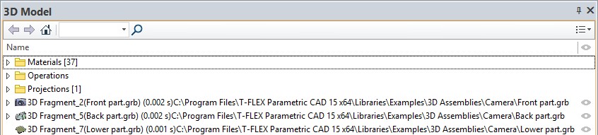
The window titled "3D Model" will appear at the left side of the screen. This tool window reflects the structure of the 3D model as a tree.
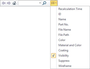
The toolbar in the upper part of the 3D Model window includes: options for window status switching, a drop-down list of columns and a search field.
![]()
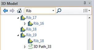
A search field allows to find an element in the 3D model tree by its name or part of the name. Elements, which names match the required name, will be displayed in the tree after searching.
Columns allows to change elements parameters and to receive information. You can change parameters for several elements at once.
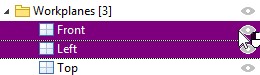
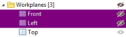
For example, if you want to hide several workplanes, it is necessary to select the planes and press ![]() in the visibility column.
in the visibility column.
If any parameter can’t be changed, its symbol will not appear in the column.
The drop-down list is used to select columns:
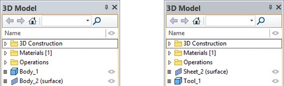
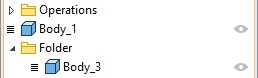
Bodies are put at the root of the model tree. Depending on the Body geometry type (solid or sheet object), the respective icon will be used for it in the model tree.
Each model Body is assigned a unique name, by default composed of the word “Body” and a number, for example, “Body_1”. If desired, any Body can be assigned an arbitrary individual name in the Body parameters.
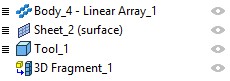
The 3D Fragment, Part and 3D Array creation operations can be displayed at the top level of the model structure, along with Bodies.
The Body knots are marked by the glyph ![]() . It allows watching the history of the given body’s creation.
. It allows watching the history of the given body’s creation.
Point the mouse at the glyph ![]() and click
and click ![]() .
.
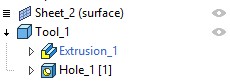
As the model tree branch with the Body history expands, the glyph changes to ![]() . The Body history consists of a sequence of their defining operations, displayed as a list. The list is formed from top down in the order of creating or using operations. To hide the Body history, point to the glyph
. The Body history consists of a sequence of their defining operations, displayed as a list. The list is formed from top down in the order of creating or using operations. To hide the Body history, point to the glyph ![]() and click
and click ![]() .
.
Each model element entered in the Body history has a unique name. By default, the name consists of the name of the element type and a number, for example, “Extrusion_6”. If desired, the element, just like a Body, can be assigned an arbitrary individual name.
Named geometrical elements (edges, faces, etc.) can then be used to perform measurement, search of parent element used in operations. Searches can be performed via the Edit > Find command or Find section of Edit system toolbar. Named elements are available for obtaining information about the dependencies in "Information" command dialog. Option Delete that removes dependent objects is also available for them. Named elements, when used for subsequent creation of new operations based on them, retain their names. If the named geometric element is located on a visible body, it is marked in the 3D window when it is selected in the model tree.
|
You can change the geometric element name using the Parameters command in its context menu. Names may be set for vertexes, edges, cycles, faces.
|
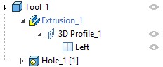
The ![]() glyph before the element means this element is based on other elements. To expand this model tree branch and view the element’s parents, point the mouse to the glyph
glyph before the element means this element is based on other elements. To expand this model tree branch and view the element’s parents, point the mouse to the glyph ![]() and click
and click ![]() . After that, the glyph will change to
. After that, the glyph will change to ![]() . If there is no glyph before the element, this means the element is the last one on this branch of the 3D model tree.
. If there is no glyph before the element, this means the element is the last one on this branch of the 3D model tree.
If the creation history can be built for an operation, then the history will be displayed instead of the parents. In this way, the ![]() glyph is put before the operation name instead of the
glyph is put before the operation name instead of the ![]() glyph. An operation's history is displayed in the same way as a Body’s history.
glyph. An operation's history is displayed in the same way as a Body’s history.
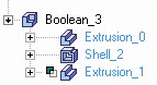
The Boolean operations are displayed in a special way in the history. The type of Boolean (addition, subtraction or intersection) is drawn before the icon of the operation that comes as the second operand of the Boolean. The diagram shows the history of the operation “Boolean_2”: the body “Extrusion_1” is subtracted from the body “Extrusion_0”.
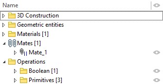
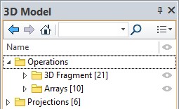
In addition to the list of Bodies, in the root of the model tree there are also special branches of the tree in which all 3D elements created in the current model are enumerated. Auxiliary 3D elements are put on the branch "3D Construction". All operations are on the second branch, "Operations". 3D annotation (3D dimensions, 3D leader notes, etc.) are put into the branch “3D service elements”. The "Constraints" branch lists all constraints created in the given model. All elements are sorted into the folders by types: 3D Nodes, Workplanes, 3D Profiles, etc.; within the folders, the elements are sorted alphabetically. The number next to the folder name and the colon means the number of elements of this type contained in the model. By expanding branches of the model tree, you can access any element of the 3D model.
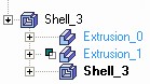
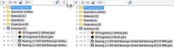
In certain cases, operations can be reordered by moving their labels within the model tree. This effectively changes the model structure and geometry. Press ![]() on the element label and drag it to a new location in the tree. The following diagrams demonstrate the result of reordering an element in the model tree. In the beginning, the operation Shell_3 followed the subtraction operation Boolean_2. Then, the Boolean, together with its tool body operand Extrusion_1 (a cylinder), was reordered to be after the shell operation.
on the element label and drag it to a new location in the tree. The following diagrams demonstrate the result of reordering an element in the model tree. In the beginning, the operation Shell_3 followed the subtraction operation Boolean_2. Then, the Boolean, together with its tool body operand Extrusion_1 (a cylinder), was reordered to be after the shell operation.


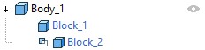
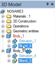
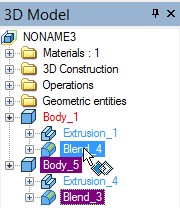
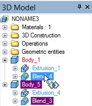
The model tree helps quickly create Boolean operations of all types. If you select a Body and drag it over another Body, the indicator of the Boolean “addition” will appear at next to the pointer. If you additionally press the key <Ctrl> or <Shift>, the type of the Boolean changes to subtraction or intersection, respectively. Instead of Bodies, you can select operations that are last in their histories.
3D Model tree in 3D scene
The 3D Model window can be also displayed in the 3D scene. For this purpose press ![]() icon in the top left corner of the 3D scene.
icon in the top left corner of the 3D scene.
If the 3D Model window becomes at some point not available when working with a 3D model, the model tree is automatically expanded in the scene. This occurs, for example, when entering commands of 3D elements creating or editing. If the expansion of the tree upon commands activation is not required, it is enough to close it once using ![]() and the system will remember this status.
and the system will remember this status.
The model tree has a toolbar that is similar to the toolbar in the 3D Model window. The only difference is the number of columns to be displayed. To hide this toolbar you need to click on a special button.
![]()
The tree can be expanded. To do this place the cursor on the right edge of the toolbar and move it holding the left mouse button.
Model Tree Context Menu
By pointing to an element in the model tree, you can access the context menu (by pressing ![]() ).
).
The context menu consists of standard commands for working with element (Edit, Copy/Paste, Parameters and so on) and with 3D Model window.
The context menus may vary depending on the element selected in the 3D Model window.
Besides the common commands for managing the selected element, the context menu contains some additional commands for working with particular Bodies, operations and the model tree as a whole:
Delete Body (for Bodies). This command serves to delete all the operations which are part of this Body's creation history. In addition, all parent 3D construction elements of this Body can be deleted, or just those parent elements that are not referenced by other created Bodies.
Delete (for operations and auxiliary 3D elements). The command deletes the selected operation or 3D construction element.
Detail command allows to unload a body or a fragment from the assembly into a separate file.
More information about detailing can be found in “Assemblies creation” chapter.
Remove mate transformations. Option allows to remove all mate transformations of the selected object and to return it to the initial state.
Rollback model option allows to rollback a three-dimensional model to the level of the specified operation.
More information about rollback model can be found in “Edit” chapter.
Retain geometry after recalculation option allows you to save intermediate geometry for the operation, thereby accelerating transition to its editing.
More information about the option can be found in “Edit” chapter.
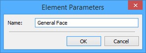
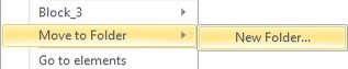
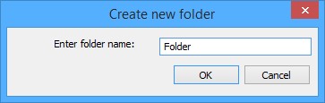
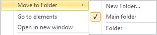
Separate branches-folders can be created for grouping Bodies, 3D fragments and 3D array. To do it, in the context menu for the Body which you want to put into a separate folder, invoke the command Move to Folder > New folder from the context menu. A window for specifying the name of the folder being created will appear on the screen. After specifying the name and pressing [OK], there will be a folder having the specified name in the tree of the 3D model, and the selected Body will be put into this folder.
If in the tree of the 3D model at least one Body folder has been already created, in the context menu for each body in the submenu Move to Folder, a list of existing Body folders will be also present. The folder that contains the current body will be marked. For moving Body into one of the already existing folders, it is enough to select the folder in the list.
It is also possible to move Bodies from the root of the model tree to the folder and backwards just by dragging Bodies while pressing ![]() .
.
Selecting objects with the help of the model tree is sometimes very convenient in many commands, for example, when selecting this element in the 3D window is difficult for some reasons.
The Visibility group of commands unites the commands to control the visibility of Bodies and 3D construction elements:
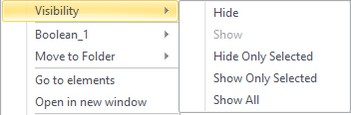
Hide. This command makes the selected 3D objects invisible in the 3D scene;
Show. This command cancels the previous command, making the selected 3D objects visible in the 3D scene;
Hide Only Selected. This command makes all selected 3D objects invisible, and shows all the rest, if those were previously hidden.
Show Only Selected. This command makes all the selected 3D objects visible, and hides (makes invisible) the rest;
Show All. This command makes all objects in the 3D scene visible.
The accessibility of the commands in the group depends on which 3D objects are selected. For example, if all selected 3D objects are currently hidden, then the “Hide” command will be inaccessible.
The hidden/shown Body state can be defined using the “Hide” option in the Body's parameters dialog without the use of the described commands. This option's value can be defined via a variable. If a variable is used, then the commands of the “Visibility” group will not affect the visibility of such Body. This will be stated in the provided warning message.
Suppress (for operations). This command excludes the operation from regeneration. This allows user to temporarily remove 3D model elements. To select a suppressed operation, use the "3D Model" window or do the element search.
Only selected elements will be displayed in the tree upon using Go to elements command. Status switching options ![]() ,
, ![]() ,
, ![]() are used to return to the normal mode.
are used to return to the normal mode.
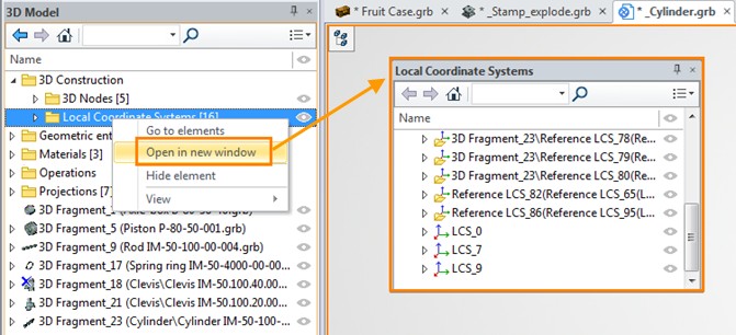
You can create a separate window for the selected elements using Open in new window command. This window can be moved around the screen. It retains all the functionality of the 3D Model window. This window eliminates having to move the cursor across the screen to select an element in the model tree.
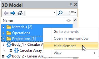
After using Hide element command, the selected elements will not be displayed in the model tree. For example, you can hide unused items, so as not to be distracted by them.
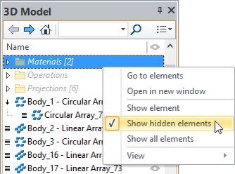
If the flag Show hidden elements is active, all hidden elements are displayed but greyed. The elements names are shown in italic to distinguish them from the suppressed elements.
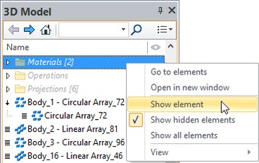
To display elements again you may use Show element command.
View item includes commands and options to customize the display of model tree such as Display parameters, Use active View filter, Appearance.
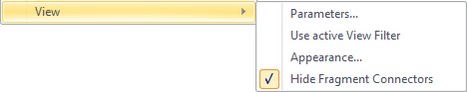
In the View parameters window you can set colors for: 3D Model window, selected elements, invisible elements, marked elements and hidden elements. In each of these groups, you can set text color and background color.
View group
The View group in the Parameters dialog is different for the 3D model window and the model tree in the 3D scene.
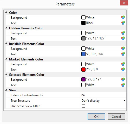
Use active View Filter. The 3D window selector can be adjusted for selecting elements in the model tree. To activate the filter, flag this item in the context menu. When you move the cursor over the items in the tree, only the elements corresponding to the active filter will be highlighted.
Indent of sub-elements parameter allows to specify the indentation of child elements in the model tree relative to the parent element in pixels.
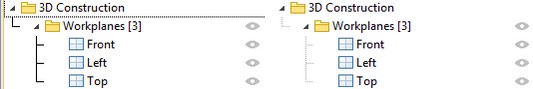
Tree Structure parameter allows to set visual representation of the tree structure. The following options are available: don’t display, lines, dots.
Blur background borders and Rounding of background box corners parameters are available for 3D Model window in the 3D scene.
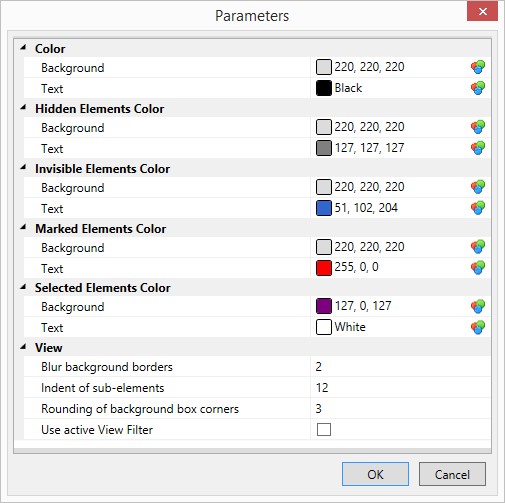
Use active View Filter - duplicate the appropriate flag from View parameters.
Appearance… This command allows a user to customize information which is displayed in the tree of the 3D model. Upon calling this command, the settings dialog window appears.
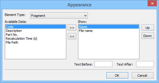
In the dialog “Appearance”, it is possible to select items which will be displayed in the tree for objects of various types: time spent by a computer on object recalculation, the memory size of the geometric data for the object and the size of the data required for its displaying (mesh), etc. This customization allows a user not only to see the objects in the tree in the convenient for the user form, but also carry out the recalculation time and the memory usage optimization for the model. The information about the name and description of the assembly components can be also convenient when working with the assembly models. This information can be displayed together or instead of the filename and the path of the file for the assembly components (fragments).
Settings specified in the dialog “Appearance” are saved in the document file and used upon its subsequent opening.
Hide fragment connectors. When the flag is active, fragments connectors are not displayed in the 3D scene.