Opening New Windows |
  
|
Opening New Windows |
|
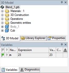
When creating a new document from a 3D model prototype, a 3D window opens first. Later in design, the user may need to open additional 2D or 3D windows.
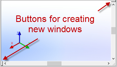
Use the special buttons on scroll bars for this purpose. This buttons activates «Views Placement” dialog box, where you can select the location of new views.
In “Views Placement” window you can select one or several 2D and 3D views using special buttons.
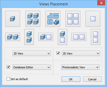
For custom views placement you can use the drop down lists in the lower part of the dialog box. Mark the required views with ![]() . The following types of the new views are available: 3D view, 2D view, Database Editor and Photorealistic View. They can be assigned in any order and in any combination.
. The following types of the new views are available: 3D view, 2D view, Database Editor and Photorealistic View. They can be assigned in any order and in any combination.
Use “Set as default” option to create predefined set of views when creating new windows in “Window/New Window” command.
If the original file was created from a drawing prototype, the 2D window was opened first. A simple way to create another 3D window is to click on the button with a triangular arrow in the right-top corner of the graphic area of the current window.
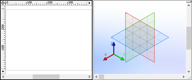
As a result, the graphic area of the current window will split in two equal parts, a 2D window on the left, and a 3D one on the right.
Finally, one can call the command for opening a new window, "WO:Open New Window" by typing on the keyboard or via the textual menu "Window|New Window".
Depending on what kind of window is currently active, some or other commands will not be accessible. Thus, if a 2D window is active then the 3D Visualization commands won't be accessible, and neither will be 3D view controls. Vise versa, while in a 3D window, the most of 2D commands could only be accessed in a special mode - when a workplane is activated.
You can fix the particular set of views for the document window for usage in subsequent sessions by activating “Fixed set of windows” option in the “3D” tab of “ST: Set Document Parameters” command. The document should be saved to apply changes.
Manipulating model in 3D window
While working in 3D window a model can be spun in any way, zoomed at in and out, and panned. These actions can be done at any moment using mouse or keyboard input. When using the mouse, sometimes it is necessary to set certain options on the "View" toolbar (located at the right side of the screen).
To spin the 3D scene while working on an active workplane, use the button ![]() found on the main toolbar in the mode “Workplane” or “Workplane (Sketch)”. It is also possible to spin the model with the help of the mouse simultaneously pressing the <Alt> key.
found on the main toolbar in the mode “Workplane” or “Workplane (Sketch)”. It is also possible to spin the model with the help of the mouse simultaneously pressing the <Alt> key.
For more details see the chapter "Working with the 3D view window".
Arranging tool windows economically
All tool windows in the T-FLEX CAD application can be combined in a common console with tabs. This saves up the working area on screen and eases the user from constantly adjusting the windows borders while working with the application. To combine two windows, pick one of them with ![]() at the title area and drag into the title area of the other window. The two windows collapse into the common console. To switch between the windows, use the tabs that appear in the bottom of the console. The system may automatically switch between the windows during operation.
at the title area and drag into the title area of the other window. The two windows collapse into the common console. To switch between the windows, use the tabs that appear in the bottom of the console. The system may automatically switch between the windows during operation.
Arranging Tool Windows
All tool windows in the T-FLEX CAD application can be combined in a common console with tabs. This saves up the working area on screen and eases the user from constantly adjusting the windows borders while working with the application. To combine two windows, pick one of them with |
|
Toolbars
Toolbars provide additional convenience to T-FLEX CAD 3D operation. Working with toolbars, their customization and access to toolbars are done in the same way as in the 2D drawing mode. Further refer to the chapter "Basics of System Management".
The necessary options of the command are set using the automenu together with the property window, similar to the 2D mode. The set of icons in the automenu is specific to each command. However, some options in the automenu are common for all commands.
![]() <Y> Finish input. Confirms element creation
<Y> Finish input. Confirms element creation
![]() <P> Set entity parameters
<P> Set entity parameters
![]() <I> Select other element
<I> Select other element
![]() <Esc> Cancel selection
<Esc> Cancel selection
![]() <F4> Execute Edit command
<F4> Execute Edit command
![]() <X> Exit command
<X> Exit command
![]() <F5> Preview Operation Result
<F5> Preview Operation Result
Customization
Certain customization is necessary for working with T-FLEX CAD. Customization settings include both the system-wide ones, and those specific to a particular document. The system settings are automatically saved in the Windows registry and are applied at subsequent starts of T-FLEX CAD. The settings specific to a particular document are saved with the document. The system customization is done via the "Options" dialog box, invoked by the command
Icon |
Ribbon |
|---|---|
|
|
Keyboard |
Textual Menu |
<SO> |
Customize > Options |
All system settings related to 3D modeling are located on the "3D" tab. For more details on working with "Options" dialog refer to the chapter "Customizing System".
Customization of document parameters is done via the "ST: Set Document Parameters" dialog box invoked by the command
Icon |
Ribbon |
|---|---|
|
Edit → Document → Document Parameters
|
Keyboard |
Textual Menu |
<ST> |
Customize > Document Parameters |
All drawing settings related to 3D modeling are located on the "3D" tab. For more details see chapter "ST: Set Document Parameters".