Moving and Copying Drawing Elements. Arrays. Use of Clipboard |
  
|
Moving and Copying Drawing Elements. Arrays. Use of Clipboard |
|
T-FLEX CAD provides two main mechanisms for creating new 2D elements based on existing ones.
The first mechanism relies on moving, copying and array creation commands. This group of commands unites all functions related to translating, scaling, using symmetry and rotating arbitrary 2D elements, as well as creating various types of associative and independent copies, including linear and circular arrays. Moving/copying of elements can be done within the current page of a T-FLEX CAD document or from one page to another one.
The second mechanism uses copying via the clipboard that is a somewhat extended functionality in T-FLEX CAD as compared with the standard Windows clipboard management. This mechanism only supports non-associative (independent) copies. However, it supports copying between different documents within the same T-FLEX CAD environment, as well as exchange with other applications.
Any T-FLEX CAD 2D elements can be handled by either of the moving/copying mechanisms, except those specifically mentioned in the respective sections (for example, multi-page text and BOMs cannot be copied or moved).
Moving, copying and array creation commands
A family of commands is provided in T-FLEX CAD for moving, copying and array creation. These commands are used for transforming existing drawing elements and making various types of copies, including multiple (arrays). All commands have similar interface and underlying mechanism that allow easy switching from one command to another while keeping the same set of selected objects. These commands also interact with object snapping described in the chapter "Sketch". Upon calling any of the commands, the toolbar is displayed for object snapping management.
The commands are divided into three large groups by their purposes:
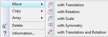
● The commands for moving (for modifying the existing elements – translation "TM: Move", rotation "TT: Move and Rotate", scaling "TA: Move and Scale", symmetry "TS: Move with symmetry"); translation with rotation “TP: Move with translation and rotation”)
● The commands for creating copies (copying with translation "XM: Create Copy", copying with rotation "XT: Copy and Rotate", with scaling "XA: Copy and Scale", creating copies symmetrical to the original elements "XS: Create Symmetry") and copying with translation and rotation “XE: Copy with translation and rotation”);
● Array creation commands (linear "XL: Create Linear Array" and circular "XR: Create Circular Array").
Since the interface of all the commands is identical, the further description will be as general as possible, covering all moving, copying and array creation commands.
Calling the commands
The commands for moving elements are available under the textual menu entry "Edit":
Keyboard |
Textual Menu |
Icon |
<TM> |
«Edit|Move|with translation» |
|
<TT> |
«Edit|Move|with rotation» |
|
<TA> |
«Edit|Move|with scaling» |
|
<TS> |
«Edit|Move|with symmetry» |
|
<TP> |
Edit|Move|with translation and rotation» |
|
The copying and array creation commands are grouped under the menu entry "Draw":
Keyboard |
Textual Menu |
Icon |
<XM> |
"Draw|Copy|with translation" |
|
<XT> |
"Draw|Copy|with rotation" |
|
<XA> |
"Draw|Copy| with scaling" |
|
<XS> |
"Draw|Copy|with symmetry" |
|
<XE> |
«Draw|Copy|with translation and rotation» |
|
Keyboard |
Textual Menu |
Icon |
<XL> |
"Draw|Array|Linear Array" |
|
<XR> |
"Draw|Array|Circular Array" |
|
Upon calling any moving, copying or array creation command, the first step will always be selecting the objects for moving or copying. The following options will be provided in the automenu:
![]() <End> Finish element selection
<End> Finish element selection
![]() <M> Add elements to be copied
<M> Add elements to be copied
![]() <M> Remove elements to be copied
<M> Remove elements to be copied
![]() <I> Select Other Element
<I> Select Other Element
![]() <Esc> Exit command
<Esc> Exit command
Any T-FLEX CAD 2D elements are available for selection. Elements can be selected by box and/or using ![]() under the active option
under the active option ![]() . Selection can be canceled in the same way with the active option
. Selection can be canceled in the same way with the active option ![]() . To speed up the process, you can use the transparent mode of switching between adding and removing elements: pressing the <Ctrl> inverts the current mode. This means, if the current active option was
. To speed up the process, you can use the transparent mode of switching between adding and removing elements: pressing the <Ctrl> inverts the current mode. This means, if the current active option was ![]() , pressing <Ctrl>+
, pressing <Ctrl>+![]() will be removing the elements from the selected set, and vice versa, with the active option
will be removing the elements from the selected set, and vice versa, with the active option ![]() pressing <Ctrl>+
pressing <Ctrl>+![]() will result in adding the picked elements to the set. To complete the selection, use the option
will result in adding the picked elements to the set. To complete the selection, use the option ![]() .
.
After selecting the objects for moving/copying, the system will switch to the main automenu of the specific command.
The commands can also be called from the context menu when selecting one or several 2D drawing elements. In any case, the main automenu of the selected command will appear at once in this case. All the objects that were selected at the time of calling the context menu will be subject to the transformation.
The common options of the moving, copying and array creation commands
For working convenience, all moving, copying and array creation commands have similar sets of automenu options.
Such options include the options for switching between the commands, the attachment point selection options and the options that define the action upon the completion of the current transformation.
Options for switching commands
The automenus of all moving, copying and array creation commands include the options, whose composition defines the current command. These options are used for quick switching between the commands while keeping the selected set of objects.
The moving, copying and array creation commands differ primarily in the type of the transformation and its mode. The transformation mode is either moving (modification of the selected elements) or copying (creation of new elements based on the selected). The type of transformation defines the kind of change between the original position and the target position. This can be a translation, rotation, scaling, translation with rotation, creation of a linear or circular array. Thus, for example, the combination of the "Move" mode and "Translate" transformation makes the command "TM: Move", while the "Copy" mode in combination with the same transformation makes the command "XM: Create Copy with translation". Note that the array creating transformations always make copies.
The kind of transformation is defined by the first automenu option ![]() that contains the enclosed list:
that contains the enclosed list:
![]() <Ctrl+M> with Translation
<Ctrl+M> with Translation
![]() <Ctrl+T> with Rotation
<Ctrl+T> with Rotation
![]() <Ctrl+Q> with Scale
<Ctrl+Q> with Scale
![]() <Ctrl+U> with Symmetry
<Ctrl+U> with Symmetry
![]() <Ctrl+L> Linear Array
<Ctrl+L> Linear Array
![]() <Ctrl+K> Circular Array
<Ctrl+K> Circular Array
The default automenu option corresponds to the current command.
The current transformation mode is defined by the following options:
![]() <C> Move
<C> Move
![]() <R> Copy
<R> Copy
You can turn on only one option at the time: pressing one option automatically undoes the other one as in a radio group. The current mode is defined by the active option. Setting the option ![]() switches to one of the commands in the "Move" group, while setting the option
switches to one of the commands in the "Move" group, while setting the option ![]() - activates a command in the group "Copy" or "Array".
- activates a command in the group "Copy" or "Array".
If the "Linear Array" or "Circular Array" transformation is active, the options for selecting a transformation mode are not shown in the automenu.
Defining base points of transformation
When defining a transformation, you need to specify two special points - origin and target. These points define the transformation direction and parameter. Depending on the kind of transformation, either both or just one point is required.
Origin point is the point that marks the original position of the objects to be transformed. This would be the start point of a translation, the center of a rotation, the center of scaling or the start point of a linear array.
The origin point of a transformation can either be defined as an arbitrary point, or be selected as one of the characteristic points of the outlining rectangle. The outlining rectangle is a rectangular area that covers the extents of the set of objects selected for the transformation. Characteristic points of the outlining rectangle are its center, corners and the side midpoints.
The way of defining the origin point of a transformation is selected from the following pull-down list under the option ![]() :
:
|
<Ctrl+0> |
Left Top |
|
<Ctrl+1> |
Center Top |
|
<Ctrl+2> |
Right Top |
|
<Ctrl+3> |
Left Center |
|
<Ctrl+4> |
Center |
|
<Ctrl+5> |
Right Center |
|
<Ctrl+6> |
Left Bottom |
|
<Ctrl+7> |
Center Bottom |
|
<Ctrl+8> |
Right Bottom |
|
<Ctrl+9> |
Free attachment mode (arbitrary point selection) |
The default setting is the free attachment mode ![]() . In this case, the origin point is defined by specifying the coordinates in the property window or by clicking
. In this case, the origin point is defined by specifying the coordinates in the property window or by clicking ![]() in the 2D window, or else by selecting an existing 2D node. To select a node, you can use the option:
in the 2D window, or else by selecting an existing 2D node. To select a node, you can use the option:
![]() <N> Select Node
<N> Select Node
If the free attachment mode was selected, defining the origin point will be the first step of moving/copying.
Target point is the point defining the target position of the objects after the transformation. This can be the end point of a translation, the end point of a linear array (defining its length and step), or the center of the circular array. The target point of the transformation is always defined by specifying its position by mouse clicking ![]() , in the property window, or by selecting a 2D node (the option
, in the property window, or by selecting a 2D node (the option ![]() ).
).
Option for selecting action after the current transformation
You can select a desired action upon completing the transformation from the enclosed list of the option ![]() :
:
|
<Alt+X> |
Exit Command automatically when finished |
|
<Alt+O> |
Repeat Command for selected elements |
|
<Alt+N> |
Repeat Command for created elements (available for copying only) |
|
<Alt+A> |
Repeat Command for selected and created elements (available for copying only) |
|
<Alt+S> |
Select new elements when finished |
The selected option defines the system action upon completing the original transformation:
![]() - the system automatically exits the move/copy command.
- the system automatically exits the move/copy command.
![]() ,
, ![]() ,
, ![]() - upon the completion of the first transformation, the command instantly activates the mode of defining a new transformation. This will be indicated by a new set of objects for transformation, rubberbanding with the pointer, and the respective prompts displayed in the status bar (such as, "Set destination point for Move"). Depending on the selected option, the new set of objects for moving/copying will include either the original objects of the first transformation, or the objects created as a result of the first transformation, or else all of the above.
- upon the completion of the first transformation, the command instantly activates the mode of defining a new transformation. This will be indicated by a new set of objects for transformation, rubberbanding with the pointer, and the respective prompts displayed in the status bar (such as, "Set destination point for Move"). Depending on the selected option, the new set of objects for moving/copying will include either the original objects of the first transformation, or the objects created as a result of the first transformation, or else all of the above.
![]() - upon the completion of the first transformation, the command switches to the mode of selecting objects (see the section "Calling the command from menu").
- upon the completion of the first transformation, the command switches to the mode of selecting objects (see the section "Calling the command from menu").
Common options of moving commands
This section covers all the commands that allow creating copies of the selected objects. Those are the commands for copying with translation XM: Create Copy, copying with rotation XT: Copy and Rotate, copying with scaling XA: Copy and Scale and creating symmetrical objects XS: Create Symmetry, and copying with translation and rotation XE: Copy with translation and rotation as well as the array creation commands XL: Create Linear Array and XR: Create Circular Array.
Options for selecting moving mode
When executing any moving command (translation, rotation, scaling or symmetry), you can set various modes of executing these transformations. The mode selection is done in all cases by one of the automenu options in the list:
![]() <O> Change dependent elements
<O> Change dependent elements
![]() <G> Change related elements
<G> Change related elements
![]() <F> Change selected elements
<F> Change selected elements
Change dependent elements. The selected elements are moved together with their parents and immediate dependents only.

Change related elements. The selected elements are moved together with all objects related via parents or dependents.

Change selected elements. Only the selected elements are moved, separated from parents and dependents.
In complex cases, when it is impossible to break a relation between the element and its parents and/or dependents, the following exceptions from this rule are possible:
● If the selected object can't be separated from a parent, a copy of the parent is created, that moves together with the selected object. The original parent element is left unchanged;
● If the selected object cannot be separated from a dependent, then the object is moved, while its copy is created in the original position to which the dependent is attached;
● If the selected objects have a common parent construction entity that cannot be moved (such as a node or a construction line), and the parent does not have any other dependents that cannot be moved, then the parent is moved along.
Dynamic model regeneration mode
When defining various types of moving in the modes "Change dependent elements" and "Change related elements", you can turn on the dynamic model regeneration mode to view the modifications of the elements related or attached to the selected ones (the selected elements themselves are always updated dynamically). To turn on this mode, use the option ![]() .
.
Options for handling variables
If the original position of the selected elements (or the elements used for defining the selected ones) was driven by variables, use the options ![]() and
and ![]() when moving the elements. These options cannot be used together. When one is engaged, the other becomes inaccessible.
when moving the elements. These options cannot be used together. When one is engaged, the other becomes inaccessible.
If none of these options is active, then after selecting the new position for the elements being transformed, a message is displayed on the screen, prompting the user for modifying the value of the respective variable. Pressing the [Ok] button completes the transformation with updating the variable. Pressing [Cancel] aborts the transformation. In the case when several variables are affected, the prompts will be displayed subsequently for each of the variables. Checking the item "For all variables" in one of the prompt windows confirms adjustment of all the rest of the variables without querying.
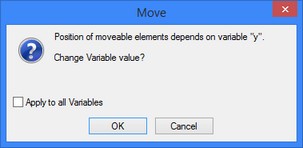
With the option ![]() turned on, the values of the respective variables are adjusted without querying.
turned on, the values of the respective variables are adjusted without querying.
The option ![]() replaces all the variables used for defining the coordinates of the transformed elements by their respective values. The variables themselves are not deleted from the model. The variables related to other element parameters are not affected by moving.
replaces all the variables used for defining the coordinates of the transformed elements by their respective values. The variables themselves are not deleted from the model. The variables related to other element parameters are not affected by moving.
Common options of copying and array creation commands
This section covers all the commands that allow creating copies of the selected objects. Those are the commands for copying with translation "XM: Create Copy", copying with rotation "XT: Copy and Rotate", copying with scaling "XA: Copy and Scale" and creating symmetrical objects "XS: Create Symmetry" and copying with translation and rotation “XE: Copy with translation and rotation” as well as the array creation commands "XL: Create Linear Array" and "XR: Create Circular Array".
Options for selecting copying modes
When executing any copying command, one can use various copying modes. The mode selection is done in all cases by one or the automenu options in the list:
![]() <F> Create Associative Copy
<F> Create Associative Copy
![]() <J> Create Copy on Associated Constructions
<J> Create Copy on Associated Constructions
![]() <G> Explode Copy keeping relations
<G> Explode Copy keeping relations
![]() <O> Explode Copy
<O> Explode Copy
Create Associative Copy. This option creates an associative copy, whose elements maintain the relation with the original parent elements. The copied elements will automatically adjust, as the original elements are modified.
Create Copy on Associated Constructions. For selected construction elements the associated copies are created. Copies of the drawing elements are detached from the original parent elements and snapped to the copies of the construction elements. If this mode is used while creating rectangular or circular arrays, the drawing elements will be created only at the moment of array creation. Increasing the number of elements in the array does not lead to appearance of new graphics lines and other drawing elements.
Explode Copy keeping relations. The created copy operation is automatically destroyed. The elements created by this operation become independent from the original parent elements. However, the internal relations are maintained between the resulting objects similar to those that existed between the original elements. The relations with variables are maintained if the variable values are not affected. Otherwise, the variables are replaced by constants.
If a copied object has a parent that was not among the set of the objects to be copied, then upon destroying the copy operation, a copy of the parent element will be created that will move together with the selected object. To prohibit this, turn on the additional option:
![]() <Alt><T> Copy only selected elements
<Alt><T> Copy only selected elements
With this option turned on, the system tries to separate the objects being copied from their parents that were not included in the set of the objects to copy (similar to the mode "Change selected elements" in the moving commands).
Explode Copy. The created copy is automatically broken up into the separate unattached objects. The copied construction elements become stand-alone objects, regardless of the ways of their parent element creation. All variables that were driving the parameters of the original elements are replaced by constants in the new elements.
For successful copying of the detailing elements (dimensions, leader notes, roughness symbols, tolerances, etc.) in the modes "Create Associative Copy" and "Explode Copy", make sure that the set of the objects to be copied includes the elements and their parents as well. Otherwise, the copy will not be created. To avoid this, let the system automatically append the selection with the required parent elements by including those in the set of objects to be copied. This mode is turned on by the additional automenu option:
![]() <K> Autoselection of required parents
<K> Autoselection of required parents
Attachment node creation option
When creating associative copies and arrays, selecting an existing 2D node (the option ![]() ) as a base point of the transformation automatically establishes a relation between this base point and the selected node. As a result, the position of the base point will change according to modifications to the node position, causing repositioning of the whole copy. If the necessary nodes do not exist, those can be created automatically using the option:
) as a base point of the transformation automatically establishes a relation between this base point and the selected node. As a result, the position of the base point will change according to modifications to the node position, causing repositioning of the whole copy. If the necessary nodes do not exist, those can be created automatically using the option:
![]() <T> Create Node at point
<T> Create Node at point
When the option is turned on, a 2D node is created automatically at the point of the mouse click when defining the base points of the transformation. The base points become attached to this node.
Translation
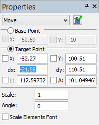
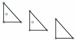
To define translation or copying with translation, specify the start point (the origin point of the transformation) and the end point (the target point of the transformation). If using the mode of automatic origin point location based on characteristic points of the outlining rectangle, you shouldn't define the start point. The transformation is performed by carrying the start point over the end point.
Additionally, you can change the scale and the rotation angle of the translated image in the property window. Option “Scale elements font” controls scaling of the drawing elements added to the copy set. When the flag is on font size of all elements being copied will be scaled according to the assigned scale factor. When the flag is off, font size remains unchanged. The flag does not affect font size of the text being copied – it is always scaled. When defining the end point of the transformation, you can restrict pointer movements by snapping to the coordinate axes. This helps defining a vertical or horizontal transformation. The related options are |
|
 or
or 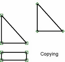
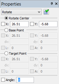
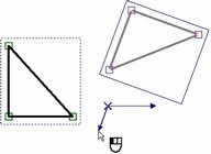
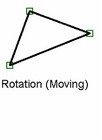
Rotation
When defining a rotation, three points are specified in a general case: the center of rotation (the attachment point), the start point and the end point. Rotation is done about the specified center. The rotation angle is defined as the angle between the vectors constructed from the rotation center to the start and end points. The value of the rotation angle can be specified numerically or by a variable in the property window. When using the mode of the origin point automatic definition based on characteristic points of the outlining rectangle, the rotation center is defined automatically. |
|
 or
or 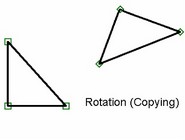
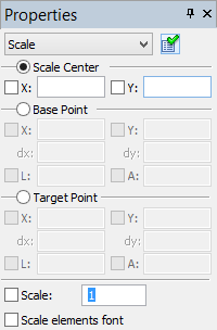
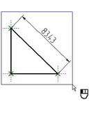
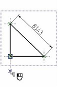
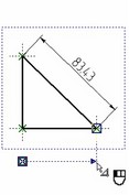
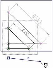
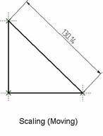
Scaling
When scaling and image, you need to specify the three points, just as in the case of rotation: the center of scaling, the start point of scaling and the end point of scaling. The center of scaling is determined automatically in the case of using the mode of automatic definition of the origin point based on the characteristic points of the outlining rectangle. The scaling factor is computed as the ratio of the distances between the center and the end point and between the center and the start point. The scaling factor can also be defined numerically or by a variable in the property window. “Scale elements font” flag controls scaling of the drawing elements (analogous to the flag with the same name for Translation). |
|
 or
or 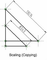
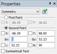
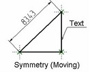
Symmetry
To define symmetry, specify just the symmetry axis to mirror the selected object about. The axis can be defined by either selecting an existing straight line or segment using the option ![]() , or by defining two points for the symmetry axis to pass through. Existing 2D nodes can be used as the points.
, or by defining two points for the symmetry axis to pass through. Existing 2D nodes can be used as the points.
 or
or 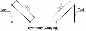
The options |
|
When mirroring text, you can check the additional flag "Symmetrical Text" in the property window. When the flag is cleared, only the text position is affected by the symmetry. When set, the text contents are also mirrored symmetrically.
Moving with Rotation
For creation of translations with rotation or of analogous copying it is required to specify: ●initial point (this is an initial point of transformation and the first point of the initial direction vector); ●initial direction vector (the end point of a vector is specified); ●end point (this is a target point of transformation and the first point of the final direction vector); ●final direction vector (the end point of a vector is specified). If the mode of automatic determination of the initial point on the basis of one of the characteristic point of the encompassing rectangle is enabled, the initial point is not specified.
|
|
Transformation is carried out by translating the initial point to the end point (target) and rotating with respect to the end point at an angle between the initial and final direction vectors. In the properties window you can specify the magnitude of angle of additional rotation (it is added to the angle specified by the vectors).
In addition, in the properties window it is possible to change the scale of the image being translated. The “Scale font size of formatting elements” flag allows us to control the scaling of the formatting elements that are included into the set of copied objects.

 or
or 
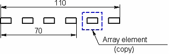
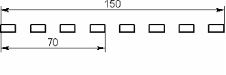
Linear Array
To create a linear array, you need to specify two points: the start (origin) and the end (target). 2D nodes can be used as points: the existing ones (the option ![]() ) or the ones automatically created using the option
) or the ones automatically created using the option ![]() . When creating an associative array (the option
. When creating an associative array (the option ![]() ), it will be attached to the nodes automatically. The specified points define the direction vector of the array and its step, length or the number of copies, depending on the way of defining the array. The copies will be positioned along the array direction vector.
), it will be attached to the nodes automatically. The specified points define the direction vector of the array and its step, length or the number of copies, depending on the way of defining the array. The copies will be positioned along the array direction vector.
After defining the first point, the array elements start rubberbanding on the screen. Their number depends on the default setting of the number of copies in the property window. To complete the array creation, simply select the position of the end point.
The start point of the array is determined automatically in the case of using the mode of automatic definition of the origin point based on the characteristic points of the outlining rectangle.
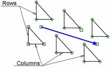
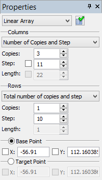
The array can be two-dimensional, that is, composed of several rows. The rows are created in the direction orthogonal to the direction vector. The number of copies in the direction orthogonal to the specified vector (that is, the number of rows), and their parameters (the step or the total length) can be defined among the array parameters in the property window. The group "Columns" defines the parameters of the columns in the linear arrays (the copies positioned along with the direction vector): |
|
Mode. Sets the definition mode of the linear array: "Number of Copies and Step", "Length and Step", "Number of Copies and Length". Depending on the selected definition mode, the distance between the points specified at the array creation can be defining, respectively: the step (the number of copies is always defined by a numerical value); the step or the length, at user's choice; the total length of the array (the number of copies is again defined by a numerical value). The values of the step and the total length of the array can be defined by numerical values in the property window as well (the parameters "Step" and "Length"). To do this, check the flag next to the desired parameter. The specified points will in this case define the array direction only. The number of copies is always defined by a numerical value using the parameter "Copies". The original elements are included in the count of copies. The accessibility of parameters "Copies", "Step" and "Length" is determined by the selected mode of defining the array. |
|
The group of parameters "Rows" defines the respective parameters of the rows of a linear array.
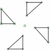
Circular Array
To create a circular array, after selecting the objects to copy you need to specify the center point of the array. You can specify a 2D node as the center using the option ![]() . The option
. The option ![]() allows creating a node in the specified point with automatic attachment to that node (for the associative array). After selecting the objects to copy and before specifying the center of the array, the array elements rubberband on the screen. The number of elements and the angle swept by the elements are defined by the default values. The array parameters can be modified in the property window. Here you can define:
allows creating a node in the specified point with automatic attachment to that node (for the associative array). After selecting the objects to copy and before specifying the center of the array, the array elements rubberband on the screen. The number of elements and the angle swept by the elements are defined by the default values. The array parameters can be modified in the property window. Here you can define:
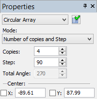
Mode. Sets the definition mode for the circular array: "Number of copies and total angle", "Total angle and Step" or "Number of copies and Step". Depending on the selected mode, some parameters may be inaccessible (computed automatically): Copies. Defines the total number of copies in the array, including the count of the original elements. Step. Defines the angle between the copies of the array. Total Angle. This parameter allows defining the total angle that will be swept by the array elements. |
|
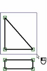
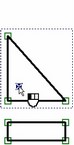
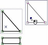
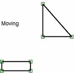
Calling the commands in transparent mode
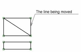
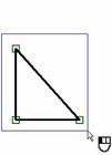
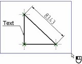
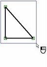
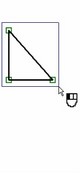
The command "TM: Move" can be called in "transparent mode" when one or several T-FLEX CAD 2D elements are selected. The elements can be selected by box and/or using <Shift>+![]() , <Ctrl>+
, <Ctrl>+![]() . After selecting the elements, simply point the mouse at one of the highlighted nodes or the border lines of the object being moved. The pointer then assumes the shape
. After selecting the elements, simply point the mouse at one of the highlighted nodes or the border lines of the object being moved. The pointer then assumes the shape ![]() (when pointing to a line) or
(when pointing to a line) or ![]() (when pointing to a node), that indicates readiness of the command "TM: Move".
(when pointing to a node), that indicates readiness of the command "TM: Move".
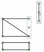
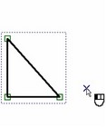
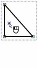
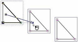
Next, two ways of acting are possible:
● Click ![]() and release without moving the pointer. Then move the pointer to the target point of copying and once again click
and release without moving the pointer. Then move the pointer to the target point of copying and once again click ![]() or press the <Enter> key. This way is convenient when moving objects from one page to another.
or press the <Enter> key. This way is convenient when moving objects from one page to another.
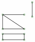
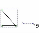
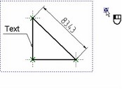
● Depress ![]() and move the pointer while holding down the mouse button. Moving will be completed when the button is released or the <Enter> key is pressed.
and move the pointer while holding down the mouse button. Moving will be completed when the button is released or the <Enter> key is pressed.
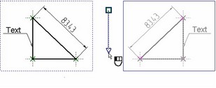
In either case, after first pressing of the ![]() both of the automenu and the property window will appear as appropriate in the "TM: Move" command. If necessary, you can switch to another moving, copying or array creation command, using the automenu or the property window.
both of the automenu and the property window will appear as appropriate in the "TM: Move" command. If necessary, you can switch to another moving, copying or array creation command, using the automenu or the property window.
Editing copy or array
All elements obtained by moving or non-associative copying can be edited as normal construction or graphic elements.
The associative copies created using the copying commands are edited by the command "EY: Edit Copy Operations". The command can be called by one of the following means:
Keyboard |
Textual Menu |
Icon |
<EY> |
"Edit|Draw|Copy" |
|
Upon calling the command, select the copies to be edited. To select one copy, you can use ![]() . Multiple selection can be done by box selection or selection by <Shift>+
. Multiple selection can be done by box selection or selection by <Shift>+![]() , <Ctrl>+
, <Ctrl>+![]() or by the automenu option:
or by the automenu option:
![]() <*> Select All Elements
<*> Select All Elements
When the copies are selected, both the selected and the original elements are highlighted, as well is the transformation vector (or the attachment point in the cases of scaling, rotating or creating a circular array).
Upon multiple selection of copies or arrays, the option is available in the automenu:
![]() <Del> Delete selected Element(s)
<Del> Delete selected Element(s)
Selection of a single copy or array makes the following options available in the automenu:
|
<Enter> |
Finish Editing |
|
<P> |
Set selected Element(s) Parameters |
|
<O> |
Explode Copy |
|
<G> |
Explode Copy keeping relations |
|
<H> |
Select Clipping Hatch (available only for translated, rotated and scaled copies) |
|
<K> |
Cancel selection of clipping Hatch (available only for copies clipped by a hatch) |
|
<S> |
Edit copied elements list |
|
<I> |
Select Other Element |
|
<Del> |
Delete selected Element(s) |
When selecting a copy (an array), the property window displays the dialog for editing the copy parameters, similar to that used at the time of the copy creation. It allows modifying the copy parameters. You can use the parameters dialog box for this purpose as well, called using the option ![]() .
.
The two options - ![]() and
and ![]() - are provided for breaking up copies, that is, for converting those into a set of independent elements. The copy (array) itself as a T-FLEX CAD element is deleted at this moment. The result of applying these options corresponds with the respective modes of the copy (array) creation. To delete a copy altogether, you can use the option
- are provided for breaking up copies, that is, for converting those into a set of independent elements. The copy (array) itself as a T-FLEX CAD element is deleted at this moment. The result of applying these options corresponds with the respective modes of the copy (array) creation. To delete a copy altogether, you can use the option ![]() .
.
The option ![]() is provided for editing the list of the original elements of the copy (array). In this mode, you can add the new elements to the list of the objects to be copied and delete some of the elements from the list of selected.
is provided for editing the list of the original elements of the copy (array). In this mode, you can add the new elements to the list of the objects to be copied and delete some of the elements from the list of selected.
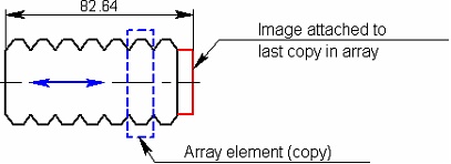
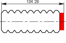
The option ![]() is accessible for copies created by the commands "XM: Create Copy", "XT: Copy and Rotate", "XA: Copy and Scale", “XE: Copy with Translation and Rotation”. It allows clipping the image of the copy by a hatch. To do this, upon calling the option, select the desired hatch by clicking
is accessible for copies created by the commands "XM: Create Copy", "XT: Copy and Rotate", "XA: Copy and Scale", “XE: Copy with Translation and Rotation”. It allows clipping the image of the copy by a hatch. To do this, upon calling the option, select the desired hatch by clicking ![]() .
.
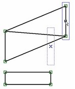
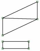
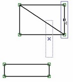
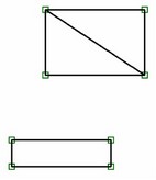
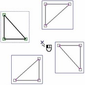
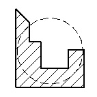
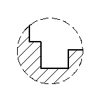
If the clipping hatch is used for this purpose only, we recommend setting its flag "Invisible". The diagram shows a copy image before and after selecting an invisible hatch for clipping. In addition to the described capabilities, the attachment points can be redefined for the selected copy (array).
To do this, select one of the transformation vector ends or an attachment point by clicking ![]() it (in the cases of scaling, rotating and the circular array). After that, specify the new attachment point(s). At this moment, the following options will be available in the automenu:
it (in the cases of scaling, rotating and the circular array). After that, specify the new attachment point(s). At this moment, the following options will be available in the automenu:
![]() <T> Create Node at point
<T> Create Node at point
![]() <N> Select Node
<N> Select Node
After defining the new attachment point, the element being edited will be drawn according to the applied changes.
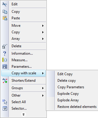
The commands for editing a copy or an array, or their elements, are also accessible via the context menu. Simply select one of the elements of a copy/array and right click You can change the properties of the selected element of a copy/array (the default properties are copied from the parent element). You can also delete the selected element of a copy/array (without deleting the copy itself). In this case, the copy/array itself maintains the information about the deleted element, so that it can be restored in the future. In the context menu of graphic lines obtained by copying, the “Shorten/extend” command is also available. This command allows us to modify the length of the visible part of the line. This function is described in more detail below. |
|
The editing commands for the copy/array itself are grouped in the context menu into a submenu, named according to the copy type (such as, "Move Copy", as shown on the diagram). An additional command is provided among the copy/array editing commands, "Restore deleted elements", specifically for restoring all deleted elements of the copy.
Changing length of visible part of a line obtained by copying
The “Shorten/extend” command, which is available in the context menu of graphic lines obtained by copying, allows us to modify the length of the visible part of the line. It is possible both to shorten and extend the line of the copy. However, the function of extension is only available for segments and arcs.
The part of the line that is to be changed is indicated by 2D nodes. At first when you work with the command it is required to indicate the part of the line which must be modified, then – the node which defines the new end point of the line. For closed lines it is necessary to indicate two nodes and the part of the line which must remain. The 2D nodes, which are being used, can be located on the line itself or at some distance away from it. In the latter case the end point of the line is defined as a point on the line that is the closest to the selected node.
The context menu for the line modified with the help of the “Shorten/extend” command contains the “Reset” command. It allows us to quickly restore the original appearance of the line-copy.
Removing original objects of copy/array
When deleting an original element of the copy/array, two variants of the system's response are possible depending on the option selected in the dialog of the command of deletion.
If the “Delete selected and dependent elements” option is chosen, the element that is being removed is simply excluded from the set of original elements of the copy/array. As a result, the view of the copy/array will change: the elements obtained by copying of the element that has been deleted will disappear.

When the “Delete only selected elements by changing the way of specifying the dependent elements” option is selected, the element that is being removed is also excluded from the original set of the copy/array. But, in addition, instead of copies that have been disappeared, identical externally free objects are created. This means that the result of copying visually does not change.
Copying between pages with different scales
The dialog of parameters of the already created 2D copy (by translation, rotation, scaling – except symmetry) contains two additional flags: “Correction for a scale of model” and “Compensate scales of pages”. These flags are taken into account when copying between pages is performed. The “Correction for a scale of model” flag is available only for translations created automatically upon construction of taken out elements. |
|
Description of this flag can be found in the “Drawing views. Taken out elements” chapter.
The “Compensate scales of pages” flag allows us to achieve the correct ratio between the dimensions of the elements on the original page and the resulting page of copying when the scales of these pages are different. When this flag is enabled, to obtain the scale of the copy, the scales of both pages are taken into consideration:
Resulting scale of the copy |
= |
Given scale of the copy* Scale of target page of copying |
Scale of original page of copying |
By default, this flag is enabled.
Particulars of handling variable arrays
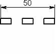
When modifying the number of copies in a linear or circular array, adding or deleting copies occurs in the position immediately before the last copy in the array. This feature helps, for instance, keeping the dimensions between the outer elements of the array throughout modifications to the number of copies in the array. The dimensions set on "inner" copies of the array may disappear as the total number of copies is reduced. The same is true for any 2D constructions: the elements attached to the outer copies of an array will always maintain the correct position, regardless of the changes to the array.
When creating a hatch based on an array elements, hold on to the following technique: before creating the hatch, set the maximum necessary number of copies in the array. The hatch should be defined using the automatic contour search mode. In this case, the hatch will behave correctly in the future and will not "break" under any modifications to the number of copies in the array (within the initially defined range).
In the three-dimensional modeling mode, a 2D array placed on a workplane can be used for creating a 3D profile. The profile can be created based either on the graphic lines directly, or on the hatch constructed by those graphic lines. When using an array with a variable number of elements, use of an intermediate hatch (based on the lines of the array) for the profile creation makes sense only in the case when you know the maximum number of copies in the array. In all other cases, the 3D profile should be created based on the graphic lines of the array. In the course of future construction, keep in mind that indexing of geometrical items within the resulting 3D element (such as edges, vertices, etc.) will be changing, as you modify the number of copies in the array that defines this 3D element.
Copying via clipboard
Besides the moving, copying and array creation commands, T-FLEX CAD also supports the mechanism of copying via the clipboard. Its function is mostly similar to the copying command "XM: Create Copy", yet has some additional capabilities. The clipboard allows copying any 2D elements, except for the drawing views and multipage text and BOMs. This mechanism is recommended for use in the following cases:
● For copying across several documents within the same T-FLEX CAD application;
● For exchanging data with other applications.
Copying via the clipboard includes four commands available in the context menu and in the menu "Edit" after selecting the objects to copy: "XC: Copy", "XI: Copy with Insertion Point", "XP: Paste", “XE: Paste Special”.
The standard key combinations are used with the clipboard: <Ctrl><C>, <Ctrl><V>, <Ctrl><Ins>, <Shift><Ins>.
The command "XC: Copy" - places the selected object on the clipboard:
Icon |
Ribbon |
|---|---|
|
Edit → Edit → Copy |
Keyboard |
Textual Menu |
<XC>, <Ctrl><C> |
Edit > Copy |
To use this command, simply select the elements, and then call the command. No additional actions are required. When later pasting the copied objects into the T-FLEX CAD document, you can use the characteristic points of the copied object (center, upper left corner, upper right corner, etc.).
The command "XI: Copy with Insertion Point" - places the selected object on the clipboard with the specified attachment point:
Icon |
Ribbon |
|---|---|
|
Edit → Edit → Copy with Point |
Keyboard |
Textual Menu |
<XI> |
Edit > Copy with Point |
Upon calling the command and selecting objects, you need to specify an arbitrary point (2D node), to which the objects will be attached when pasted in the T-FLEX CAD document. The following options will be available in the automenu in this case:
![]() <N> Select Node
<N> Select Node
![]() <A> Set absolute coordinates
<A> Set absolute coordinates
![]() <Esc> Cancel selection
<Esc> Cancel selection
Object snapping is active when defining the point, similar to that used in sketching. Upon pasting the copied objects in the T-FLEX CAD document, the attachment can be defined by specifying a point or by the characteristic points of the copied object.
When copying, the data are put on the T-FLEX CAD clipboard in a specific internal format. Besides that, to ensure interaction with external applications, the selected drawing elements are placed on the clipboard in the image format Enhanced Metafile (EMF). However, if a single element of the type "Text" was selected for copying, then additionally the textual data is placed on the clipboard in the following formats:
1. T-FLEX Paragraph Text (except the string text),
2. RTF (except the string text),
3. Unformatted text.
This supports data exchange both within the same T-FLEX CAD application and across several different applications.
To insert data from the clipboard, use the commands “XP: Paste”, “XE: Paste Special”.
These commands are available only if there is some data in the clipboard.
The command “XP: Paste”:
Icon |
Ribbon |
|---|---|
|
Edit → Edit → Paste |
Keyboard |
Textual Menu |
<XP>, <Ctrl><V> |
Edit > Paste |
In this command, the format selection upon pasting the clipboard contents is done by the application itself.
The program scans through the clipboard, searching for the appropriate format among the clipboard data. The data will be pasted in the first appropriate format found. The order of the format search is as follows:
1. Internal T-FLEX CAD format (used only when copying within one T-FLEX CAD application)
2. T-FLEX Paragraph Text
3. RTF
4. Unformatted text
5. EMF
6. BMP (bitmap image)
Upon calling the command, the elements being pasted will be rubberbanding with the pointer. The attachment point for the elements being pasted is defined by clicking ![]() or by using the option
or by using the option ![]() .
.
The following options are provided in the automenu:
![]() <N> Select Node
<N> Select Node
![]() <E> Use Variables when names are coincident (only when pasting in another T-FLEX CAD document)
<E> Use Variables when names are coincident (only when pasting in another T-FLEX CAD document)
![]() <Alt><T> Copy only selected elements
<Alt><T> Copy only selected elements
![]() <U> Move along X axis (only when pasting in the same T-FLEX CAD document)
<U> Move along X axis (only when pasting in the same T-FLEX CAD document)
![]() <V> Move along Y axis (only when pasting in the same T-FLEX CAD document)
<V> Move along Y axis (only when pasting in the same T-FLEX CAD document)
![]() (Selection of the attachment point)
(Selection of the attachment point)
![]() (Selection of the action after pasting)
(Selection of the action after pasting)
![]() <Esc> Exit command
<Esc> Exit command
The options ![]() and
and ![]() are used for blocking pointer movement in the directions of the respective coordinate axes. To specify the exact position of the copied elements or the offset with respect to the original object, use the command property window. This option is available only when pasting the copied elements in the same T-FLEX CAD document.
are used for blocking pointer movement in the directions of the respective coordinate axes. To specify the exact position of the copied elements or the offset with respect to the original object, use the command property window. This option is available only when pasting the copied elements in the same T-FLEX CAD document.
The group of options for selecting the attachment point allows specifying the point to which the pasted object should be attached. The characteristic points of the object are available for selection. If the objects were placed on the clipboard by using the command "XI: Copy with Insertion Point", then an additional attachment point can be defined in the command being discussed (the option ![]() ).
).
When using the clipboard copying mechanism, the system forces copying of the parent elements of the objects being copied (in the cases, when the former were not explicitly included in the set of the copied elements). This feature is similar to that used in the copying mode "Explode Copy keeping relations". In the current case, you can also prohibit this system behavior by using the option ![]() . With this option activated, the elements, whose parents were not included in the set of elements to be copied, will be converted into independent objects.
. With this option activated, the elements, whose parents were not included in the set of elements to be copied, will be converted into independent objects.
The copied elements can have relations with variables (except for the variables describing the position of these elements). To replace the respective parameters of the elements being copied by the variables defined in the target T-FLEX CAD document (the document where the elements are copied to), use the option ![]() . This option is only available when pasting the copied elements in another T-FLEX CAD document within the same active application. If the option
. This option is only available when pasting the copied elements in another T-FLEX CAD document within the same active application. If the option ![]() is turned on, the names of the variables are compared in the target document versus those in the copied objects. If the names coincide, then the copied elements take on the relations with the respective variables of the current document. The variables, for which no match is found, are replaced by their values. If this option is turned off, the relations with all variables are broken, the variables being replaced by constants.
is turned on, the names of the variables are compared in the target document versus those in the copied objects. If the names coincide, then the copied elements take on the relations with the respective variables of the current document. The variables, for which no match is found, are replaced by their values. If this option is turned off, the relations with all variables are broken, the variables being replaced by constants.
The group of options ![]() is used for the same purpose as in the moving, copying and array creation commands. Those define the action that will be automatically performed upon completion of pasting the clipboard contents. The following choices are provided:
is used for the same purpose as in the moving, copying and array creation commands. Those define the action that will be automatically performed upon completion of pasting the clipboard contents. The following choices are provided:
![]() - the system exits the command after pasting the clipboard contents;
- the system exits the command after pasting the clipboard contents;
![]() - repeated pasting mode - upon pasting the first instance, the copied object starts rubberbanding with the pointer. The system waits for the user inputting the attachment point for the next copy. Upon selecting a second point, another copy is pasted, and so on. The copy creation can be interrupted by right clicking
- repeated pasting mode - upon pasting the first instance, the copied object starts rubberbanding with the pointer. The system waits for the user inputting the attachment point for the next copy. Upon selecting a second point, another copy is pasted, and so on. The copy creation can be interrupted by right clicking ![]() or pressing
or pressing ![]() ;
;
![]() - the copying command "XI: Copy with Insertion Point" is automatically executed over the pasted object;
- the copying command "XI: Copy with Insertion Point" is automatically executed over the pasted object;
![]() - is similar to the previous choice; however, before calling the copying command, the system turns on the mode of editing the list of selected elements.
- is similar to the previous choice; however, before calling the copying command, the system turns on the mode of editing the list of selected elements.
When pasting data from different applications, either a textual or a graphic format is used. If a textual format is used, then a "Paragraph text" element is automatically created, and then its editing command is launched, "ET: Edit Text". When inserting images, the command is launched for the "Picture" element creation, "IP: Insert Picture".
The dialog box will appear when pasting clipboard data with AutoCAD objects into a T-FLEX CAD document (see more details in "Exporting and Importing Documents" chapter). This dialog is used for specifying the general import parameters of an AutoCAD document. Then "XP: Paste" command will start for setting location parameters of the elements being inserted - position, angle of rotation, scale factor.
The command “XE: Paste Special”:
Icon |
Ribbon |
|---|---|
|
Edit → Edit → Paste Special… |
Keyboard |
Textual Menu |
<XE> |
Edit > Paste Special… |
This command allows the user to manually select a format for the clipboard contents to be pasted. The command dialog displays the list of formats present in the clipboard at the time of calling the command. Depending on what format the user selects, the system goes into the T-FLEX CAD object pasting mode, or pasting pictures in the EMF or BMP format, plain text or formatted text (RTF).