Drawing Modification via Dimensions |
  
|
Drawing Modification via Dimensions |
|
T-FLEX CAD has the capability of modifying the model (3D model or 2D drawing) by using the dimensions. The user specifies the new dimension nominal value, and the system automatically rebuilds the 3D model or drawing based on parametric dependencies. Such editing is supported for both 2D dimensions (that is, dimensions in a drawing) and for 3D dimensions (dimensions in a 3D model), as well as their corresponding dimensions on 2D projections.
Decides that, there is a provision for automatically calculation of all dimensions to the middle of the tolerance range.
Dimension value modification command
In T-FLEX CAD it is possible to edit both the drawing and the 3D model by modifying the nominal values of dimensions created therein.
The command "PE: Set Dimension Values" is used for this purpose. The command can be used either in the "transparent mode" or explicitly called by one of the following means:
Icon |
Ribbon |
|---|---|
|
Parameters → Tools → Set Value |
Keyboard |
Textual Menu |
<PE> |
Parameters > Dimensions > Set Value |
Besides that, this command is available in the context menu when selecting a dimension (whether a 2D dimension or a 3D dimension).
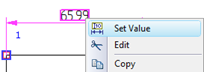
To enable the command in the transparent mode, you need to set the flag Dimension edit is transparent in the command "SO: Set System Options", the tab 2D. After that, selecting any dimension value string by ![]() launches the command "PE: Set Dimension Values". The selected dimension value is highlighted, ready for editing.
launches the command "PE: Set Dimension Values". The selected dimension value is highlighted, ready for editing.
If the "transparent mode" is not set for this command, dimension values can be selected for editing only after the explicit command call.
When a dimension value is modified, the system tries to find one construction element, whose modification affects the dimension value. If such element is found, it will be modified according to the requested dimension value. Otherwise, the drawing will stay unchanged. If several such construction elements are found, then the system will select the one of them, whose modification will affect as few other dimensions as possible. When the position of a construction line element is modified, other 2D elements will be adjusted as well (including construction lines and/or graphic lines, dimensions, leader notes, etc.), that are related with it. If the position of the elements being adjusted was driven by variables, then the system will query you for the automatic adjustment of their values.
Upon calling the command, the following icons appear in the automenu:
![]() <Enter> Finish Value input
<Enter> Finish Value input
![]() <Esc> Exit command
<Esc> Exit command
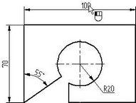
Select the dimension and enter the new nominal value:
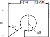
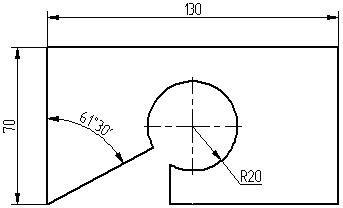
Then confirm the input by pressing the <Enter> key or ![]() . As was already mentioned, the drawing changes only when it is possible.
. As was already mentioned, the drawing changes only when it is possible.
The command will not work correctly in the following cases:
● The flag "Manually" is set in the dimension parameters, or the parameter "Dimension text" is assigned the value "No parameters".
● The referenced construction elements definition does not allow their position modifications. For example, you cannot change the value of a circle radius if the circle is tangent to three entities.
● Changes in the construction entity positions caused by the dimension modification make the system unable to define the position of some element with respect to other affected entities.
In all of these cases, the dimension reverts to the original value, with no changes done to the drawing.