Routing Styles |
  
|
Routing Styles |
|
Style is a group of settings designed for automatic filling of routes with the routing objects. Styles usually correspond to standards that are commonly used in the routing design. For example, parts of the pipeline must often comply with certain requirements in length and diameter; in addition, these parts should include fittings of certain materials.
Style definitions are managed in the editor of Styles. With the editor, you can view, add, edit, and delete styles. The definitions of styles can be also imported and exported using file in .xml format. You can change any of the default styles, or use them as the basis for creating new custom styles. In addition, custom styles can be created based on the empty style.
Editor of styles can be called from the Routing menu:
Icon |
Ribbon |
|---|---|
|
Routing → Options → Styles |
Keyboard |
Textual Menu |
|
Tools > Routing > Styles |
After calling the command you will see the dialog of Routing Styles editor.
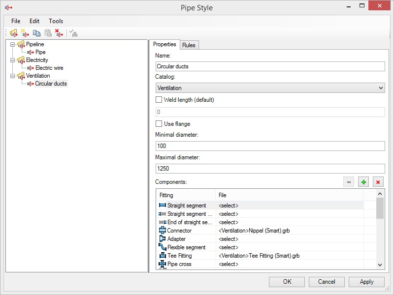
There is a toolbar in the upper part of the dialog:
![]() Create Catalog creates new folder-catalog for styles.
Create Catalog creates new folder-catalog for styles.
![]() Create Style creates new style in the current catalog.
Create Style creates new style in the current catalog.
![]() Copy Style copies selected style.
Copy Style copies selected style.
![]() Paste Style paste copied style into selected catalog.
Paste Style paste copied style into selected catalog.
![]() Delete deletes style or catalog.
Delete deletes style or catalog.
![]() Update information about fittings – updates information about routing objects (fittings).
Update information about fittings – updates information about routing objects (fittings).
On the left there is a list of catalogs and styles availabe for usage.
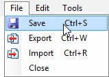
Created styles can be exported and imported in *.xml format with the appropriate commands in the File menu.
Parameters of the selected style are displayed in the right pane.
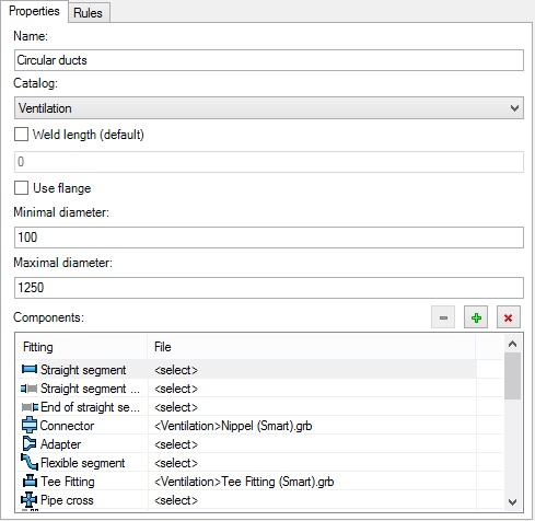
Properties tab Name. In this field you can set the name of style that will appear in the list in the left pane. Catalog. The drop-down list contains catalogs that may include the selected style. You can create a new catalog by selecting the appropriate menu item from the drop-down list, if desired. Weld length (default). When the flag is active, you can set the default weld length. Use flange. Defines the usage of flanges for style. Minimal and Maximal diameters define the permissible routing diameters. Components window displays the list of fitting types and their corresponding files.
|
|
You may use the following button when working with the Components dialog:
![]() Delete Component. Deletes selected file from the list.
Delete Component. Deletes selected file from the list.
![]() Select Component. Adds file to the list.
Select Component. Adds file to the list.
![]() Delete All Components. Deletes all files from the list.
Delete All Components. Deletes all files from the list.
After mouse click in the <Select> field or pressing button![]() , the following window appears:
, the following window appears:
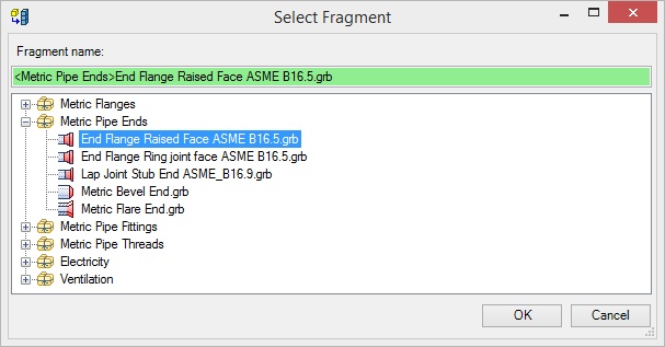
This window displays all library files available for selection.
If the fragment name is highlighted in red, it cannot be selected.
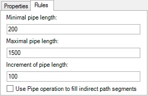
Rules tab. Minimal pipe length, Maximal pipe length - set the minimal and maximal length of the pipeline segment. Increment of pipe length. You can specify the length of increment. Increment of length is a step with which the system takes into account the above conditions. Use Pipe operation to fill indirect path segments. When the flag is set the pipeline will be bent with a given style. |
|
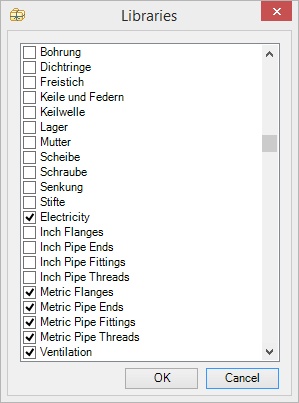
List of libraries for selection consists of libraries marked as available for selection. Use Tools >> Libraries command of Routing Styles dialog menu to mark necessary libraries in the list of all system libraries.
Filling Route with Style
To apply styles, use command route Fill route with style, available for all types of routings.
Icon |
Ribbon |
|---|---|
|
Routing → Construct → Fill route with style |
Keyboard |
Textual Menu |
|
Tools > Routing > Pipeline > Fill route with style |
The following actions are available in automenu after activating the command:
|
<P> |
Select Route |
|
<B> |
Select start point on route |
|
<E> |
Select end point on route |
|
<D> |
Cancel start and end points |
|
<A> |
Select alternative routes |
|
<L> |
Cancel alternative routes |
|
<N> |
Next |
|
<M> |
Back |
|
<C> |
Clear Route |
|
<R> |
Resume command operation after applying changes |
![]() Upon activation, you need to select the main route to create routing.
Upon activation, you need to select the main route to create routing.
![]() and
and ![]() allow to set limit for routing. Element will be generated or deleted on the specified segment of the route.
allow to set limit for routing. Element will be generated or deleted on the specified segment of the route.
![]() Cancels selection of the start and end points.
Cancels selection of the start and end points.
![]() Allows you to choose alternative the routes. These routes must be connected with the main route.
Allows you to choose alternative the routes. These routes must be connected with the main route.
![]() Cancels selection of all alternative routes.
Cancels selection of all alternative routes.
![]() Provides preview of the operation result. After the first press preview is done on the main route
Provides preview of the operation result. After the first press preview is done on the main route ![]() , after the next pressing – on alternative
, after the next pressing – on alternative ![]() .
.
![]() Returns to the previous preview step.
Returns to the previous preview step.
![]() Deletes all routing components of a route - nodes, LCS, fragments.
Deletes all routing components of a route - nodes, LCS, fragments.
![]() Allows you to create a new routing immediately after the creation of the current routing.
Allows you to create a new routing immediately after the creation of the current routing.
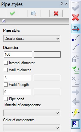
In the Properties window, you can specify parameters for the created element. Pipe Style - one of the styles for filling routes can be selected from the drop-down list. The list stores up to ten previously used styles. Diameter – pipeline diameter is set here. Diameter should be in the range specified in the parameters of the selected style. Internal Diameter - when checked, the defined diameter is treated as internal. Wall Thickness - allows you to specify thickness of the pipe wall. Weld / length – this field defines the gap between the components for welding. Pipe bend. If library does not have appropriate fitting for rounding, then this option will bend the pipe. When you bend pipe weld option is not taken into account. Material of components. This list contains materials used in the current model. Color of components. Color of shading for pipeline elements. Green and red colors in the data fields show the possibility of correct usage of the entered value. |
|
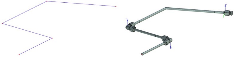
Original route |
Route filled with style |