Creating Macros with Screen Forms |
  
|
Creating Macros with Screen Forms |
|
In certain situations, the user needs to be able to input certain element parameters in the dialog while running a macro. To realize this capability, the macro editor supports creation of screen forms that can contain controls. Follows below is the overview of the macro editor tools supporting creation of macros with screen forms.
«Toolbox» window
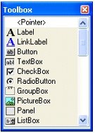 The «Toolbox» window can be accessed from the macro editor textual menu as: View|Tools. The «Toolbox» window contains a set of control elements that can be placed on a form. The elements appear in this window only when the form is active. Otherwise, the window will be empty.
«Properties» window
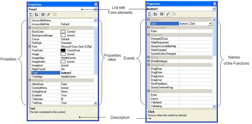
The window can be called via the textual menu of the macro editor: «View|Properties». It serves for viewing and specifying properties and events (methods) of a form and elements placed on the form. This window remains empty until a form or an element located on the form is selected.
Control element properties are the parameters defining an object's characteristics (name, color, position etc.).
Events of control element are the actions performed over the object of a control element, such as clicking a «Button» control element. While a program (macro) is running, a control element event gets bound to executing certain commands. For example, the event of clicking a «Button» control element can be bound to creating a T-FLEX CAD object.
The upper part of the «Properties» window contains the list with form elements. To view and modify properties of a form element, select it in the list or select the element on the screen form itself by ![]() .
.
The «Properties» window works in one of the two modes:
● If the «Properties» option ![]() is active on the window toolbar, then the window will be displaying element properties.
is active on the window toolbar, then the window will be displaying element properties.
● If the «Events» option ![]() is active, then the window displays events.
is active, then the window displays events.
The «Properties» window is divided into two parts. The left column displays the names of the object properties. The right column displays property values.
If the window is in the mode of showing events, then the right hand side column of the window displays the events attainable for the given element type. The left-hand side column shows the names of the functions that are currently used for the given element and event.
The buttons ![]() and
and ![]() allow sorting the list of object properties alphabetically and by categories, respectively.
allow sorting the list of object properties alphabetically and by categories, respectively.
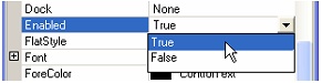 For some properties, you can specify only strictly defined values. In such a case, the value input field will be represented by a combo box; when accessed, this combo box displays the property values available for selection.
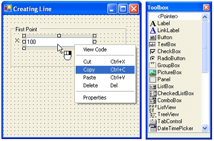
Placing control elements on form
To place control elements on a form, you need to complete the following steps:
●Select the form to which you need to add a control.
●Select the desired element in the «Toolbox» window.
●Click ![]() anywhere on the form. Upon that, the selected control element will be added to the form.
anywhere on the form. Upon that, the selected control element will be added to the form.
●Drug the control to the desired position on the form.
Writing procedures for control elements on forms
After placing control elements on forms, you need to bind those elements to the executable code. The code responsible for processing events of the given control element is contained in a dedicated «Code» window corresponding to the given form. There are two ways to access this window:
●In the «Projects» window, call the command «Open Code» from the context menu of the selected form. Doing so opens the window containing executable code for the form, so that you can add procedures for processing control element events in this form.
●Double-click ![]()
![]() the control element on the form or call this command from the context menu of the control element. This brings up a window and automatically creates a procedure there for processing the driving method of the respective element. Default events are defined for each control element.
the control element on the form or call this command from the context menu of the control element. This brings up a window and automatically creates a procedure there for processing the driving method of the respective element. Default events are defined for each control element.
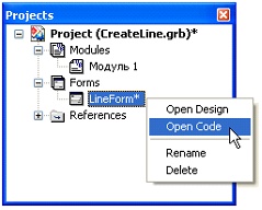
You can switch between the form window and the code window either by the context menu commands of this form («Open Design», «Open Code»), or with the help of the respective tabs located under the code window.
Code window for control elements on form
The code window is a text editor that allows writing procedures for processing control element events for the given form.
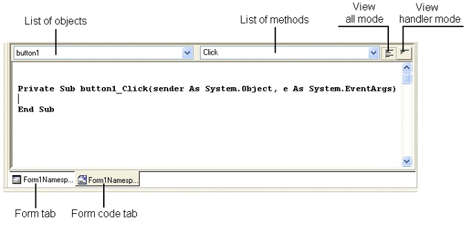
At the top of the window there are two lists: the first one displaying all objects on the form, while the second one - the methods related to the selected object from the first list. Methods are the actions or tasks performed by the given object (the control element on the form).
The code window provides control over the number of displayed procedures. For this purpose, two buttons are provided in the upper right corner of the window:
![]() – View all mode;
– View all mode;
![]() – View handler mode.
– View handler mode.
To add a new procedure, select an element in the list of objects, and then select the desired method for that element in the list of methods. By doing so, an appropriate procedure will be added in the code window.
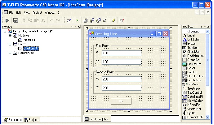
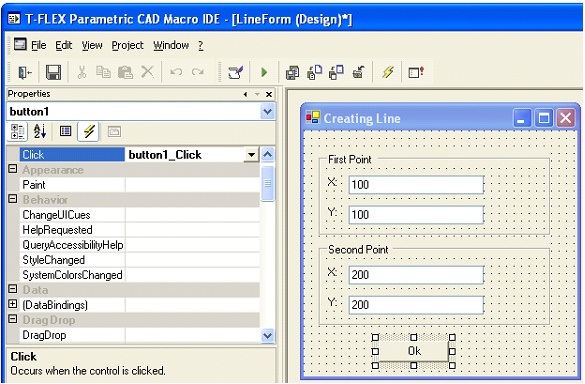
Example of macro with screen form
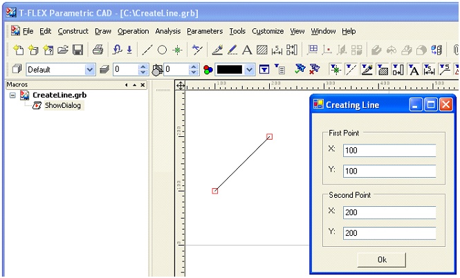
Let's review an example of a macro written in the Visual Basic programming language. Executing the macro creates a segment between two 2D nodes. Coordinates of those nodes are entered via a dialog.
Initially, a form «FormLine» was created in the Project «CreateLine.grb», and then controls were placed on it, which will be used for defining 2D nodes coordinates. Another control element was added to the form – a button, clicking which would launch the function creating the 2D nodes and the segment between them.
Upon placing control elements on the form, one needs to define processing of the event of clicking the control element – the button. To do this, select that element on the form, switch to the «Properties» window and set the latter window into the event mode ![]() .
.
In the right hand side column of the «Click» event, press ![]() , which will create the procedure «button1_Click». The same result could be achieved by double-clicking
, which will create the procedure «button1_Click». The same result could be achieved by double-clicking ![]()
![]() the control element – the button.
the control element – the button.
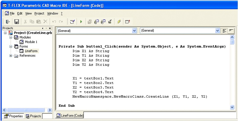
In the coming up form code window, one needs to write the procedure «button1_Click».
The figure below depicts the form code window containing the function «button1_Click», in which the variables «X1», «Y1», «X2» and «Y2» are assigned values from control elements – the textBox1, textBox2, textBox3 and textBox4 input boxes, and «CreateLine» function (macro) is called.
After that, let's create a module, in which two functions are to be written. The function «ShowDialog» (a standard function of the development environment) will be displaying the screen form upon launching the macro. The previously defined function «CreateLine» creates 2D nodes, whose coordinates are the values specified by the user via the «FormLine» form dialog, and the segment between those nodes. The module's source code is shown below.
'Declaring references
Imports System
Imports TFlex
Imports TFlex.Model
Imports TFlex.Model.Model2D
'Declaring namespace
Namespace NewMacroNamespace
'Declaring class
Public Class NewMacroClass
'The function, which will display the screen form «form» when executed
Public Shared Sub ShowDialog()
Dim form As LineForm
form = new LineForm()
form.ShowDialog()
End Sub
'The function with parameters (the macro), which creates a graphic line between two 2D nodes.
'Coordinates of those nodes are input in the function as the dialog parameters
Public Shared Sub CreateLine(ByVal NodeX1 As String, ByVal NodeY1 As String,
ByVal NodeX2 As String, ByVal NodeY2 As String)
Dim document As Document
document = TFlex.Application.ActiveDocument
'Opening block of documents changes
document.BeginChanges("Creating graphic lines")
'Creating graphic line and 2D free node objects
Dim line As ConstructionOutline
Dim node1 As FreeNode
Dim node2 As FreeNode
Dim X_1, Y_1, X_2, Y_2 As Double
X_1 = System.Convert.ToDouble(NodeX1)
Y_1 = System.Convert.ToDouble(NodeY1)
X_2 = System.Convert.ToDouble(NodeX2)
Y_2 = System.Convert.ToDouble(NodeY2)
'Creating 2D free nodes
node1 = new FreeNode(document,new Parameter(X_1),new Parameter(Y_1 ))
node2 = new FreeNode(document,new Parameter(X_2),new Parameter(Y_2 ))
'Creating graphic line between two nodes
line = new ConstructionOutline(document,node1,node2)
'Closing block of document changes
document.EndChanges()
End Sub
End Class
End Namespace
When the macro is executed in T-FLEX CAD, the «FormLine» dialog appears. Upon clicking the control element – the «OK» button, a segment will be created between the two nodes in the drawing area.